Abstract
Combustion is ubiquitous around us and in the technology that we depend on in our daily lives. To someone uninitiated in the field, observing the combustion process can produce emotions ranging from apathy, fear, boredom, conservatism, or caution to outright joy, including love and affection. Observing combustion is also a great source of fascination to many, in particular to scientists and engineers, who seek to understand the intricate relationships among the chemical, thermal, fluid dynamic, and other complex phenomena involved in the combustion process. The wide variety of fuel and oxidizers, operating conditions such as initial temperature, pressure, and concentrations, and combustor geometry configurations create virtually limitless combinations of combustion, observed visually as flame(s). For example, flames of gaseous, liquid, and solid fuels share many similarities, but they also exhibit their own unique features. Flames do not depict all of their features naturally, and thus researchers employ various diagnostics techniques, often laser-based, to measure one or more characteristics, which can also unravel the mysteries of soot, nitric oxide, and carbon oxide formation, and/or help address various safety-related issues such as flame flashback, flame blow-off, flame noise, etc. The ultimate goal of such explorations is to develop clean combustion systems that are fuel agnostic, highly efficient, and, most importantly, environmentally friendly, i.e., they produce low or very low levels of harmful emissions, including greenhouse gas emissions. This chapter presents simple canonical flames, free from the complexities of most practical combustion systems, to offer insight into the key phenomena. This chapter is divided into eight sections, each covering a different aspect of laboratory-scale flames.
Introduction
Combustion is ubiquitous around us and in the technology that we depend on in our daily lives. To someone uninitiated in the field, observing the combustion process can produce emotions ranging from apathy, fear, boredom, conservatism, or caution to outright joy, including love and affection. Observing combustion is also a great source of fascination to many, in particular to scientists and engineers, who seek to understand the intricate relationships among the chemical, thermal, fluid dynamic, and other complex phenomena involved in the combustion process. The wide variety of fuel and oxidizers, operating conditions such as initial temperature, pressure, and concentrations, and combustor geometry configurations create virtually limitless combinations of combustion, observed visually as flame(s). For example, flames of gaseous, liquid, and solid fuels share many similarities, but they also exhibit their own unique features. Flames do not depict all of their features naturally, and thus researchers employ various diagnostics techniques, often laser-based, to measure one or more characteristics, which can also unravel the mysteries of soot, nitric oxide, and carbon oxide formation, and/or help address various safety-related issues such as flame flashback, flame blow-off, flame noise, etc. The ultimate goal of such explorations is to develop clean combustion systems that are fuel agnostic, highly efficient, and, most importantly, environmentally friendly, i.e., they produce low or very low levels of harmful emissions, including greenhouse gas emissions. This chapter presents simple canonical flames, free from the complexities of most practical combustion systems, to offer insight into the key phenomena. This chapter is divided into eight sections, each covering a different aspect of laboratory-scale flames.
The first section contains images of (1) laminar diffusion flames to illustrate how shape and sooting tendencies are affected by the oxidizer flow rate in a simple Burke–Schuman burner as shown in Figure 1.1; (2) a premixed methane–air flame exhibiting blue color distinct from the yellow color of diffusion flames as shown in Figure 1.2; and (3) a triple flame comprised of both diffusion and premixed flames in a single flame. The flames widen when gravity-induced buoyancy is removed, as shown in Figures 1.3 and 1.4. Figure 1.5 shows a well-defined conical reaction zone in a premixed flame, which can become corrugated by the presence of turbulence in the reactant flow. Images illustrate various phenomena captured by multiple observational techniques, including shadowgraph and color schlieren.
The images in Section 1.2 show one of the simplest flame configuration, the so-called one-dimensional flame obtained in a counterflow burner configuration. Images show how flame thickness, flame position, flame color, and/or flame luminosity are all affected by the oxidizer, equivalence ratio, hydrogen enrichment, strain rates, etc. Tulip flames obtained experimentally and computationally are shown in Figure 1.12. Transition in turbulent flames and flame propagation in narrow channels are illustrated next.
Figures 1.15 and 1.16 show vortical structures associated with noise generation in flames. The flame structure and its noise characteristics can be improved by introducing a porous structure within the combustor as shown in Figure 1.17.
Section 1.4 presents spherical flames created by locally igniting the reactant mixture. As the flame propagates radially, and the flame front increases in size, the cellular instabilities are formed and can be clearly observed.
Section 1.5 presents examples of liquid flames, produced either by injecting the fuel into the oxidizer or by allowing the fuel to find the oxidizer, such as in pool fires.
Section 1.6 presents an example of combustion at supersonic conditions.
Combustion of coal particles, one of the most prevalent solid fuel in use, is illustrated in Section 1.7. Coal can be burned alone or in combination with other gaseous fuels. Figures 1.26–1.28 show that metals can also burn when introduced in typical methane–air flames, and produces interesting features.
Section 1.8 shows that different metal powders and/or metals burning in air exhibit similarity to gaseous fuel combustion.

1.1 Different Types of Simple Flames
1.1.1 Overventilated and Underventilated Axisymmetric Laminar Diffusion Flames in a Burke–Schumann Burner
Overventilated (left) and underventilated (right) laminar diffusion flames are shown. Overventilated flames are closed on the axis of symmetry of the burner while underventilated flames are open and terminate over the external oxidant tube. The two types of flame can be obtained keeping the flow momentum of the reactants equal and by changing the fuel tube radius, a, the Peclet number, Pe, or the initial mass fraction of oxygen in air, YO0. Furthermore, they can be obtained by varying the mass flow rates of one of the reactants and keeping constant the flow rate of the other.
The left image shows an overventilated CH4/air flame, with a = 3 mm and fuel velocity of 550 mm/s obtained in the visible spectrum as well as with optical filters for C2 and CH radicals detection. The right image shows an underventilated CH4/air flame obtained by keeping constant the mass flow rate of CH4 while reducing the mass flow rate of air in the visible spectrum and with optical filters for C2 and CH radicals detection.
This research was partially funded by CAPES Brazilian Research Support Agency.
Reference
1.1.2 Crossed Slot Burner – Premixed Methane Air – Near Blow-off
This image is of a premixed methane air flame on a steady-state slot burner. The slots are in the shape of a cross on top of a circular cap. The equivalence ratio is near stoichiometric, and the flow rate is high enough that the edges of the flame lift off of the burner while the center core remains anchored.
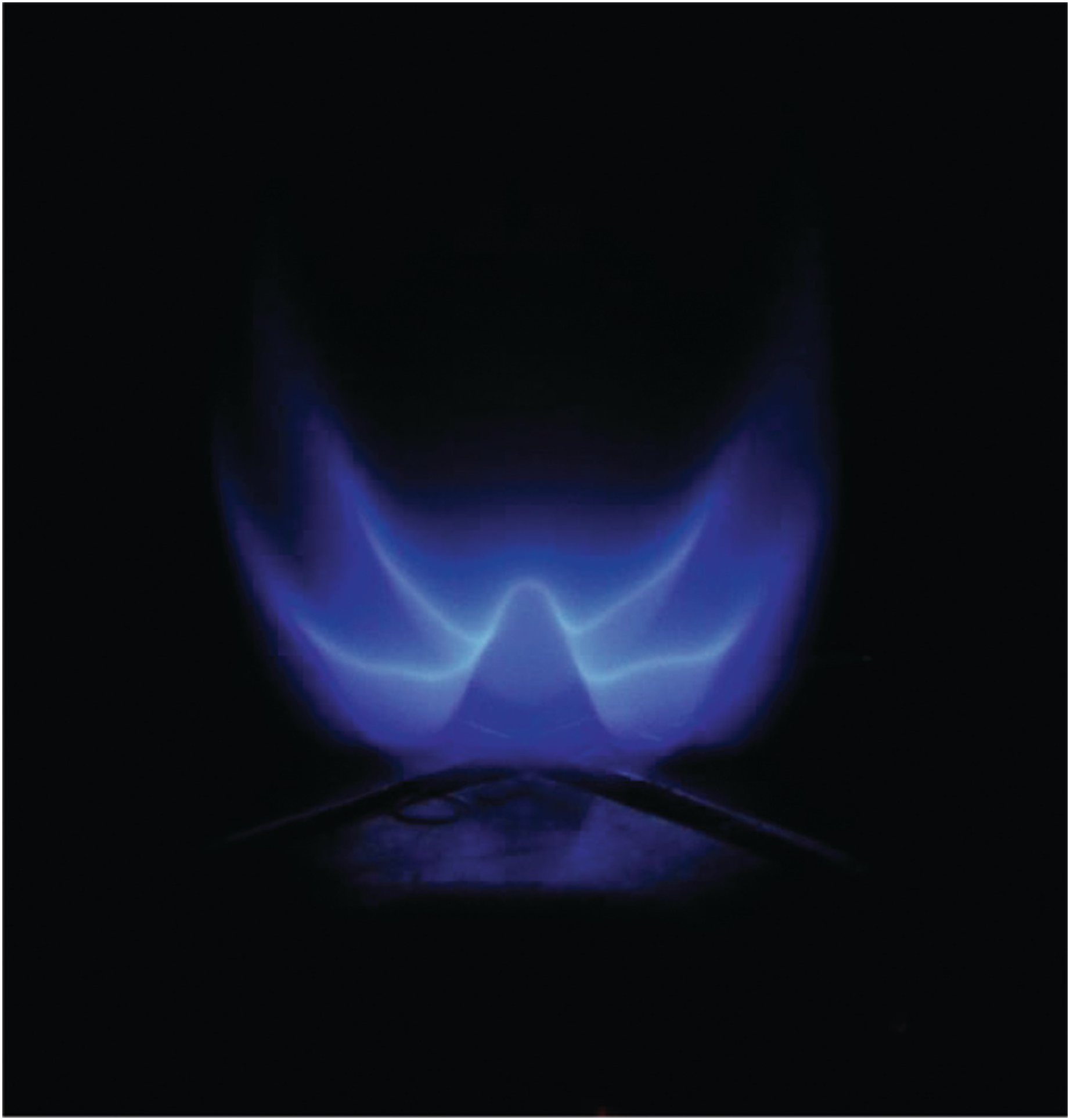
1.1.3 Laminar Triple Flames at Normal Gravity and Microgravity

The left-side contains direct images of methane triple flames under normal (1g) and microgravity (μg) established on a Wolfhard–Parker slot burner by introducing a fuel rich methane-air mixture from an inner slot and a fuel lean mixture from two symmetric outer slots. A triple flame is characterized by three reaction zones. Two premixed reaction zones (one fuel–rich on the inside and the other fuel–lean on the outside) form the exterior “wings”of the flame, and a nonpremixed reaction zone is established in between the two wings. While the inner rich premixed zone is only weakly affected by gravity, the outer lean premixed zone and the nonpremixed zone are noticeably influenced by buoyancy.
The right-side image compares the computed and measured triple flames in terms of the computed volumetric heat release rates and the experimentally measured C2*-chemiluminescence intensities. While all three reaction zones are clearly visible in the computed heat release rate contours, the lean premixed reaction zone is not quite as evident in the experimental image, since the fuel lean chemistry is not captured by C2*-chemiluminescence.
This research was partially funded by National Science Foundation (NSF) and by NASA Microgravity Combustion program.
Reference
1.1.4 Rainbow Schlieren Image of Laminar Hydrogen Jet Diffusion Flame in Normal Gravity (Left) and Microgravity (Right)
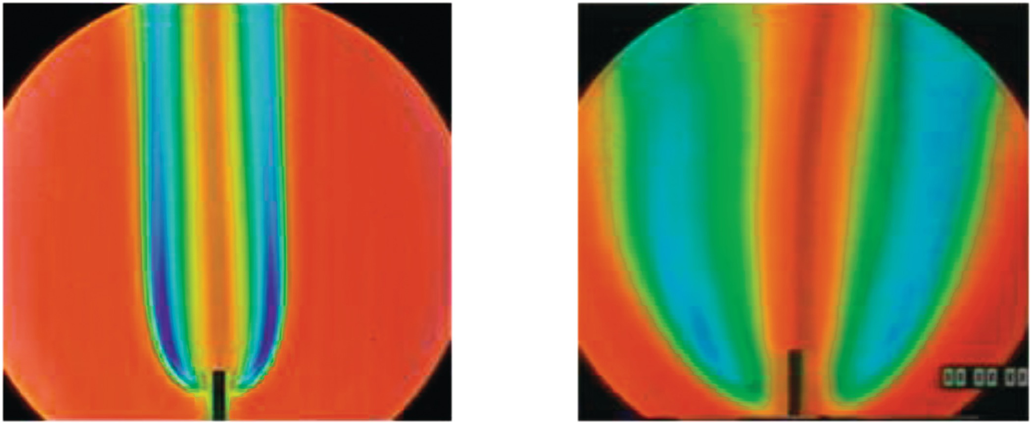
Rainbow schlieren images of laminar diffusion flames of hydrogen issuing from a small circular tube of (1.2 mm diameter) are shown in normal gravity (left) and microgravity (right). The fuel jet Reynolds number is about 100. Images were obtained in the 2.2 s drop tower at NASA Glenn Research Center. Hydrogen flames are visually transparent, but they can be detected using the schlieren technique which is sensitive to density gradients in the flow field. In rainbow schlieren, the density gradients are color-coded by replacing the knife-edge by a continuously graded color filter.
Gravity has a significant effect on the flame structure. In normal gravity, the flame is narrow with large color variations indicating large density gradients. In microgravity, the flame is much wider with gradual color changes indicating smaller density gradients. The images can be analyzed to infer the local temperature field across the whole field of view.
This research was partially funded by NASA Microgravity Combustion program.
Reference
1.1.5 Shadowgraph of Methane Air Flames at Various Turbulent Intensities

Shadowgraph images of premixed methane air flames on a stabilized burner with equivalence ratio of 1.0 and increasing turbulent intensities ranging from 0.024 m/s to 0.532 m/s are shown.
This research was partially funded by NSF GRFP award.
Reference
1.2 Laboratory and/or Idealized Flames
1.2.1 Laminar Methane Stagnation Flame with Seeding Particles Illuminated by a Laser Sheet

Laminar methane-air flame stabilized in a jet-wall stagnation flow, with the flow issuing from the nozzle visible at the bottom of the image. The stagnation flame is visible because of chemiluminescence from the methylidine radical, CH, at wavelengths near 430 nm in the violet part of the visible spectrum. Micron-sized aluminum oxide particles are seeded in the flow and illuminated with a Nd:YAG laser at 532 nm. The laser also illuminates the water-cooled stagnation plate at the top of the image and the fuel-air and co-flow nozzles at the bottom of the image. The seeding density in this image is much higher than would be required for particle-image velocimetry or particle-tracking velocimetry diagnostics, in order to clearly visualize the flow field. Blackbody radiation from the inert seeding particles in the post-flame zone shows the shape of the high-temperature zone and the drop in the gas temperature towards the cooled stagnation plate is also visible.
1.2.2 Flow Visualization in an Oxy/Fuel Counterflow Burner

Flow visualization experiments (FVEs) were implemented in a counter-flow burner to provide visible flow patterns generating a profile in the empty space between the two opposing nozzles that resembles a typical 1-D flame. In this work FVEs are conducted by introducing solid spherical particles in the air flow and by illuminating them as they are carried by the air flow in the space between the burner nozzles.
As the oxygen content in the oxidizer stream was increased, the blue zone became thicker while the overall flame was compressed (Image-F). The maximum temperature and the stagnation plane shifted towards the fuel side and the high temperature region was expanded as the oxygen content was increased. Image-G shows the flame structure as the strain rate is varied for fixed oxygen content of 35%. The strain rate of 10s−1 has the largest yellow zone; as the strain rate increased, the yellow zone decreased. The blue zone and the overall thickness of the flame also decreased with an increasing strain rate.
This work was supported by the National Science Foundation.
1.2.3 Laminar Methane Stagnation Flames at Variable Equivalence Ratios

Laminar methane-air flames stabilized in a jet-wall stagnation flow at varying fuel-air equivalence ratios, Φ. Lean flames, with Φ < 1, have a violet color that is the result of chemiluminescent emission of the methylidine radical, CH, at wavelengths near 430nm. As the flames become fuel-rich, with Φ > 1.1, the flames increasingly turn to a green-blue color that results from emissions of the C2 Swan bands, which emit light from 430 to 650 nm.
This work was funded by the Air Force Office of Scientific Research under grant F49620-01-1-0006.
Reference
1.2.4 Differential Diffusion Effects in Hydrogen-Enriched Laminar Methane Flame at an Equivalence Ratio of 0.8
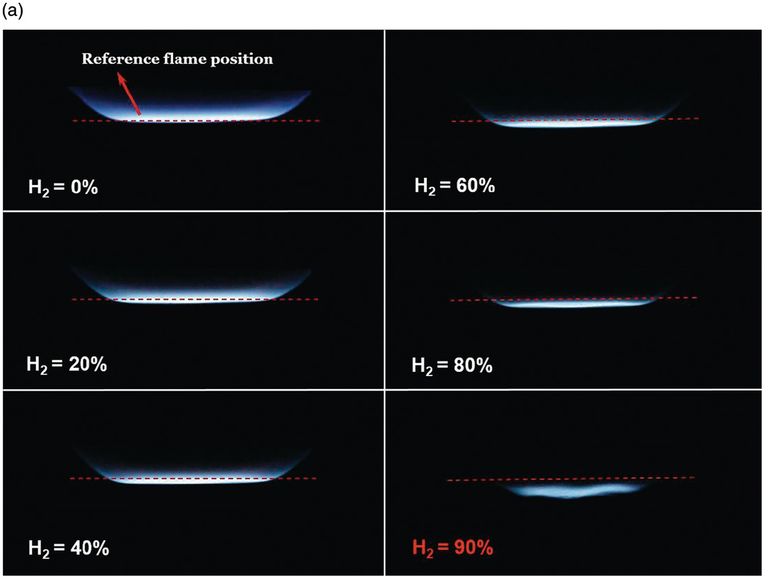
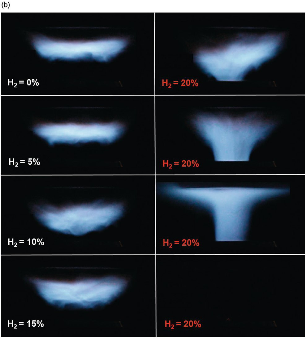
The effects of differential diffusion in premixed flames are shown in a hydrogen-enriched methane-air flame at equivalence ratio of 0.8. By increasing the hydrogen content in the fuel, the Lewis number of the fuel and air mixture is reduced, and the mixture becomes more sensitive to differential diffusion effects.
The left images show a laminar flame stretched mostly due to the bulk strain rate. As the hydrogen content is increased, the flames are observed to move upstream, towards the unburned mixture. In a stagnation flame, this is direct visual evidence that the stretched flame speed is increasing, while the unstretched laminar flame speed is held constant. Finally, the flame becomes unstable and close to flashback at 90% hydrogen content.
In the turbulent case (right side), flame stretch is not only due to the bulk stain rate, but also due to the curvature effects of the turbulent eddies in the flow. Therefore, as seen in the image, the turbulent flame is more sensitive to the effects of differential diffusion. It is illustrated that by increasing hydrogen content of the fuel, the flame is burning faster and moves upstream into the unburned reactants, and consequently, flash back occurs at hydrogen content of 20%, which is much lower than in the laminar case.
This research was funded by the Natural Sciences and Engineering Research Council of Canada and Siemens Canada under the Collaborative Research and Development program.
1.2.5 Two-Dimensional Imaging of the Temperature Field in Laminar Low-Pressure Premixed Flames

The left-side image shows the experimental set-up used at the 7BM beamline of the Advanced Photon Source of the Argonne National Laboratory to measure the two-dimensional temperature field in laminar low-pressure premixed fuel-rich (stoichiometry of 1.7) ethylene (C2H4)/O2/Ar/Kr flame with a cold gas composition by volume of 14.5% C2H4, 22.5% O2, 55% Ar and 5% Kr at a total flow rate of 4 slm. The pressure was kept at 30 Torr. The flame appears in yellow because of the polyimide windows used for the X-ray experiments. The experiments used X-ray florescence spectroscopy to measure the concentration of Kr atoms and hence determine the local temperature in the flame at each measurement location. A highly focused beam (waist 6×7 µm) of 15keV X-rays was used to excite the Kr atoms. The kα florescence photons were collected orthogonal to the X-ray beam by confocal microscopy from a volume (300×6×7 µm) allowing detailed maps of the temperature field to be obtained and the extent to which a probe inserted into the flame distorts the temperature field to be determined.
The smaller images (right side) show a close-up of the burner-stabilized flame, a schematic of the experimental set-up, and some results of measurements of the temperature around a sampling probe.
This material is based upon work supported by the U.S. Department of Energy (DOE), Office of Science, Office of Basic Energy Sciences.
Reference
1.2.6 Aerodynamically Stabilized Laminar Flames at Various Equivalence Ratios and Bulk Strain Rates


Lean premixed flames are stabilized in the Hot exhaust Counter-flow Turbulent flame Rig (HCTR) at various equivalence ratios and turbulence intensities. The rig is designed to stabilize laminar and turbulent flames against a hot product flow in an axial opposed-flow configuration. A co-flow of inert gas is used to reduce the effect of the shear layer that is formed between the inner flows and the ambient air and shrouds the opposed flow from surrounding air.
In left images, laminar flames are stabilized against hot products at equivalence ratios ranging from 0.6 to 0.9, and the bulk flow velocity at the premixed fuel and air nozzle exit ranges from 1m/s to 3 m/s. Right images show stabilized turbulent flames against hot products at various bulk flow velocities and turbulence intensities ranging from weakly wrinkling flames to turbulent flames in the thin reaction zone regime (top to bottom). Increasing the bulk flow velocity at the premixed fuel and air nozzle exit, which ranges from 1m/s to 5m/s, increases turbulence intensity in these tests.
This research was funded by the Natural Sciences and Engineering Research Council of Canada and Siemens Canada under the Collaborative Research and Development program.
1.2.7 Tulip Flame and Distorted Tulip Flames in Experiments and Numerical Simulations


The first row shows a sequence of schlieren images illustrating the development of tulip flame and distorted tulip flames in experiments. The second row shows schlieren images taken from numerical simulations. Both the experiment and the simulation show that the flame shape first changes from convex to concave, and then to a tulip flame, and then distorted tulip flames. The distorted tulip flames develops into a triple tulip flame as the secondary cusps approach the center of the primary tulip flame lips (at 7.8 ms in experiments and 9.033 ms in simulations). A second distorted tulip flame is generated with a cascade of distortions superimposed on the primary lips (at 9.0 ms in experiments and 10.571 ms in simulations) before the disappearance of the first distorted tulip flame.
1.2.8 Transition in a Turbulent Flame

The series of eleven n-heptane/air flames demonstrate the transition that occurs in a turbulent flame as a result of low-temperature oxidation of the reactants prior to their introduction into the high-temperature flame. Scanning left to right, the degree of pre-flame reactant oxidation is increased by increasing the reactant temperature and/or the heated residence time. This transition, evident by the blossoming redness of the flames, can have serious implications on the flame properties, including burning rates, emissions, turbulent/combustion interactions, and flame regimes.
1.2.9 Flame Propagation in Narrow Channels at Varying Lewis Number

A Hele-Shaw cell is used for this laminar flame instability experiment. Dimensions of entire visible area are 40.0 cm by 60 cm. The Hele-Shaw cell is first evacuated, and then filled with desired premixed gas mixture. The gas mixture is ignited at one end of the cell by three ignition sparks. The flame propagates under constant pressure toward the closed end of the cell with ignition end open to the atmosphere. There is no turbulence pre-ignition in the cell. Light emitted from hot products behind flames is filmed in total darkness at 100 frames per second. The photo is created by collapsing frames of the video. Each frame is separated by equal time intervals. The photo is also colorized base on temperature gradient with low temperature colored in blue, and high temperature colored in green.
Top left to right images: (1) H2-O2-N2 flames at equivalence ratio, ϕ = 2, calculated adiabatic flame temperature, Ta = 1200K, downward propagating, gap between plates, d = 1.27 cm; (2) H2-O2-N2 flames at ϕ = 2, Ta = 1200K, horizontally propagating, d = 1.27 cm; (3) H2-O2-CO2 flames at ϕ = 0.35, Ta = 1050K, downward propagating, d = 1.27 cm.
Bottom left to right horizontally propagating flame image: (1) H2-O2-N2 flames at ϕ = 0.45, Ta = 900K, d = 1.27 cm; (2) H2-O2-N2 flames at ϕ = 0.8, Ta = 1300K, and d = 1.27 cm; (3) H2-O2-N2 flames at ϕ = 0.8, Ta = 1300K, and d = 0.32 cm.
This research was supported by the National Science Foundation under Grant CBET-1236892.
1.3 Practical Flames
1.3.1 Chemiluminescence Image of a Longitudinally Excited Bluff Body Flame Wrinkled by Coherent Vortical Wake Structures

This is a chemiluminescence image of an acoustically forced bluff body flame. The exposure time of the image is 200 microseconds. The image shows a wrinkled flame structure that was produced by varicose (symmetrically shed) vortex structures. This is a demonstration of the velocity-coupled flame response, where acoustic oscillations excite hydrodynamic instabilities, which amplify vortical structures and consequently wrinkle the flame. The combustor was supplied with non-vitiated, non-preheated air. The combustor was operated at atmospheric pressure, at a velocity of 50 m/s and a premixed air/natural gas equivalence ratio of 0.8. The combustor was longitudinally acoustically forced with planar acoustic waves at 515 Hz.
Reference
1.3.2 Overlay of a Filtered Instantaneous OH-PLIF (Blue) Image and Raw Mie Scattering (Yellow) for a Premixed Methane–Air Swirl Flame

This image is a composite of two false-colored images. The yellow color belongs to planar Mie scattering from alumina particles with which the flow was seeded for flow visualization and a stereoscopic particle image velocimetry measurement. The blue color belongs to planar laser induced fluorescence (PLIF) of OH. The Mie scattering data provide a visualization of the vortex structures that dominate the fluid dynamics, and the boundaries of the OH PLIF measurement indicate the premixed flame front position. The two images were measured simultaneously and capture a measurement plane that intersects the combustor centerline. This composite demonstrates the fluid-dynamic wrinkling of the flame that often governs the flame dynamics in swirl stabilized combustors. These images were acquired in a lean premixed combustor operating at atmospheric pressure and a preheat temperature of 450 K.
This research was partially supported by the Air Force Office of Scientific Research under award no. FA9550-16-1-0442.
1.3.3 Porous Inert Media with Stable Methane Flame

This is a lean premixed flame stabilized by two different techniques. The bulk flame in the center is a swirl-stabilized flame and it is surrounded by a ring of flamelets stabilized on the downstream surface of an annular porous insert. Premixed reactants enter the combustor, and the mass flow split between the bulk flame and flamelets is determined by the porous insert geometry. Flamelets provide thermal feedback to the bulk flame to enhance static flame stability without the outer flow recirculation region. Porous insert minimizes interactions among vortical structures and reactions zones to mitigate thermoacoustic instabilities that can occur in such systems without the insert. The flame produces a sound pressure level of 92.1 dB at an equivalence ratio of 0.7, which is about 20 dB lower than the sound produced by a similar flame without the porous insert.
1.4 Spherical Flames
1.4.1 Cellular Instabilities in Outwardly Propagating Flame

Two instability mechanisms are intrinsic to the propagation of laminar premixed flames, namely the hydrodynamics, Darrieus-Landau (DL), instability and the diffusional-thermal (DT) instability. DL instability considers the flame to be infinitely thin and structureless, locally propagating with the (constant) laminar flame speed; cells develop due to the local imbalance in the flame and flow speeds. Consequently, DL instability is either aggravated or moderated with decreasing or increasing flame thickness, respectively, with a wide range of cell sizes exceeding the flame thickness. On the other hand, DT instability considers the imbalance in the thermal and reactant mass diffusivities, which is characterized by their ratio, the mixture’s Lewis number, Le, such that the flame is DT unstable and stable for Le<1 and >1, respectively, while the cell sizes are of the order of the flame thickness and as such are smaller than the DL cells.
Based on the controlling mechanisms described above, DL instability is promoted with increasing system pressure, which reduces the flame thickness, and is relevant to processes within internal combustion engines, while DT instability is promoted if the controlling, deficit reactant is also a light species, as for lean hydrogen/air or rich heavy-hydrocarbon/air mixtures. These features are demonstrated here in the morphologies of spark-ignited outwardly propagating flames in a constant-pressure chamber.
Row 1: the flame sequence does not exhibit any flame wrinkling because the pressure (1 atm) is not high (no DL instability) while the deficit reactant, O2, is also a heavy molecule (Le>1).
Row 2: the flame sequence exhibits DL instability because of the elevated pressure (5 atm.) but not the DT instability (Le>1).
Row 3: the flame sequence does not exhibit DL instability (pressure at 2 atm) but exhibit DT instability because the deficit reactant, H2, is a light molecule (Le<1).
This research was supported by the National Science Foundation.
1.4.2 Growth of Darrieus–Landau Instability in a Large-Scale Spherical Flame

An image sequence of the growth of flame instabilities on a premixed stoichiometric propane-air flame is shown. This experiment was performed under quiescent initial conditions at standard temperature and pressure in a 64 m3 enclosure vented to maintain a constant pressure. The image sequence shows the growing spherical flame at diameters of 0.2, 0.4, 0.6, 0.8, 1.0, and 1.2 m.
Initially, the flame is stabilized by stretch due to the increase in flame radius, reducing the amplitude of any initial disturbance created at the time of ignition. At a radius of 0.2 m, however, the growth of large-scale flame cracks is clearly seen as the flame grows from 0.2 – 0.4 m diameter. At this point, the onset and growth of the Darrieus-Landau instability occurs, where the spontaneous formation of cellular structures appear across the entire flame surface.
This work was funded by FM Global and was performed within the framework of the FM Global Strategic Research Program on Explosions and Material Reactivity.
1.5 Gas Jet and Liquid Flames
1.5.1 Complex Nature of Jet Spray Flame Structure

Left image shows a lifted n-heptane jet spray flame. The fuel injection system is composed of a simplex fuel injector (Danfoss, 1.35 kg/h, 80 degrees, hollow cone) and an external annular, non-swirling air co-flow with an inner and outer diameter of 10 and 20 mm respectively. The diameter of the injector orifice is 200 microns. A continuous laser beam (532 nm) is crossing the flame revealing the fuel droplet density by Mie scattering.
Right side images show instantaneous snapshots of OH-PLIF at 10 Hz in a vertical cross section and reveals the complexity of jet spray flame structure, including different reactive zones: a wrinkled inner reactive zone (IRZ) and a non-premixed outer diffusion zone (ORZ), connected by the flame leading edge. The field of view is 112×112mm² leading to a magnification ratio of 0.2212 mm/pix.
The authors gratefully acknowledge the financial support from the Agence Nationale de la Recherche (ANR) under the project TIMBER ANR-14-CE23-0009.
Reference
1.5.2 Reacting Fuel Spray from a Diesel Injector

Reacting n-heptane spray flame acquired by direct photography. The fuel is injected (from left side) at 100 MPa for 3ms through a customized diesel injector which has a single 100 µm diameter axial hole. The ambient is a continuous flow of air at 3 MPa and 800 K. The image shown was acquired immediately after the end of injection at 3 ms. The injected fuel autoignites approximately 1.8 ms after the start of injection. For scale referencing, a 3 mm diameter thermocouple probe can be seen mounted at the top near the injector inlet.
1.5.3 Boilover of a Crude Oil Pool Fire Burning on Water

Boilover of a crude oil pool fire on water (contained in a Pyrex glass cylinder with a diameter of 0.16 m). The water inside the Pyrex glass cylinder is trapped below the burning oil (top left), thus preventing the water from vaporizing as it gets heated up. This causes the water to superheat to a temperature of 120 to 150 °C, at which point the water violently evaporates through the oil slick, ejecting steam and oil droplets into the flame (bottom left). The explosive nature of steam and oil droplets inside the flame cause a chain reaction that drastically increases the burning rate and flame height of the oil, known as boilover (right).
The project was funded by the Danish Council for Independent Research Grant DDF – 1335-00282.
1.6 Flames at High Speed
1.6.1 Combustion of Hydrogen and Fluorine in a Supersonic Shear Layer at Mach 2.5

The top image is a composite schlieren image stitched together from three experimental runs. The bottom image shows a visible image of the chemiluminescence that results from the reacting hydrogen-fluorine shear layer under the same flow and combustion conditions. The chemiluminescence image is taken with a perspective looking upstream, and the test chamber geometry is indicated by the white lines.
The top-stream flow has a Mach number of 2.5, corresponding to a velocity of 570 m/s, and a composition of 19.75% hydrogen and 0.5% nitric oxide in a bulk of nitrogen. The secondary bottom-stream flow issues from a perforated plate, aligned at an angle at the lower left of the images, at a speed of 60 m/s. The bottom-stream flow contains 5% fluorine in a bulk of nitrogen. The reaction rate between fluorine and hydrogen, catalyzed by nitric oxide, is much faster than the characteristic mixing rates, enabling the reaction to be used to measure molecular mixing rates.
The reflecting expansion and shock waves, characteristic of the supersonic Mach 2.5 flow, are visible in the top stream in the schlieren image. The growth of the compressible turbulent boundary layer along the top wall of the facility can be noticed. The reacting shear layer, between the hydrogen and fluorine, is visible in both images. In the composite Schlieren image, the peak temperature location in the shear layer is indicated by the transition from relatively dark to bright intensity. This effect is more distinct at the left of the image since the strong turbulence reduces the temperature gradients in the downstream direction. A rake of pitot probes and thermocouples are visible at the right-hand side of each image.
This work was funded by the AFOSR under Grants FA9550-04-1-0020 and FA9550-04-1-0389.
Reference
1.7 Coal and Solid Particle Flames
1.7.1 Combustion Behavior of Single Particles from Three Different Coal Ranks and from Biomass


Selected images from high-speed cinematography of typical combustion events involving particles of five fuels (bituminous, sub-bituminous, two lignite coals and sugarcane bagasse biomass) free-falling in an electrically-heated laminar-flow transparent drop-tube furnace. Particle sizes were in the range of 74–90 μm and the furnace was operated under atmospheric conditions and a wall temperature set to 1400 K (Tgas approx. 1350 K). The diameter of the wire shown in sequence (a) is 250 μm. The displayed numbers in each frame are in milliseconds, where zero represents beginning of the depicted sequence.
In the case of the sub-bituminous coal two sequences are included, one where volatile flame was present (top), and one where it was absent (bottom). In the depicted frames of the Beulah lignite two particles ignite and burn in similar fashion. (a) bituminous coal (Pittsburgh #8, Pennsylvania, PSOC-1451), (b) sub-bituminous coal (Wyodak, Wyoming, DECS-26), (c) lignite coal (Beulah, North Dakota, DECS-11), (d) lignite coal (Wilcox, Texas, PSOC-1443), and (e) sugarcane bagasse biomass (Brazil).
The authors acknowledge financial assistance from the NSF award CBET-0755431.
Reference
1.7.2 Coal Dust Passing through a Premixed Methane/Air Flame

Image of a premixed turbulent methane air flame with coal particles passing through on a stabilized burner is shown. The coal particles are 75-125 microns in diameter with a concentration less than 25 g/m3. The images were taken after tests conducted at coal dust feed rates of 25 g/m3 and what is burning in this picture are the residual coal particles continuing to flow through the feed system. At higher feed rates the premixed methane air flame is not visible through the bright illumination from the coal particles.
Reference
1.7.3 Aluminum–Methane/air Flame Coupling

Bunsen burner flames are shown of aluminum suspensions (Sauter-mean diameter of 5.6 µm) dispersed in stoichiometric methane/air (21% O2/79% N2) gas mixtures and stabilized at different concentrations of aluminum powder. The figure shows the change in flame structure as the aluminum concentration is raised. At low mass concentrations, below 100 g/m3, the flame appears orange in color and looks the same as a flame seeded with inert SiC powder. This indicates that the aluminum does not ignite at low concentrations. As the concentration of aluminum particles increases to roughly 120–140 g/m3, a bright white spot emerges first at the tip of the flame and, as the concentration increases further to about 180 g/m3, a very bright front with a well-defined outer border indicating aluminum combustion moves down along the flame cone, eventually stabilizing just a few millimeters above the rim of the methane flame. The bright white color of the flame results from the high temperatures (~3500K) of the aluminum flame and chemiluminescent emissions from aluminum oxide.
This research was supported by Natural Sciences and Engineering Research Council of Canada and Martec, Ltd., and Defense Threat Reduction Agency under contract HDTRA 1-11-1-0014.
References
1.7.4 Double Front Structure of Methane–Iron/Air Flames

The photograph shows a stabilized Bunsen iron-methane-air flame. The picture illustrates the double front structure obtained in hybrid metal-hydrocarbon systems. The first front is the methane-air flame. The second front, coupled to the first one, is the iron front, burning in the products of combustion of the methane flame (water and carbon dioxide) at around 2200 K. The methane-air mixture has an equivalence ratio of 1, with no oxygen available for iron combustion, forcing it to burn with steam and carbon dioxide. The iron concentration of the particles (d32 = 2.20 μm) is around 160 g/m3.
Reference
1.7.5 Aluminum–Methane/Air Dual-Front Flame Decoupling and Recoupling

Series of frames illustrating the propagation, quenching, and reestablishment of dual-front flames in a suspension of aluminum particles in a premixed methane-oxidizer mixture. The experiment is performed in tubes of diameter of 48 mm, within which are placed a set of quenching channels, formed by equally-spaced plates. The tests are performed in mixtures of aluminum suspensions (d32 = 5.6 μm) in a methane/oxygen/nitrogen gas (16.3% O2/8.1% CH4/75.6% N2). Upon reaching the small channels, the aluminum-methane flame decouples and only the dim orange front, corresponding to the methane-oxygen reaction, propagates through the channels. Soon after the flame emerges back into the tube, the aluminum front forms again in the wake of the methane front and both fronts thermally re-couple. The aluminum concentration in the image is about 400 g/m3.
Supported by Natural Sciences and Engineering Research Council of Canada and Martec, Ltd. (Collaborative Research and Development Grant) and Defense Threat Reduction Agency under contract HDTRA 1-11-1-0014.
Reference
1.8 Metal Power Flames
1.8.1 Flames of Different Metal Powders Burning in Air

The pictures show 5 different flames stabilized on a laminar metal-fuel burner. The first flame is a methane flame, similar to that stabilized on a standard Bunsen burner. Flames of various metal powders suspended in air and other oxidizing gases are shown in the following four frames.
Support for this work was provided by the Natural Sciences and Engineering Research Council of Canada.
Reference
1.8.2 Pulsating Aluminum Flame

The pictures show two periods of a pulsating aluminum flame. The laminar flame is freely-propagating inside a 30 cm latex balloon. The pulsations arise from thermo-diffusive instabilities. The flame is propagating in a gaseous mixture of 40% oxygen and 60% argon. The aluminum concentration is on the order of 300 g/m3, which corresponds to an equivalence ratio of 0.5, and the particle Sauter mean diameter is 5.6 μm.
Supported by Natural Sciences and Engineering Research Council of Canada and Martec, Ltd. (Collaborative Research and Development Grant) and Defense Threat Reduction Agency under contract HDTRA 1-11-1-0014.
References
1.8.3 Aluminum/Air Flames

The pictures show 5 different aluminum flames. In all cases, the particle size is around 6 μm, and all flames are fuel rich (equivalence ratio greater than one). The figures show pure aluminum-air flames, in different geometric configurations. The configurations are the following: a) Bunsen flame, b) aluminum flame in a tube, c) spherically-propagating aluminum flame, d) flat, counter-flow aluminum flame, e) Still frames of a large-scale (2 m width, 4 m height), cylindrical aluminum flame.
Support for this work was provided by the Natural Sciences and Engineering Research Council of Canada and Martec, Ltd., under a Collaborative Research and Development Grant, and the Defense Threat Reduction Agency under contract HDTRA1-11-1-0014.