Abstract
Combustion is ubiquitous around us and in the technology that we depend on in our daily lives. To someone uninitiated in the field, observing the combustion process can produce emotions ranging from apathy, fear, boredom, conservatism, or caution to outright joy, including love and affection. Observing combustion is also a great source of fascination to many, in particular to scientists and engineers, who seek to understand the intricate relationships among the chemical, thermal, fluid dynamic, and other complex phenomena involved in the combustion process. The wide variety of fuel and oxidizers, operating conditions such as initial temperature, pressure, and concentrations, and combustor geometry configurations create virtually limitless combinations of combustion, observed visually as flame(s). For example, flames of gaseous, liquid, and solid fuels share many similarities, but they also exhibit their own unique features. Flames do not depict all of their features naturally, and thus researchers employ various diagnostics techniques, often laser-based, to measure one or more characteristics, which can also unravel the mysteries of soot, nitric oxide, and carbon oxide formation, and/or help address various safety-related issues such as flame flashback, flame blow-off, flame noise, etc. The ultimate goal of such explorations is to develop clean combustion systems that are fuel agnostic, highly efficient, and, most importantly, environmentally friendly, i.e., they produce low or very low levels of harmful emissions, including greenhouse gas emissions. This chapter presents simple canonical flames, free from the complexities of most practical combustion systems, to offer insight into the key phenomena. This chapter is divided into eight sections, each covering a different aspect of laboratory-scale flames.
Introduction
Combustion is ubiquitous around us and in the technology that we depend on in our daily lives. To someone uninitiated in the field, observing the combustion process can produce emotions ranging from apathy, fear, boredom, conservatism, or caution to outright joy, including love and affection. Observing combustion is also a great source of fascination to many, in particular to scientists and engineers, who seek to understand the intricate relationships among the chemical, thermal, fluid dynamic, and other complex phenomena involved in the combustion process. The wide variety of fuel and oxidizers, operating conditions such as initial temperature, pressure, and concentrations, and combustor geometry configurations create virtually limitless combinations of combustion, observed visually as flame(s). For example, flames of gaseous, liquid, and solid fuels share many similarities, but they also exhibit their own unique features. Flames do not depict all of their features naturally, and thus researchers employ various diagnostics techniques, often laser-based, to measure one or more characteristics, which can also unravel the mysteries of soot, nitric oxide, and carbon oxide formation, and/or help address various safety-related issues such as flame flashback, flame blow-off, flame noise, etc. The ultimate goal of such explorations is to develop clean combustion systems that are fuel agnostic, highly efficient, and, most importantly, environmentally friendly, i.e., they produce low or very low levels of harmful emissions, including greenhouse gas emissions. This chapter presents simple canonical flames, free from the complexities of most practical combustion systems, to offer insight into the key phenomena. This chapter is divided into eight sections, each covering a different aspect of laboratory-scale flames.
The first section contains images of (1) laminar diffusion flames to illustrate how shape and sooting tendencies are affected by the oxidizer flow rate in a simple Burke–Schuman burner as shown in Figure 1.1; (2) a premixed methane–air flame exhibiting blue color distinct from the yellow color of diffusion flames as shown in Figure 1.2; and (3) a triple flame comprised of both diffusion and premixed flames in a single flame. The flames widen when gravity-induced buoyancy is removed, as shown in Figures 1.3 and 1.4. Figure 1.5 shows a well-defined conical reaction zone in a premixed flame, which can become corrugated by the presence of turbulence in the reactant flow. Images illustrate various phenomena captured by multiple observational techniques, including shadowgraph and color schlieren.
The images in Section 1.2 show one of the simplest flame configuration, the so-called one-dimensional flame obtained in a counterflow burner configuration. Images show how flame thickness, flame position, flame color, and/or flame luminosity are all affected by the oxidizer, equivalence ratio, hydrogen enrichment, strain rates, etc. Tulip flames obtained experimentally and computationally are shown in Figure 1.12. Transition in turbulent flames and flame propagation in narrow channels are illustrated next.
Figures 1.15 and 1.16 show vortical structures associated with noise generation in flames. The flame structure and its noise characteristics can be improved by introducing a porous structure within the combustor as shown in Figure 1.17.
Section 1.4 presents spherical flames created by locally igniting the reactant mixture. As the flame propagates radially, and the flame front increases in size, the cellular instabilities are formed and can be clearly observed.
Section 1.5 presents examples of liquid flames, produced either by injecting the fuel into the oxidizer or by allowing the fuel to find the oxidizer, such as in pool fires.
Section 1.6 presents an example of combustion at supersonic conditions.
Combustion of coal particles, one of the most prevalent solid fuel in use, is illustrated in Section 1.7. Coal can be burned alone or in combination with other gaseous fuels. Figures 1.26–1.28 show that metals can also burn when introduced in typical methane–air flames, and produces interesting features.
Section 1.8 shows that different metal powders and/or metals burning in air exhibit similarity to gaseous fuel combustion.

1.1 Different Types of Simple Flames
1.1.1 Overventilated and Underventilated Axisymmetric Laminar Diffusion Flames in a Burke–Schumann Burner
Overventilated (left) and underventilated (right) laminar diffusion flames are shown. Overventilated flames are closed on the axis of symmetry of the burner while underventilated flames are open and terminate over the external oxidant tube. The two types of flame can be obtained keeping the flow momentum of the reactants equal and by changing the fuel tube radius, a, the Peclet number, Pe, or the initial mass fraction of oxygen in air, YO0. Furthermore, they can be obtained by varying the mass flow rates of one of the reactants and keeping constant the flow rate of the other.
The left image shows an overventilated CH4/air flame, with a = 3 mm and fuel velocity of 550 mm/s obtained in the visible spectrum as well as with optical filters for C2 and CH radicals detection. The right image shows an underventilated CH4/air flame obtained by keeping constant the mass flow rate of CH4 while reducing the mass flow rate of air in the visible spectrum and with optical filters for C2 and CH radicals detection.
This research was partially funded by CAPES Brazilian Research Support Agency.
Reference
1.1.2 Crossed Slot Burner – Premixed Methane Air – Near Blow-off
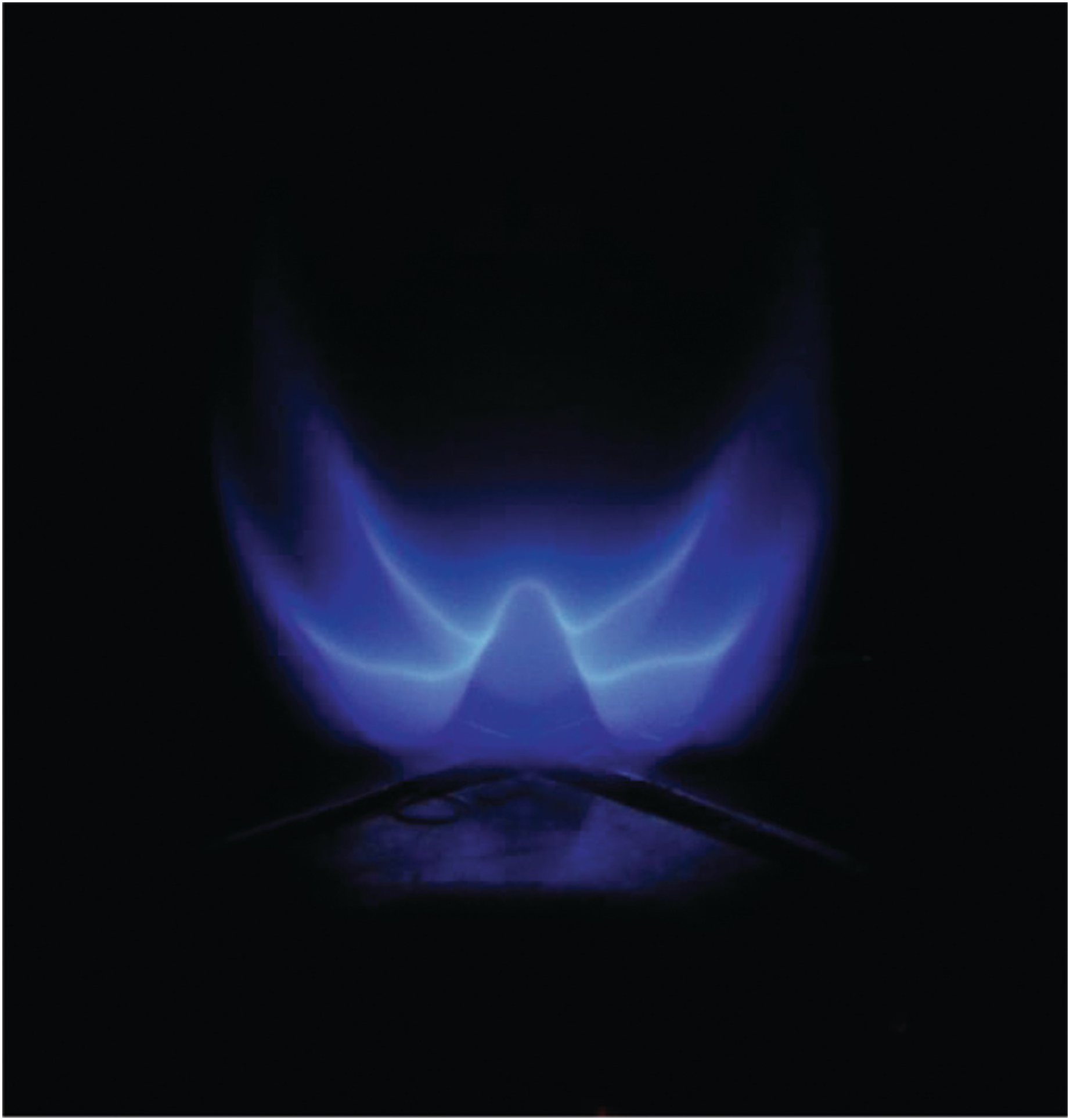
This image is of a premixed methane air flame on a steady-state slot burner. The slots are in the shape of a cross on top of a circular cap. The equivalence ratio is near stoichiometric, and the flow rate is high enough that the edges of the flame lift off of the burner while the center core remains anchored.
1.1.3 Laminar Triple Flames at Normal Gravity and Microgravity

The left-side contains direct images of methane triple flames under normal (1g) and microgravity (μg) established on a Wolfhard–Parker slot burner by introducing a fuel rich methane-air mixture from an inner slot and a fuel lean mixture from two symmetric outer slots. A triple flame is characterized by three reaction zones. Two premixed reaction zones (one fuel–rich on the inside and the other fuel–lean on the outside) form the exterior “wings”of the flame, and a nonpremixed reaction zone is established in between the two wings. While the inner rich premixed zone is only weakly affected by gravity, the outer lean premixed zone and the nonpremixed zone are noticeably influenced by buoyancy.
The right-side image compares the computed and measured triple flames in terms of the computed volumetric heat release rates and the experimentally measured C2*-chemiluminescence intensities. While all three reaction zones are clearly visible in the computed heat release rate contours, the lean premixed reaction zone is not quite as evident in the experimental image, since the fuel lean chemistry is not captured by C2*-chemiluminescence.
This research was partially funded by National Science Foundation (NSF) and by NASA Microgravity Combustion program.
Reference
1.1.4 Rainbow Schlieren Image of Laminar Hydrogen Jet Diffusion Flame in Normal Gravity (Left) and Microgravity (Right)
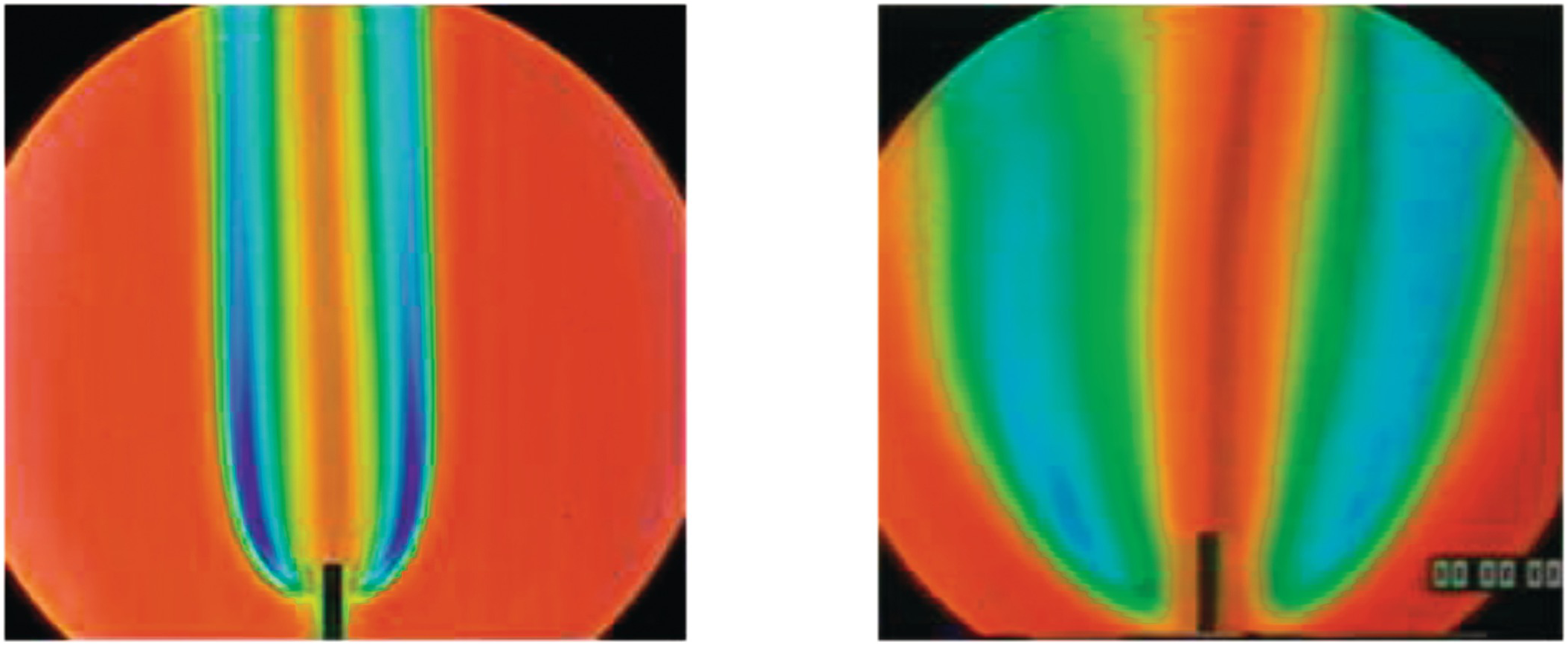
Rainbow schlieren images of laminar diffusion flames of hydrogen issuing from a small circular tube of (1.2 mm diameter) are shown in normal gravity (left) and microgravity (right). The fuel jet Reynolds number is about 100. Images were obtained in the 2.2 s drop tower at NASA Glenn Research Center. Hydrogen flames are visually transparent, but they can be detected using the schlieren technique which is sensitive to density gradients in the flow field. In rainbow schlieren, the density gradients are color-coded by replacing the knife-edge by a continuously graded color filter.
Gravity has a significant effect on the flame structure. In normal gravity, the flame is narrow with large color variations indicating large density gradients. In microgravity, the flame is much wider with gradual color changes indicating smaller density gradients. The images can be analyzed to infer the local temperature field across the whole field of view.
This research was partially funded by NASA Microgravity Combustion program.
Reference
1.1.5 Shadowgraph of Methane Air Flames at Various Turbulent Intensities

Shadowgraph images of premixed methane air flames on a stabilized burner with equivalence ratio of 1.0 and increasing turbulent intensities ranging from 0.024 m/s to 0.532 m/s are shown.
This research was partially funded by NSF GRFP award.
Reference
1.2 Laboratory and/or Idealized Flames
1.2.1 Laminar Methane Stagnation Flame with Seeding Particles Illuminated by a Laser Sheet

Laminar methane-air flame stabilized in a jet-wall stagnation flow, with the flow issuing from the nozzle visible at the bottom of the image. The stagnation flame is visible because of chemiluminescence from the methylidine radical, CH, at wavelengths near 430 nm in the violet part of the visible spectrum. Micron-sized aluminum oxide particles are seeded in the flow and illuminated with a Nd:YAG laser at 532 nm. The laser also illuminates the water-cooled stagnation plate at the top of the image and the fuel-air and co-flow nozzles at the bottom of the image. The seeding density in this image is much higher than would be required for particle-image velocimetry or particle-tracking velocimetry diagnostics, in order to clearly visualize the flow field. Blackbody radiation from the inert seeding particles in the post-flame zone shows the shape of the high-temperature zone and the drop in the gas temperature towards the cooled stagnation plate is also visible.
1.2.2 Flow Visualization in an Oxy/Fuel Counterflow Burner

Flow visualization experiments (FVEs) were implemented in a counter-flow burner to provide visible flow patterns generating a profile in the empty space between the two opposing nozzles that resembles a typical 1-D flame. In this work FVEs are conducted by introducing solid spherical particles in the air flow and by illuminating them as they are carried by the air flow in the space between the burner nozzles.
As the oxygen content in the oxidizer stream was increased, the blue zone became thicker while the overall flame was compressed (Image-F). The maximum temperature and the stagnation plane shifted towards the fuel side and the high temperature region was expanded as the oxygen content was increased. Image-G shows the flame structure as the strain rate is varied for fixed oxygen content of 35%. The strain rate of 10s−1 has the largest yellow zone; as the strain rate increased, the yellow zone decreased. The blue zone and the overall thickness of the flame also decreased with an increasing strain rate.
This work was supported by the National Science Foundation.
1.2.3 Laminar Methane Stagnation Flames at Variable Equivalence Ratios

Laminar methane-air flames stabilized in a jet-wall stagnation flow at varying fuel-air equivalence ratios, Φ. Lean flames, with Φ < 1, have a violet color that is the result of chemiluminescent emission of the methylidine radical, CH, at wavelengths near 430nm. As the flames become fuel-rich, with Φ > 1.1, the flames increasingly turn to a green-blue color that results from emissions of the C2 Swan bands, which emit light from 430 to 650 nm.
This work was funded by the Air Force Office of Scientific Research under grant F49620-01-1-0006.
Reference
1.2.4 Differential Diffusion Effects in Hydrogen-Enriched Laminar Methane Flame at an Equivalence Ratio of 0.8
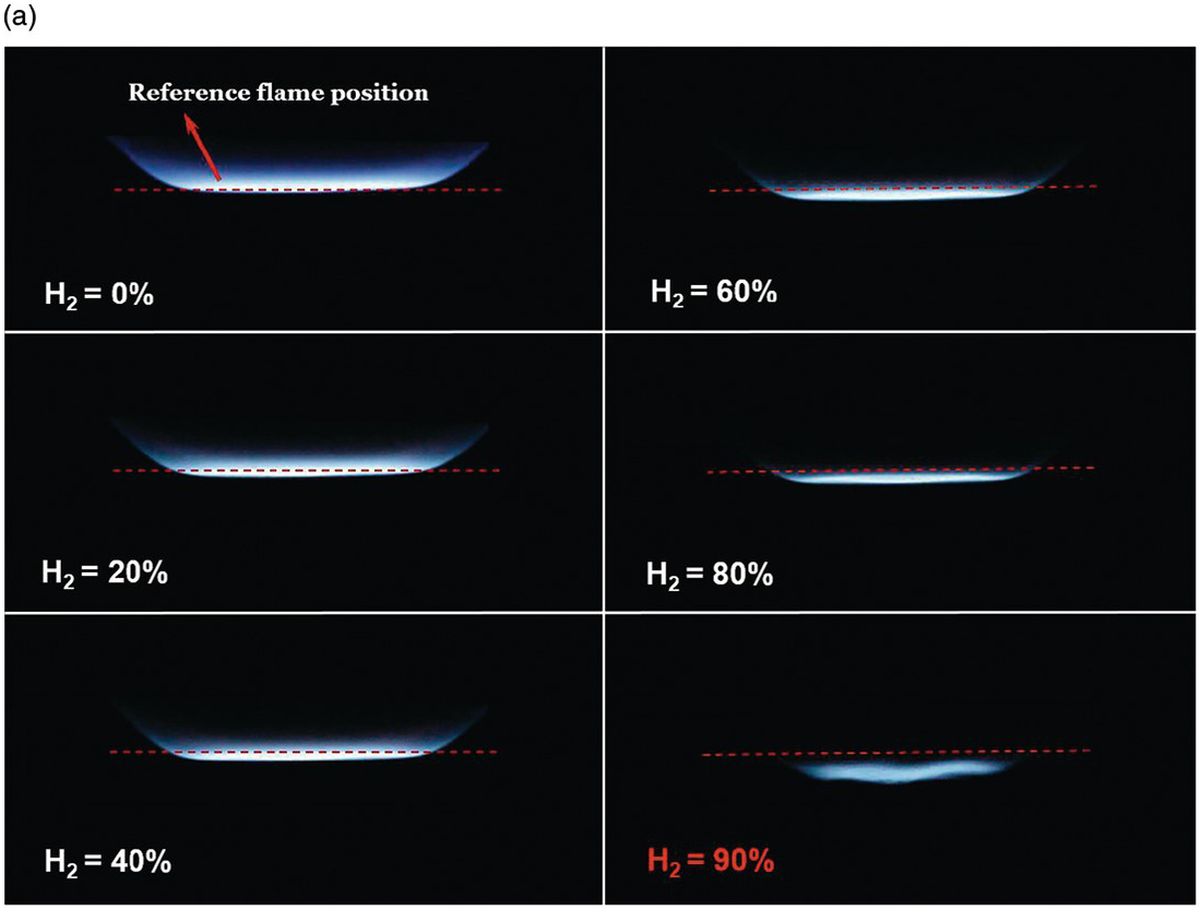
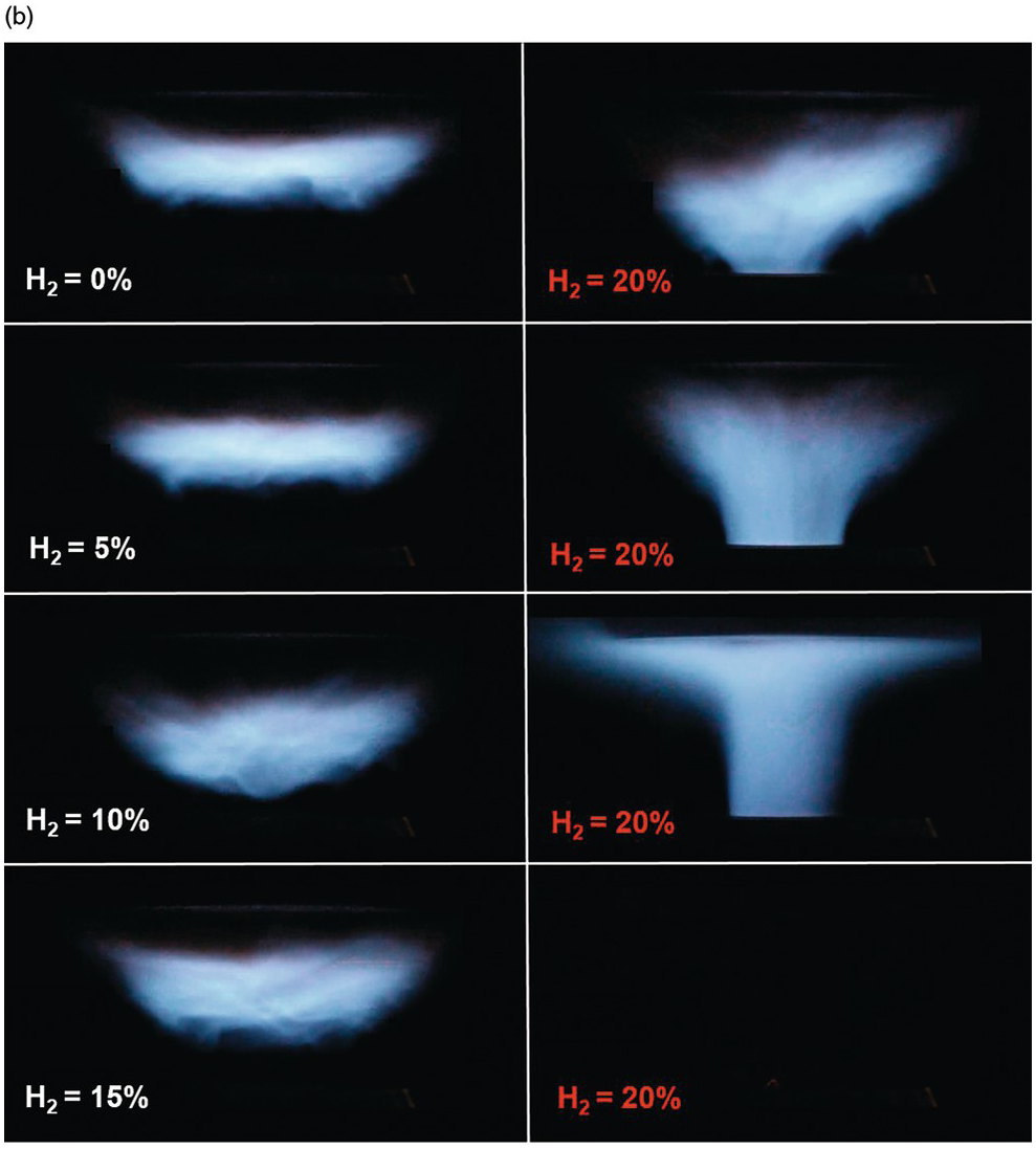
The effects of differential diffusion in premixed flames are shown in a hydrogen-enriched methane-air flame at equivalence ratio of 0.8. By increasing the hydrogen content in the fuel, the Lewis number of the fuel and air mixture is reduced, and the mixture becomes more sensitive to differential diffusion effects.
The left images show a laminar flame stretched mostly due to the bulk strain rate. As the hydrogen content is increased, the flames are observed to move upstream, towards the unburned mixture. In a stagnation flame, this is direct visual evidence that the stretched flame speed is increasing, while the unstretched laminar flame speed is held constant. Finally, the flame becomes unstable and close to flashback at 90% hydrogen content.
In the turbulent case (right side), flame stretch is not only due to the bulk stain rate, but also due to the curvature effects of the turbulent eddies in the flow. Therefore, as seen in the image, the turbulent flame is more sensitive to the effects of differential diffusion. It is illustrated that by increasing hydrogen content of the fuel, the flame is burning faster and moves upstream into the unburned reactants, and consequently, flash back occurs at hydrogen content of 20%, which is much lower than in the laminar case.
This research was funded by the Natural Sciences and Engineering Research Council of Canada and Siemens Canada under the Collaborative Research and Development program.