5.0 Introduction
Sealing technology is critical to modern high-performance gas turbine designs whose internal flow systems involve a variety of static (between stator surfaces) and dynamic (between stator and rotor surfaces) seals. Some of these seals are designed to minimize parasitic leakage flows, while others simultaneously meter the cooling flows as needed for the downstream components under various operating conditions. They endure severe operating and boundary conditions. The key design goals for seals used in gas turbines are: (1) to achieve pressure sealing between stationary and rotating surfaces with minimum leakage flow, (2) to minimally impact turbine and compressor efficiencies, (3) to generate acceptable windage temperature rise across them, (4) to achieve acceptable rotor thrust across them, and (5) to impact rotor dynamics within acceptable limits. Key design parameters that influence each seal performance include seal geometry, drag characteristics of the stator and rotor surfaces; and operating parameters such as inlet pressure, temperature, swirl, seal pressure ratio, fluid viscosity, and leakage flow compressibility.
During a gas turbine operation, as a result of the radial thermal and centrifugal growth of the rotor and the radial thermal growth of the adjacent stator, the seal clearance between them decreases and may lead to interference and excessive material loss through rubbing. These rubs typically result in the permanent removal of effective sealing material, increasing leakage. To avoid a rub, dynamic seals with rigid geometry; for example, straight-through labyrinth seals, inevitably have a larger build clearance. To better accommodate rotor excursions, the performance of other legacy labyrinth seals is improved by having teeth on the rotor and a layer of abradable or honeycomb material on the stator. In contrast, compliant seals track rotor movement with minimal loss of effective sealing material when a rub is experienced. The gas turbine returns to steady-state performance with minimal increase in leakage. Because brush seals can follow rotor movement with minimal wear, they fall into the category of contacting compliant seals, reducing leakage gaps that occur from large thermal differences between rotating and stationary components. The sealing technology used in modern gas turbines is trending toward the development of noncontacting compliant seals.
Chupp et al. (2006, 2014) provide an extensive and authoritative review of standard static and dynamics seals and advanced seal designs used in turbomachinery, including a rich bibliography for those who are interested in further advancing the seal technology. Rotordynamics considerations of seals are extensively presented in Childs (1993). The main thrust of this chapter is on the thermofluids modeling of standard dynamic seals used in gas turbines, enabling the calculation of seal leakage flow rate and the associated windage temperature rise for 1-D flow network simulation of secondary cooling and sealing flows. Toward this objective, we limit our discussion in this chapter to the labyrinth seals. For the other types of seals, the interested readers may refer to the references and bibliography at the end of this chapter.
5.1 Straight-Through and Stepped-Tooth Designs
As the name suggests, a labyrinth seal creates a complex flow passage to increase pressure loss across it and reduces leakage flow rate for a given clearance. Being the most widely used in gas turbines, these seals are inexpensive, noncontacting, and they operate under a wide range of pressures, temperatures, and rotor speeds. Some of their disadvantages include inevitable wear that enlarges clearance and worsens leakage.
Three most commonly used design configurations of a labyrinth seal are schematically shown in Figure 5.1. The straight-through design with nominal labyrinth is the most basic one with nearly equal inlet and outlet radii. Stepped designs are used to handle leakage through an inclined rotor-stator interface, and they offer higher flow resistance than a straight-through design.
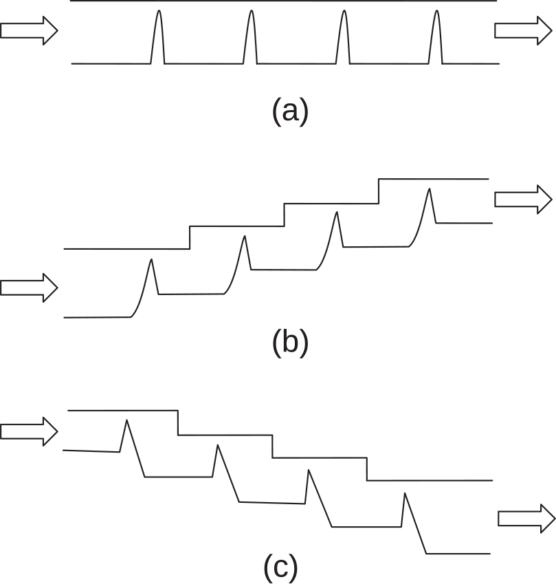
Figure 5.1 (a) Straight-through design, (b) step-up design, and (c) step-down design.
5.1.1 Flow Physics
Figure 5.2a shows typical streamlines in a straight-through labyrinth seal. As the flow jets out the clearance gap between the rotating tooth and stator, it undergoes a sudden radially inward expansion in the downstream pocket formed between two adjacent teeth. The entrainment of the fluid for jet expansion creates flow recirculation in the pocket. Exceptfor rotation, the flow field in each pocket is similar to that of a driven cavity flow. Rotation produces radial pumping along each tooth, generating in each pocket additional shear layers, which are primarily responsible to destroy most of the incoming dynamic pressure, resulting in excess entropy production and loss in total pressure. The wall jet flow along the stator surface (land) suffers minimum loss in dynamic pressure and mainly contributes to the “kinetic energy carry-over factor” for the next tooth passage. An ideal labyrinth seal aims at total loss in dynamic pressure associated with its through-flow into each pocket, enabling a 1-D tube-and-tank modeling of the seal. This makes the seal more predicable in terms of its leakage flow characteristics. For an accurate assessment of the carry-over factor for each seal design, one must resort to either experimental data or high-fidelity 3-D CFD simulation.
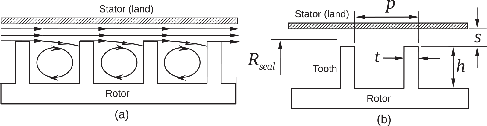
Figure 5.2 (a) Expected streamlines in a straight-through labyrinth seal and (b) seal geometric parameters.
An inevitable consequence of rotation is the generation of windage in the seal as a result of work transfer from the rotor surface. Windage is an undesirable feature of each seal and must be accurately quantified to calculate the rise in coolant air temperature. Air enters each seal pocket at a swirl factor close to 0.5. As a result of the preponderance of rotor surface over the stator surface in each pocket, the air is expected to exit the pocket at a swirl factor greater than 0.5.
5.1.2 Leakage Mass Flow Rate
The well-known formula of Martin (1908) to compute mass flow rate through a multitooth straight-through seal is given by
 (5.1)
(5.1)where CdCd is the discharge coefficient, AA the geometric area available for the seal flow, and ββ the gland factor, which is given by
 (5.2)
(5.2)In Equations 5.1 and 5.2, Pt(0)Pt0 and Tt(0)Tt0 are the total pressure and total temperature, respectively, at the inlet, and Ps(n)Psn is the static pressure at the exit of the seal with nn teeth. Martin’s formula assumes that the flow throughout the seal is subsonic, the dynamic pressure through each tooth is completely lost in the downstream cavity, and the total temperature remains nearly constant.
For the seal geometry shown in Figure 5.2b, Egli (1935) proposed the following equation to estimate leakage mass flow rate:
 (5.3)
(5.3)where
Ct≡Ct≡ Seal throttling coefficient
Cc≡Cc≡ Seal carry-over coefficient
Cr≡Cr≡ Seal contraction coefficient
For CtCt, CcCc, and CrCr, Aungier (2000) converted the graphical representations in Egli (1935) into the following easy-to-use equations:
 (5.4)
(5.4) (5.5)
(5.5) (5.6)
(5.6)where
Equations 5.4, 5.5, and 5.6 are shown plotted in Figure 5.3.

Figure 5.3 (a) Seal contraction ratio, (b) seal throttling coefficient, and (c) seal carry-over coefficient.
Vermes (1961) further extended Martin’s work and modified Equation 5.1 to compute leakage flow rate for straight, stepped, and combination seals. In particular, to account for the change in total temperature through the seal as a result of windage, he augmented the numerical coefficient from 5.68 to 5.76 in Equation 5.1. Furthermore, using Zabriskie and Sternlicht (1959), he proposed the following modified leakage equation:
 (5.7)
(5.7)where αα is called the kinetic energy carry-over factor, which is related to seal geometry. With the aid of the boundary layer analysis, he proposed the following equation to compute αα:
 (5.8)
(5.8)where pp is the seal pitch, bb the tooth tip width, and ss the seal clearance. Note that the seal flow total temperature can only be changed either by heat transfer or windage (work transfer), and it should not depend upon the kinetic energy carry-over factor. Only for an incompressible flow, the dynamic pressure, which equals 0.5ρV20.5ρV2, can be interpreted as the flow kinetic energy per unit volume.
For the seal geometry shown in Figure 5.4a, McGreehan and Ko (1989) proposed the following leakage mass flow rate equation, which is a modified form of Equation 5.7:
 (5.9)
(5.9)where KLKL is the seal configuration factor, which is like an overall discharge coefficient for the seal.

For the seal geometry shown in Figure 5.4b, Zimmermann and Wolff (1998) proposed the following seal mass flow rate equation:
 (5.10)
where CdCd is the discharge coefficient, and k2k2, the corrected carry-over coefficient given by k2 = kk1k2=kk1, where the carry-over coefficient kk, first proposed by Hodkinson (1939), is expressed in terms of seal geometry as
 (5.11)
and the correction factor k1k1 is given by
 (5.12)
Equations 5.11 and 5.12 are shown plotted in Figure 5.5a and 5.5b, respectively. While the variations of the carry-over coefficient kk shown in Figure 5.11a exhibit acceptable tends for a seal with the number of teeth ranging from 2 to 15, the corrected carry-over coefficient k2k2 shown in Figure 5.5c seems suspect for 0 < s/p < 0.080<s/p<0.08. Note that both kk and k2k2 are akin to CcCc used in Equation 5.3, which is shown in Figure 5.3c.

Figure 5.5 (a) Seal carry-over coefficient k1k1, (b) correction factor kk, and (c) corrected carry-over coefficient k2k2.
5.2 Tooth-by-Tooth Modeling
Various empirical correlations proposed in the foregoing section generally compute significantly different values (see Problem 5.1) for the seal leakage mass flow rate. This is to be expected as the leakage mass flow rate depends on both the seal operating conditions and various geometric features, which are difficult to accurately capture in a universal empirical correlation. Furthermore, these correlations do not explicitly account for the swirl velocity variation and windage temperature rise in these seals, somewhat impacting their leakage mass flow rate. Nevertheless, these empirical correlations are still valuable in providing an initial estimate of the leakage mass flow rate to enable an iterative solution method based on the tooth-by-tooth distributed modeling of the labyrinth seal discussed next in this section.
The tooth-by-tooth distributed modeling of a six-tooth labyrinth seal is schematically shown in Figure 5.6. This modeling methodology from seal inlet to outlet allows us to incorporate seal geometry variations, changes in total temperature as a result of both heat transfer and windage, and forced vortex pressure changes as a result of the change in radius between two adjacent teeth, as found in a stepped labyrinth seal design. The prediction results in this case include not only the seal leakage mass flow rate but also the total temperature and swirl factor at the seal exit.

Figure 5.6 Tooth-by-tooth modeling of a six-tooth labyrinth seal.
For an incompressible flow, the mass flow rate at a section depends on the difference between the total pressure and static pressure at the section. In case of a compressible flow, however, the mass flow rate depends upon both the total pressure and total-to-static pressure ratio, and the seal may feature a choked flow condition if the Mach number over a tooth becomes unity. For a labyrinth seal with uniform clearance across each tooth, we can make the following argument that the seal can only choke at the last tooth. In steady state, the mass flow rate remains constant throughout the seal. Over each seal tooth with constant leakage flow area, discharge coefficient, swirl factor, and total temperature, the mass flow rate will be proportional to the total pressure and total-pressure mass flow function, which is a function of Mach number, which in turn is a function of total-to-static pressure ratio (see Chapter 2). When the flow chokes at a section, its Mach number becomes unity, yielding a constant value of the total-pressure mass flow function. Because the total pressure decreases monotonically across the labyrinth seal, the maximum leakage mass flow rate through it must correspond to the minimum total pressure, which occurs at the last tooth.
Let us assume that the six-tooth labyrinth seal shown in Figure 5.6 is operating under ideal conditions such that the entire dynamic pressure generated at each tooth is dissipated in the downstream cavity, implying zero kinetic energy carry-over factor (α = 0α=0). In addition, under adiabatic conditions with no rotation, the total air temperature remains constant throughout the seal. Accordingly, the static pressure in each cavity becomes the total pressure for the flow over the downstream tooth. This implies that the static-pressure mass flow function over one tooth must equal the total-pressure mass flow function over the next tooth, as shown in Figure 5.7a for a choked air flow through the seal. This figure also shows how Mach number increases from seal inlet to outlet. While the air flow remains subsonic from tooth 1 to tooth 5, it increases rapidly to unity over tooth 6, the last tooth. The corresponding variation in total-to-static pressure ratio from tooth 1 to tooth 6 is shown in Figure 5.7b.

Figure 5.7 (a) Mach number variation across a six-tooth choked ideal labyrinth seal and (b) tooth-wise pressure ratio variation across the seal.
The overall total-to-static pressure ratio for a choked air flow through an ideal labyrinth seal varies with the number of teeth. This variation is depicted in Figure 5.8. We can represent the curve in this figure by the following cubic polynomial:
 (5.13)
Figure 5.8 Overall total-to-static pressure ratio variation with nn for the choked flow through an ideal labyrinth seal.
For a labyrinth seal with nn number of teeth, if the overall pressure ratio is equal or higher than that computed by Equation 5.13, the seal flow will choke at the last tooth, and if it is lower, the flow will remain subsonic throughout the seal. For the six-tooth labyrinth seal, the overall critical pressure ratio is exactly calculated to be 3.556, while the curve-fit Equation 5.13 yields 3.564, which is within an acceptable error of 0.23 percent.
5.2.1 Orifice-Cavity Model
For a given labyrinth seal with known geometry, the typical design objective is to calculate the seal leakage mass flow rate when the total pressure, total temperature, and swirl factor are specified at the seal inlet, and the static pressure is specified at the seal outlet. The orifice-cavity model shown in Figure 5.9 forms the basis for the tooth-by-tooth modeling of a multitooth labyrinth seal shown in Figure 5.6. For the rotor-stator cavity control volume, which is formed between two consecutive teeth together with the stator surface, shown in Figure 5.9, we present here a methodology to compute the compressible flow properties at outlet j + 1j+1, knowing their values at inlet jj. Note that, if the seal operates under the choked flow condition, which typically occurs at its last tooth, the specified outlet static pressure boundary condition becomes irrelevant. In this case, we should use M = 1M=1 as the new boundary condition at the last tooth. In steady state, the air leakage mass flow rate over each seal tooth remains constant.

Figure 5.9 Orifice-cavity model control volume formed between tooth j and tooth j + 1 in a multitooth labyrinth seal.
With an initial estimate of the seal leakage mass flow rate ṁ , which may be obtained using any of the empirical equations presented in the previous section, we summarize here an iterative solution method for the orifice-cavity model shown in Figure 5.9.
1. Assume Mach number M(j)Mj and calculate the total-pressure mass flow function at section jj
F̂ftj=Mjκ1+κ−12Mj2κ+1κ−1
2. Knowing the empirical discharge coefficient Cd(j)Cdj, calculate the velocity coefficient CV(j) = Vx(j)/V(j)CVj=Vxj/Vj from the equation
CVj=ṁRTtjAjCdjF̂ftjPtj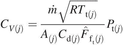
where A(j)Aj is the mechanical flow area at jj.
3. Obtain Vj=Vθj2/1−CVj2
 where Vθ(j) = r(j)Sf(j)ΩVθj=rjSfjΩ.
4. Calculate the static temperature Ts(j)Tsj
Tsj=Ttj−Vj22cp
5. Calculate the Mach number M˜j

M˜j=VjκRTsj
6. Repeat steps from 1 to 5 until M(j)Mj equals M˜j
 within an acceptable tolerance.
7. Calculate the static pressure Ps(j)Psj
Psj=PtjTtjTsjκκ−1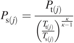


Thus, using the foregoing seven calculation steps, we now have established at section jj all the flow properties: Pt(j)Ptj, Ps(j)Psj, Tt(j)Ttj, Ts(j)Tsj, M(j)Mj, Sf(j)Sfj, Vx(j)Vxj, and Vθ(j)Vθj. Within the cavity control volume, the leakage air flow experiences heat transfer from the cavity stator and rotor surfaces, work transfer (windage) from the cavity rotor surfaces, and the change in its swirl factor as a result of the net torque from the stator and rotor surfaces. For nonzero kinetic energy carry-over factor, the cavity static pressure must be modified to become the total pressure at section j + 1j+1. If r(j)≠r(j + 1)rj≠rj+1, we must also account for the change in static pressure in the forced vortex associated with the seal leakage flow.
Additional calculation steps to obtain Pt(j + 1), Tt(j + 1)Ptj+1,Ttj+1, and Sf(j + 1)Sfj+1 are summarized as follows:
1. Using the methodology presented in Chapter 4, calculate the windage temperature rise ΔTwindageΔTwindage and the swirl factor Sf(j + 1)Sfj+1.
2. From the structural heat transfer analysis of the labyrinth seal, calculate the change in temperature (ΔTHTΔTHT) of the leakage air flow.
3. Calculate the total temperature Tt(j + 1)Ttj+1
Tt(j + 1) = Tt(j) + ΔTwindage + ΔTHTTtj+1=Ttj+ΔTwindage+ΔTHT
4. Calculate the static temperature Ts(j + 1)Tsj+1
Tsj+1=Ttj+1−rj+12Ω2Sfj+122cp−αVxj22cp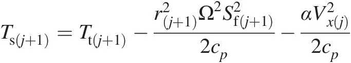
where αα is the kinetic energy carry-over factor given by Equation 5.8.
5. Calculate the static pressure Ps(j + 1)Psj+1
Psj+1=Psj1+κ−12Mθ2rj+12rj2−1κκ−1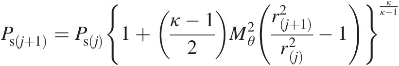
where
Mθ=rjSfj+1ΩκRTsj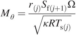
6. Calculate the total pressure Pt(j + 1)Ptj+1
Ptj+1=Psj+1Ttj+1Tsj+1κκ−1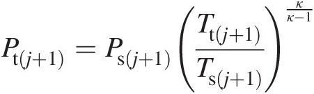


The foregoing six steps to calculate the flow properties at section j + 1j+1 and the previous seven steps for properties at section jj constitute a methodology to march the solution from inlet to outlet of a multitooth labyrinth seal. We iterate this tooth-by-tooth calculation procedure by adjusting the seal leakage mass flow rate ṁ until the computed discharge static pressure for the last tooth equals the specified seal discharge pressure within an acceptable tolerance.
The tooth-by-tooth modeling technique presented here offers significant flexibility to simulate variable seal clearances and other features, including blocker flows if present.
5.3 Concluding Remarks
In this chapter, we have presented comprehensive thermofluids modeling of labyrinth seals, which are ubiquitous in internal flow systems of gas turbines. The tooth-by-tooth modeling combined with the orifice-cavity model presented here will allow a gas turbine designer to handle a general labyrinth seal to accurately compute the leakage mass flow rate, windage temperature rise, and change in flow swirl factor. Considering the labyrinth seal as super-element, this modeling methodology is ideally suited for integration into a 1-D flow network model used for simulating gas turbine internal flow systems. It is important to note that, for the transient operation of a labyrinth seal, one must account for both thermal and centrifugal growth of its structural parts, requiring their multiphysics (mechanical-thermofluids) analysis for which the general methodology is presented in Chapter 6.
For many other static seals such as C-seals, E-seals, W-seals, and spline seals, and dynamic seals such as brush seals, leaf and cloth seals, hybrid brush seals, finger seals, carbon segmented seals, and others, interested readers may find the references and bibliography at the end of this chapter helpful.
Worked Examples
Example 5.1
Consider a two-tooth labyrinth seal whose mean radius under each tooth is rm = 0.5 mrm=0.5m with a clearance of s = 3 mms=3mm. The rotor rotates at 3000 rpm3000rpm, and the swirl factor of the leakage air flow remains constant at Sf = 0.5Sf=0.5. The seal initially operates under the inlet total pressure and total temperature of Ptin = 10 barPtin=10bar and Ttin = 500 KTtin=500K. The outlet static pressure (back pressure) remains constant at Psout = 5 barPsout=5bar. Assume that the kinetic energy carry-over factor is zero, and discharge coefficient Cd = 0.8Cd=0.8. Neglect any change in air total temperature as a result of heat transfer and rotational work transfer (windage).
(a) Compute the leakage air mass flow rate through the seal.
(b) Use a noniterative method to compute the minimum leakage air mass flow rate and inlet total pressure such that the seal just chokes (M2 = 1M2=1) at the second tooth.
Solution
Because the swirl factor remains constant, we may solve this problem in the relative reference frame rotating with the air swirl velocity, using the total pressure and total temperature based only on the axial throughflow velocity. These quantities are computed as follows:
Air tangential velocity:
Vθ=SfrmΩ=0.5×0.5×3000×π30=78.540m/s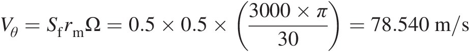
Relative total temperature at the first tooth inlet:
Ttx1=500−78.540×78.5402×1004.5=496.930K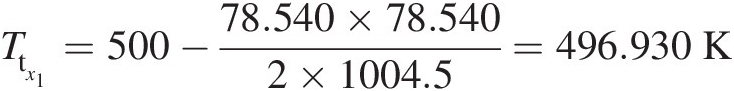
Relative total pressure at the first tooth inlet:
PtinPtx1=TtinTtx1κκ−1=500496.303.5=1.02179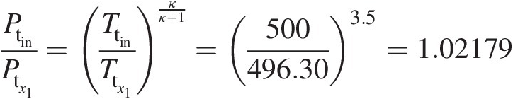
Ptx1=Ptin1.02179=10×1051.02179=9.7867×10⁵Pa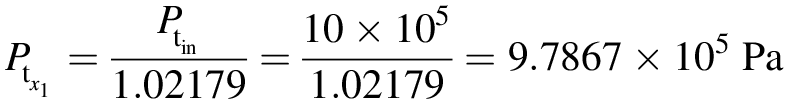


(a) Leakage air mass flow rate through the seal
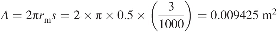
Leakage flow area over each tooth: A=2πrms=2×π×0.5×31000=0.009425m2
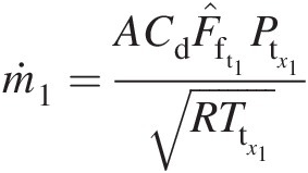
Tooth 1: ṁ1=ACdF̂ft1Ptx1RTtx1
Tooth 2: ṁ2=ACdF̂ft2Ptx2RTtx2=ACdF̂ft2Ps1RTtx1
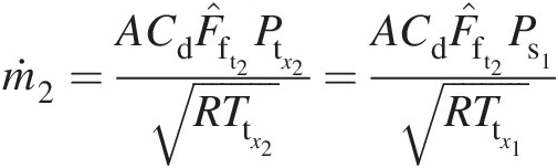
 , Ttx1 = Ttx2Ttx1=Ttx2, and Ptx2 = Ps1Ptx2=Ps1.


The leakage air mass flow rate can be computed using the following iterative method where the converged values are shown within parentheses:

Thus, the seal leakage air mass flow rate computed in this case is 10.657 kg/s10.657kg/s.
(b) A noniterative method to compute ṁ
 and PtinPtin for M2 = 1M2=1 and Psout = 5 barPsout=5bar

When the leakage flow through the labyrinth seal is entirely subsonic, the exit static pressure must be equal to the specified static back pressure. When the last tooth chokes, the exit static pressure could be equal to or higher than the back pressure. In the present case, the inlet total pressure is increased with concurrent increase in the seal leakage air mass flow rate until M2 = 1M2=1, and the exit static pressure equals the specified back pressure of Psout = 5 barPsout=5bar.
To solve for both the mass flow rate and total inlet pressure, we can certainly use an iterative method, similar to the one used in (a). We present here a simple direct solution method, which is based on backward marching from tooth 2 to tooth 1.
Tooth 2:
For M2 = 1M2=1 at tooth 2, we compute the following quantities:
Ps1Psout=κ+12κκ−1=1.23.5=1.8929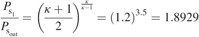
which yields
Ps1=Ps1Psout×Psout=1.8929×5×105=9.4646×10⁵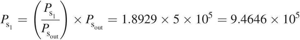
and
F̂fs2=M2κ1+κ−12M22=1.4×1.4+12=1.2961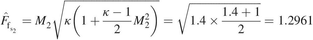


which directly yields the seal air leakage mass flow rate as

and

For directly computing the inlet total pressure at tooth 1, we make use of the following facts:
(1) Static pressure at tooth1 exit equals the total pressure at tooth 2 inlet (α = 0α=0)
(2) For constant total temperature and seal clearance (equal flow area under both tooth 1 and tooth 2), the static-pressure mass flow function of tooth 1 equals the total-pressure mass function of tooth 2.
Therefore, we obtain F̂fs1=F̂ft2=0.6847 , which directly yields M1M1 as

which from isentropic relations gives the total-to-static pressure ratio

and
which finally yields
Therefore, for the choked second tooth, the direct solution method yields the leakage mass flow rate of 12.939 kg/s12.939kg/s at the required inlet total pressure of 1.1977 × 10⁵ Pa1.1977×105Pa. It may be verified that, once the seal is choked, the leakage air mass rate varies linearly with the total inlet pressure while the total-to-static pressure ratio across the seal remains constant. The resulting exit static pressure, therefore, becomes higher than the specified back pressure. This behavior of the choked two-tooth labyrinth seal in this example has significant practical implication. For a given back pressure, we can first compute its leakage mass flow rate and total pressure by using the direct solution method and then scale the values to other inlet and outlet pressure conditions while the seal remains choked.
Example 5.2
For the two-tooth seal of Example 5.1, show that, in order for the leakage air flow to choke under both teeth, the clearance under the second tooth must be increased to satisfy the following relation:

where s1s1 is the seal clearance under tooth 1 and s2s2 under tooth 2.
Solution
From the flow physics of the two-tooth seal of Problem 5.1, we can write Ttx1 = Ttx2Ttx1=Ttx2, Ptx2 = Ps1Ptx2=Ps1, and ṁ1=ṁ2 . We can express the choked mass flow rate under each tooth as follows:


where A1A1 and A2A2 are seal clearances under teeth 1 and 2, respectively, and F̂fs1∗ is the static-pressure mass flow function evaluated at M1 = 1M1=1 and F̂ft2∗
 the total-pressure mass flow function evaluated at M2 = 1M2=1.
Equating ṁ1 and ṁ2
 and simplifying the resulting expression yields

which for air with κ = 1.4κ=1.4 results in the following relation:

Example 5.3
During the air flow testing of a two-tooth labyrinth seal in a nonrotating test rig, the measurements made correspond to Ptin = 122500 PaPtin=122500Pa, Psout = 100000 PaPsout=100000Pa, Ttin = 300 KTtin=300K, and ṁ=0.5680kg/s . The mechanical clearance area under each tooth equals A1 = A2 = 0.005 m2A1=A2=0.005m2. Assuming the leakage flow to be adiabatic with a discharge coefficient Cd = 0.65Cd=0.65 under each tooth, compute the kinetic energy carry-over factor αα from the first tooth exit to the second tooth inlet.
Solution
Because the flow is adiabatic, with no rotational work transfer (windage) in the test rig, the total temperature remains constant from seal inlet to outlet. For the given seal leakage air mass flow rate, we can compute additional flow properties at tooth 1 and tooth 2 as follows:
Tooth 1
From the mass flow rate equation expressed in terms of total-pressure mass flow function, we can write

which yields M1 = 0.3865M1=0.3865 using either an iterative method or table look-up with interpolation.
Static pressure at tooth 1 exit:


Mach number and static-to-total temperature ratio at tooth 1 exit:


Tooth 2
Using equal mass flow rate through each tooth and the given static pressure at tooth 2 exit, we compute the inlet total pressure Pt2Pt2 as follows:


The kinetic energy carry-over factor αα can now be computed as

Project
5.1 Develop a general purpose stand-alone computer code in FORTRAN, or the language of your choice, to solve for swirl distribution, total temperature change as a result of windage and heat transfer, and leakage mass flow rate through a general labyrinth seal. Use the tooth-by-tooth modeling scheme presented in this chapter along with an orifice-cavity model between two adjacent teeth. Include in this compute code the flexibility to input for each cavity a blocker flow and the associated loss in total pressure.
References
Bibliography
Nomenclature
- AA
Mechanical area for seal flow
- CcCc
Seal carry-over coefficient
- CdCd
Discharge coefficient
- CrCr
Seal contraction coefficient
- CtCt
Seal throttling coefficient
- CVCV
Velocity coefficient
- F̂fs

Dimensionless static-pressure mass flow function
- F̂ft

Dimensionless total-pressure mass flow function
- hh
Tooth height
- kk
Carry-over coefficient
- k1k1
Correction factor
- k2k2
Corrected carry-over coefficient
- ṁ

Mass flow rate
- MM
Mach number
- nn
Number of teeth
- pp
Pitch
- PP
Pressure
- rr
Coordinate rr of cylindrical polar coordinate system; radius
- RR
Gas constant
- RsealRseal
Mean radius of a labyrinth seal
- ss
Seal clearance
- SfSf
Swirl factor
- tt
Tooth thickness
- TT
Temperature
- VV
Total velocity
- xx
Cartesian coordinate xx


Subscripts and Superscripts
- (0)0
Upstream of tooth number 11
- HTHT
Heat transfer
- mm
Mean
- (n)n
Downstream of tooth number nn
- ss
Static
- tt
Total (stagnation)
- xx
Axial direction
Greek Symbols
- αα
Kinetic energy carry-over factor
- α˜

Tooth slant angle from vertical
- ββ
Gland factor
- θθ
Tangential direction
- κκ
Ratio of specific heats
- ρρ
Density
- ΩΩ
Angular velocity
