Research and Development Center, Saudi Aramco, Dhahran, Saudi Arabia
71.1 Introduction
Saudi Aramco operates over 16,000 km of carbon steel pipeline for the transportation of hydrocarbon products. Most of these pipelines are buried as they traverse the Saudi Arabian terrain through areas of oversaturated high-salinity sand known as sabkha in Saudi Arabia. The water table depth in sabkha is affected by seasonal and tidal conditions and ranges from the surface to more than a meter below the surface. The close proximity of the water table to the surface in sabkha means that many sections of these pipelines are partially submerged in the high-salinity water at all times. It naturally follows that this hot, high-salinity environment with high oxygen concentration differentials is very corrosive to unprotected carbon steel.
Because of the corrosive environment through which the pipelines traverse, new buried pipelines were first coated externally with a coal tar enamel product. Later, a tape wrap product was used followed by a characteristically higher reliability epoxy coating system in the 1980s. The epoxy coating system is still used today. For additional external corrosion mitigation, cathodic protection is also applied to the coated pipelines.
Unfortunately, the tape wrap and coal tar enamel systems combined with cathodic protection did not provide adequate long-term external corrosion protection, especially in the wetter areas. The tape wrap and coal tar enamel systems often developed areas where the coating became disbonded from the pipeline. Water would often leak and collect under the disbonded areas. Cathodic protection could not penetrate through or follow the same path as the water under the disbonded coating. This weakness of the tape wrap and enamel systems created localized areas of external corrosion on the lines that could not be detected with surface measurements of the cathodic potentials and could not be compensated for with additional cathodic protection current.
The earlier epoxy coating systems also experienced a number of initial failures primarily due to inadequate surface preparation procedures. However, failures in the epoxy systems typically resulted in a measurable cathodic potential reduction, which could be compensated for with additional cathodic protection current.
Since pipeline leaks are clearly not desirable, finding a solution to this problem became imperative. Studies concluded that the most cost-effective solution to address pipeline external and internal corrosion was to carry out the following:
Intelligent instrument scraping is done to locate the areas with external and internal corrosion and to quantify the severity of the corrosion.
The locations with external or internal corrosion rated above a certain level of severity are excavated, and the existing coating is removed.
A prefabricated repair sleeve, normally rolled from plate, is cut to a length that would cover the area of corrosion. These repair sleeves resemble a piece of pipe split horizontally with a bore slightly larger than the outside diameter of the line pipe. Repair sleeves are normally fabricated in 3 m lengths, but they can be cut to cover shorter lengths of corrosion or butt welded together to cover corrosion sites exceeding 3 m in length.
At the repair site, the two pieces are clamped over the exterior of the original pipeline at the location of corrosion.
A repair sleeve is welded together and then carefully welded to the exterior of the original pipeline at each end of the sleeve, creating a short length of double-walled pipeline with a sealed annular space between them.
Once the repair sleeve is completely welded and sealed to the pipeline, the repair sleeve and the adjacent pipeline area are grit-blasted and thoroughly cleaned.
Next, an epoxy coating is field-applied to the exterior of the pipeline and repair sleeve.
The pipeline and repair sleeve are again buried and fall under the influence of the cathodic protection system.
Steps a–h were done on virtually all of the company’s existing scrapeable pipelines to the point where there are over 50,000 repair sleeves. Obviously, the primary purpose of repair sleeves is to prevent leaks from pipelines. Repair sleeves have proven very effective and are still applied today to reinforce areas with external or internal corrosion on a pipeline.
71.1.1 Statement of the Buckle/Collapse Problem
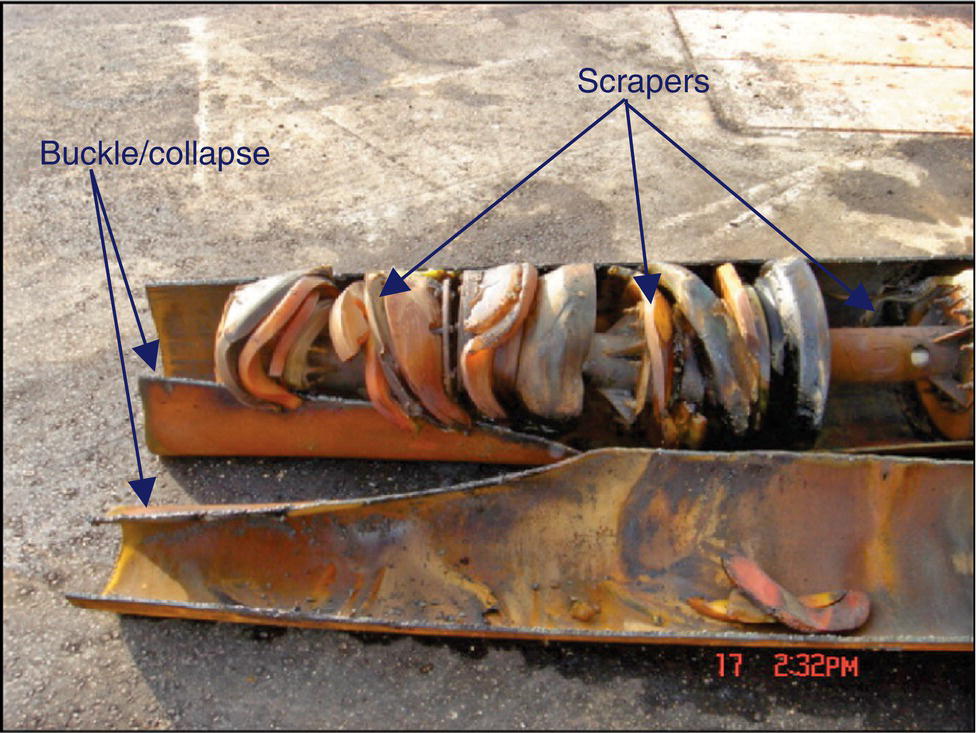
In early 2002, during normal scraping and cleaning operations, a scraper became stuck in a pipeline. Subsequently, a second scraper was sent down the line to free the first, but it too got stuck at the same location. The only solution was to remove that section of pipeline. Figure 71.1 shows an example of these scrapers rammed into a buckle/collapse in the pipeline whereupon they could travel no further. This dent, collapse, or buckle was located directly beneath a repair sleeve. Initial analysis concluded that the inner original pipeline failed by inward collapse, caused by high pressure in the sealed annulus between the repair sleeve and the pipeline. The repair sleeve itself suffered no apparent damage. Unfortunately, this failure recurred frequently with at least 30 similar failures occurring under pipeline repair sleeves within the company. Considering over 50,000 repair sleeves on company pipelines, an understanding of this phenomenon became an important topic.
Figure 71.1 Buckle/collapse along with several stuck scrapers in a 24-in. pipeline. The repair sleeve has already been removed in the photograph.
71.1.2 Observations
It is valuable to summarize the buckle/collapse failures with the following list of general observations.
When installed, the sealed annulus between a repair sleeve and the pipeline contained atmospheric air at ambient pressure.
Post installation of a repair sleeve, the pipeline and repair sleeve are coated externally with epoxy coating.
The pipeline and repair sleeves are predominantly buried, although there are occasional sections above grade.
The pipeline and repair sleeves are cathodically protected.
Sometime after installation, significant elevated pressure develops in the annulus under many repair sleeves.
The elevated pressure is due to high-pressure gas sealed in the annulus.
The high-pressure gas is 100% hydrogen.
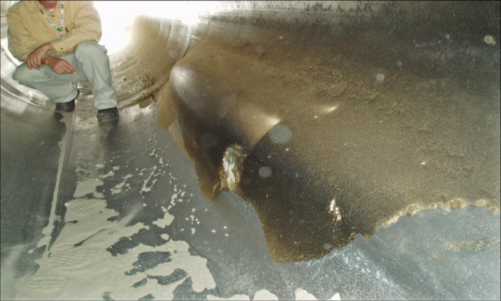
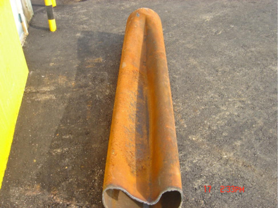
In at least 30 cases, the hydrogen gas pressure was sufficient to cause buckling failure of the pipeline; see Figures 71.2 and 71.3 for examples.
The location of the buckle/collapse on the pipeline is not consistent, but has generally been at the 3 or 9 o’clock position.
The date at which most repair sleeves or the epoxy coating was applied to the pipelines is not known with accuracy. However, a best estimate concludes that the shortest buckle/collapse failure time was approximately 5–7 years after repair sleeve installation.
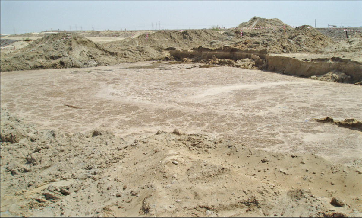
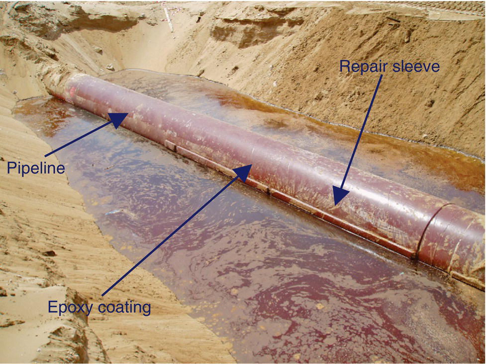
All buckle/collapse failures have occurred in areas of sabkha or high water table and where the pipeline and repair sleeve were at least partially immersed in sabkha water; see Figure 71.4.
Most of the buckle/collapse failures were on pipelines where the internal temperature can reach approximately 60 °C. Nonetheless, one or two failures have occurred on pipelines with ambient internal temperature.
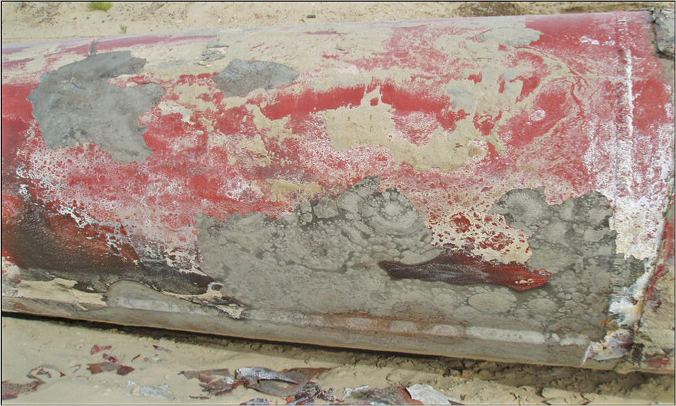
Visual examination indicates that the epoxy coating has been badly damaged at the site of many buckle/collapse failures, while in other cases, it appears visually undamaged; see Figures 71.5 and 71.6.
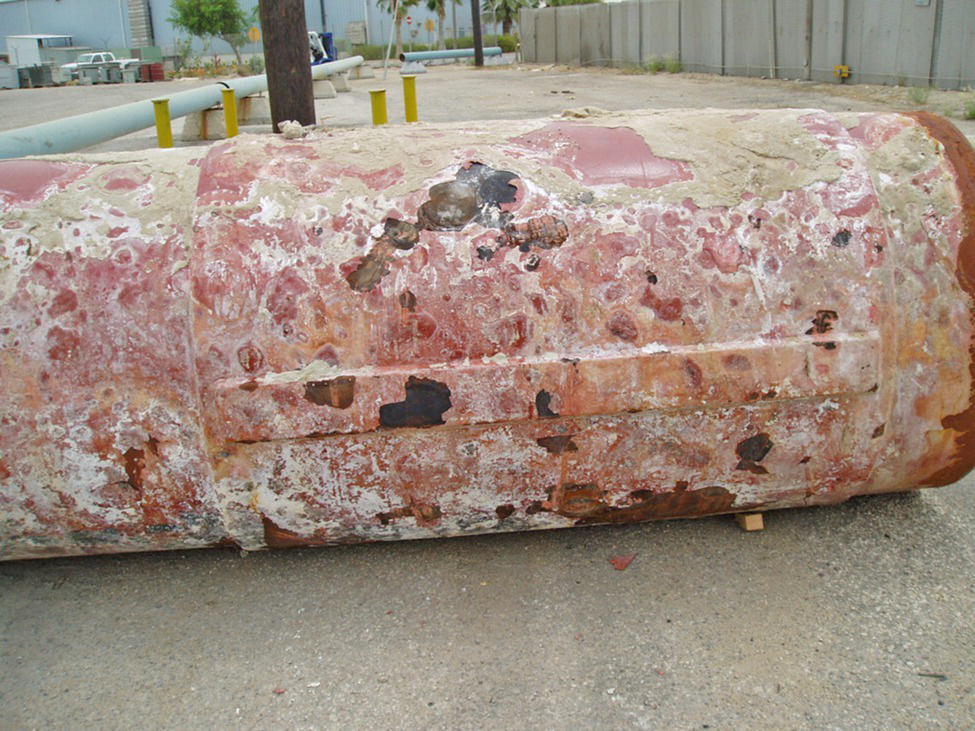
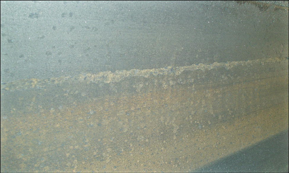
In most failures, scale is present on the exterior of the repair sleeve; see Figure 71.7. A sample of scale collected from this failure site consists of 98% calcium sulfate.
Water was found in the annulus of at least one buckle/collapse failure.
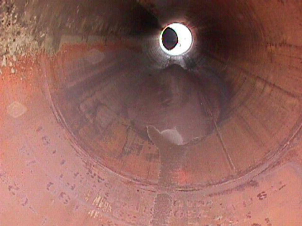
Visual examination of the pipeline interior of most buckle/collapse failures suggests that internal corrosion is not significant; see Figure 71.8. However, at least one buckle/collapse failure did have visible internal corrosion; see Figure 71.9.
No indication of bacterial-related corrosion, biomass, iron sulfide, or odor of hydrogen sulfide gas was found anywhere on the exterior or interior of any buckle failure site.
Hydrogen gas, of insufficient pressure to cause pipeline buckle/collapse, has been found in thousands of annuli under repair sleeves.
Hydrogen gas has been found in the annuli under repair sleeves of several above-grade sections of pipelines.
Figure 71.2 Buckle/collapse failure from inside a 48-in. pipeline.
Figure 71.3 Buckle/collapse failure in an 18-in. pipeline after removal of the repair sleeve.
With this short background, a long-term experimental study of buckling under pipeline repair sleeves was initiated. The objectives of the study were
Figure 71.4 Location of a buckle/collapse failure prior to pumping the sabkha water.
Figure 71.5 Buckle/collapse failure in a 36-in. pipeline where the epoxy coating remains visually undamaged.
To determine the source(s) for hydrogen gas trapped in the annuli of pipeline repair sleeves;
To develop solutions to mitigate buckle/collapse failures under pipeline repair sleeves.
Figure 71.6 Buckle/collapse failure in a 48-in. pipeline where the epoxy coating is badly damaged and scaled.
Figure 71.7 Buckle/collapse failure in a 48-in. pipeline showing bad coating and scale.
Figure 71.8 Interior of a 36-in. pipeline at the location of a buckle/collapse failure showing no visible internal corrosion. Note that the writing from the pipe manufacturer is still visible in the foreground.
Figure 71.9 Photograph of an approximately 18 in. × 36 in. area in the interior of a 48-in. pipeline at the location of a buckle/collapse failure showing visible internal corrosion.
To achieve these goals, a great deal of experimental work was conducted during the course of a 4-year study of the buckle/collapse problem. However, in the interest of brevity, none of the experimental work will be discussed here. What follows are the conclusions that came from the study and answers for the two objectives of the study.
71.2 Study Conclusions
After 4 years of effort, the study team arrived at a number of conclusions related to the buckle/collapse problem. These have been arranged into seven categories and the highlights of each are shown.
71.2.1 Conclusions for Sources of Hydrogen in an Annulus of a Pipeline Repair Sleeve
The amount of hydrogen released from weld metal placed during repair sleeve installation is insignificant with respect to the buckle/collapse failures [1].
Mobile hydrogen from steel manufacturing, which could potentially be released from the repair sleeve steel or the pipeline steel is insignificant with respect to the buckle/collapse failures [2–6].
During repair sleeve installation, native water may be trapped in an annulus.
Carbon steel corrosion within an annulus that contained water would proceed only until the oxygen trapped in the annulus was consumed.
Due to the high pH of native waters, carbon steel corrosion within the annulus could not produce hydrogen.
Any hydrogen produced by direct or indirect microbial activity in an annulus would be insignificant with respect to the buckle/collapse failures [7, 8].
There is no source of hydrogen production within an annulus that would contribute significantly to buckle/collapse failures.
Hydrogen present in above-grade repair sleeve annuli does not come from acid rain corrosion followed by hydrogen permeation through the repair sleeve wall [9].
Hydrogen found in annuli under pipeline repair sleeves comes from pipeline internal corrosion and/or from external cathodic protection.
71.2.2 Factors Affecting Hydrogen Permeation from Inside the Pipeline into an Annulus
It should be assumed that most pipelines, including those considered dry by company operations, do contain sufficient condensed water for some amount of internal corrosion.
Condensed water inside a pipeline must be pH <7 or hydrogen will not be produced as a by-product of the corrosion process. If hydrogen is not produced as a by-product of the corrosion process, then pipeline internal corrosion does not contribute to hydrogen trapped in an annulus.
Both hydrogen sulfide and/or carbon dioxide gases, if present in a pipeline with condensed water, will result in condensed water with a pH <7.
Hydrogen permeation through carbon steel will result from sweet, carbon dioxide, corrosion. Hydrogen sulfide gas is not a prerequisite for hydrogen permeation due to corrosion. Previous work in Saudi Aramco’s laboratories has shown the rate of hydrogen permeation from sweet, carbon dioxide, corrosion to be similar in magnitude to that from excessive cathodic protection.
If hydrogen sulfide is present at concentrations above the low ppm level, then hydrogen permeation resulting from pipeline internal corrosion is significantly higher. Previous work in Saudi Aramco’s laboratories has shown the rate of hydrogen permeation in the presence of hydrogen sulfide to be orders of magnitude greater than that from either excessive cathodic protection or sweet corrosion.
Oxide layers on the outer surface of a pipeline can reduce hydrogen permeation into an annulus from pipeline internal corrosion. However, oxide layers are complex and easily damaged, which make their effect on hydrogen permeation difficult to predict [10–14].
Hydrogen permeation rate decreases with increasing thickness of the steel through which it permeates [15–18].
Hydrogen permeation rate increases with increasing temperature [19].
71.2.3 Factors Affecting Hydrogen Permeation from Outside the Repair Sleeve into an Annulus
The amount of hydrogen present in an annulus, resulting from cathodic protection, is proportional to the current flowing through the repair sleeve. However, the fraction of total hydrogen, resulting from cathodic protection, that permeates into the steel decreases with increasing cathodic protection current density.
Hydrogen permeation rate increases with increasing temperature [19].
Hydrogen permeation rate decreases with increasing thickness of the steel through which it permeates [15–18].
For steels >4 mm thickness, hydrogen permeation resulting from cathodic protection is undetectable at cathodic protection current density levels less than approximately 100 mA/m2.
Oxide layers on the inner surface of a repair sleeve can reduce hydrogen permeation into an annulus resulting from cathodic protection. However, oxide layers are complex and easily damaged, which make their effect on hydrogen permeation difficult to predict [10–14].
Hydrogen permeation resulting from cathodic protection is lower in water that contains high levels of dissolved calcium and magnesium. These ions, in combination with the cathodic protection reduction chemistry, produce carbonate and hydroxide scales that lower hydrogen permeation [20].
Hydrogen permeation resulting from cathodic protection is somewhat higher when the surface of the steel is exposed to degraded epoxy coating [21–23].
71.2.4 Factors Affecting the Rate of Annulus Pressure Increase
Hydrogen permeation through the pipeline wall into an annulus resulting from pipeline internal corrosion is important, and this includes all of the variables discussed earlier.
Hydrogen permeation through the repair sleeve wall into an annulus resulting from cathodic protection is important, and this includes all of the variables discussed earlier [24–34].
The rate of increase of the annulus pressure decreases as the annulus gap increases.
71.2.5 Factors Affecting the Time Required for a Buckle/Collapse Failure
The study concluded that it is not feasible to predict the time required for an individual repair sleeve buckle/collapse failure. The degree of complexity for this failure mechanism is significant, and the time to failure is a function of
The rate of annulus pressure increase is important, and this includes all of the variables discussed earlier.
The pressure required for a buckle/collapse failure decreases with increasing pipeline outside diameter and with increasing repair sleeve length.
The pressure required for a buckle/collapse failure increases with increasing pipeline steel strength and with increasing pipeline wall thickness.
The pressure required for a buckle/collapse failure will be less if the pipeline wall has defects such as general corrosion loss or pitting corrosion. This variable is valid whether the defects are on the internal or external wall of the pipeline.
The pressure required for a buckle/collapse failure is less for a pipeline whose cross section is not circular.
71.2.6 Main Sources and Considerations for Hydrogen Gas Trapped in the Annulus of a Pipeline Repair Sleeve
Recall that this heading is one of the two objectives for the study. The team concluded that there are only two significant sources for hydrogen gas trapped within an annulus of a pipeline repair sleeve, and these are
Excessively high cathodic protection current density results in the production of hydrogen that permeates the repair sleeve wall into the annulus where it is trapped in sufficient quantity to be a primary source of high-pressure gas in the annulus of buckle/collapse failures.
The excessive cathodic protection current density occurs in low-resistivity environments for poorly coated repair sleeves on otherwise well-coated pipelines.
Under the aforementioned conditions, the excessive cathodic protection current density does not create field measurable excessive cathodic protection potentials.
Some condensed water is found in almost all pipeline process environments. Therefore, where condensed water is present in a pipeline process environment, hydrogen produced as a by-product of pipeline internal corrosion will permeate the pipe wall into an annulus where it will be trapped in sufficient quantity to also be a primary source of high-pressure gas in the annulus of buckle/collapse failures. In addition, if hydrogen sulfide is present in the pipeline process environment along with condensed water, then pipeline internal corrosion could become the most significant source of annulus hydrogen and this would produce a situation with high probability of a buckle/collapse failure.
Excessive cathodic protection was identified as a primary source of hydrogen gas trapped in the annuli of pipeline repair sleeves. However, it is essential to understand clearly the following:
Excessive cathodic protection on a pipeline or repair sleeve can occur even if the cathodic protection system has been designed perfectly, is operating perfectly, and is maintained perfectly.
This is because excessive cathodic protection on a pipeline or repair sleeve is the natural and predictable result for any cathodically protected pipeline that has long lengths of pipe with good or high-resistivity external coating connected directly to short lengths of pipe with bad or low-resistivity external coating. In addition, and typical for these cases, an aggravating factor is that the short lengths of pipe with bad coating are usually found in the highest conductivity soils. By itself, this combination can be entirely responsible for excessive cathodic protection because the current generated by the cathodic protection system will naturally focus on the areas of least electrical resistance, which are the areas with bad coating in high conductivity soils. In other words, cathodic protection is a primary source of hydrogen gas trapped in the annuli of pipeline repair sleeves, but bad external coating on the repair sleeve is responsible for creating excessive cathodic protection.
71.2.7 Solutions to Mitigate Buckle/Collapse Failures Under Pipeline Repair Sleeves
Through the course of the study, the team developed both a short-term solution for existing repair sleeves that contain high-pressure gas and two long-term actions that would help mitigate the problem.
Short-term solution: The short-term solution is to vent trapped hydrogen gas from welded repair sleeves using a procedure based on the following steps:
With over 50,000 repair sleeves in the field, a list was prepared that identified locations with higher risk of a buckle/collapse failure. Higher risk locations are sites that have suffered from previous buckle/collapse failures, sites in perennially wet sabkha, and critical pipelines that would create a problem if shut down to repair a buckle/collapse failure.
Once the higher risk sites were identified, excavate the repair sleeves in these locations.
Using a purpose-made remotely operated drill with nitrogen gas purge, carefully, following a specially developed procedure, drill a small hole into the repair sleeve to vent any trapped hydrogen gas therein.
After venting any trapped hydrogen gas, drill the hole larger, tap it, and install a standard National Pipe Thread (NPT) threaded plug fitting as a seal. Hydrogen gas that later permeates into the annulus of a repair sleeve equipped with a threaded plug will leak out around the threads of the plug and never build up sufficient pressure to cause a buckle/collapse. This very simple and low-cost procedure has now been successfully completed on several thousand repair sleeves in the company without incident. In addition, this is a permanent solution for the buckle/collapse problem of the particular repair sleeve.
Be prepared for the event in which pipeline process fluids, rather than hydrogen gas, are found when the small hole is drilled through the repair sleeve wall. In this situation, knock a short length of round steel rod of slightly larger outside diameter (OD) than the drilled hole, but with a tapered tip, into the open hole to block the release of process fluids. This will plug the leak. Next, weld over the plug for a permanent seal. This procedure is a permanent solution for the process fluid leak of the particular repair sleeve. Note in this case that a collapse is impossible due to the open path into the pipeline.
Long-term solutions: The team developed two long-term actions that would help to mitigate future buckle/collapse failures on company pipelines.
For new repair sleeve installations, place a threaded plug in the wall of the repair sleeve when it is being fabricated and prepared. Hydrogen gas that might later permeate into the annulus of the repair sleeve equipped with a threaded plug will leak out around the threads of the plug and never build up sufficient pressure to cause a buckle/collapse. This procedure is a permanent solution for the buckle/collapse problem of the particular repair sleeve.
Coat the pipelines and welded repair sleeves with a better coating: It was clearly pointed out that bad coating on pipeline repair sleeves is the reason for excessive cathodic protection current that ultimately leads to a buckle/collapse failure. Therefore, if the bad coating is replaced with a good coating this will solve the buckle/collapse problem under welded repair sleeves.
71.3 Summary
Poor coating in low-resistivity environments results in excess cathodic protection on pipeline repair sleeves. This, coupled with pipeline internal corrosion, caused high-pressure hydrogen gas trapped in the annulus of repair sleeves to buckle the pipeline under the repair sleeve. A simple remedial solution is to drill the repair sleeve wall, vent the trapped hydrogen, and then fill the hole with a threaded plug.
Acknowledgments
The author would like to thank Saudi Aramco for granting permission to publish this work, including all associated figures.
References
1 Castillo, M., Rogers, C.E., and Payer, J.H. (2000) Hydrogen permeation and hydrogen concentration measurements to model diffusible hydrogen in weld metal. Proceedings of NACE Corrosion 2000, Paper No. 00467.
2 SAE Aerospace (2003) AMS 2759/9B: Hydrogen Embrittlement Relief (Baking) of Steel Parts, April, 2003.
3 ASTM International and Nisbett, E.G. (editor) (2005) Steel Forgings: Design Production, Selection, Testing and Application: (MNL 53), pp. 16 and 126.
4 Randerson, K., Carey, H.C., and Schomberg, K. (2003) A model for calculating solubility of hydrogen in steel. Steel-making, 30(5), 369–378.
5 Sarychev, A.F., Gorostkin, S.V., Sarychev, B.A., and Nikolaev, O.A. (2006) Changing the hydrogen content of alloy steel in relation to the technology used to cool cast slabs. Metallurgist, 50(11–12), 577–580.
6 Zinchenko, S.D., Filatov, M.V., Efimov, S.V., Goshkadera, S.V., and Dub, A.V. (2004) Technological aspects of hydrogen removal with the use of a ladle-type vacuum-degassing unit. Metallurgist, 48(11–12), 553–556.
7 Little, B.J., Ray, R.I., and Pope, R.K. (2000) The relationship between corrosion and the biological sulfur cycle. Proceedings of NACE Corrosion 2000, Paper No. 00394.
8Miyamoto, K. (editor) (1997) Renewable Biological Systems for Alternative Energy Production, Food and Agricultural Organization of the United Nations, Services Bulletin—128.
9 Gordon, J.D., Nilles, M.A., and Schroder, L.J. (1995) USGS Tracks Acid Rain, Fact Sheet FS-183-95, United States Geological Survey, Reston, VA.
10 Casanova, T. and Crousier, J. (1996) The influence of an oxide layer on hydrogen permeation through steel. Corrosion Science, 38, 1535–1544.
11 Chen, R.Y. and Chen, Y.D. (2005) Examination of oxide scales of hot rolled steel products. ISIJ International, 45(1), 52–59.
12 Dey, S., Mandhyan, A.K., Sondhi, S.K., and Chattoraj, I. (2006) Hydrogen entry into pipeline steel under freely corroding conditions in two corroding media. Corrosion Science, 48, 2676–2688.
13 Schmitt, G., Sadlowsky, B., and Noga, J. (2000) Inhibition of hydrogen effusion from steel—an overlooked and underestimated phenomenon. Proceedings of NACE Corrosion 2000, Paper No. 00466.
14 Song, R.H., Pyun, S.I., and Oriani, R.A. (1991) The hydrogen permeation through passivating film on iron by modulation method. Electrochemical Acta, 36, 825.
15 Crolet, J.L. and Bonis, M.R. (2001) Revisiting hydrogen in steel, part I: theoretical aspects of charging, stress cracking and permeation. Proceedings of NACE Corrosion 2001, Paper No. 01067.
16 Crolet, J.L. and Bonis, M.R. (2001) Revisiting hydrogen in steel, part II: experimental verifications. Proceedings of NACE Corrosion 2001, Paper No. 01072.
17 Dean, F.W.H., Carroll, M.J., and Nutty, P.A. (2001) Hydrogen Permeation flux data correlation with in-line corrosion monitoring techniques mapped over location and time. Proceedings of NACE Corrosion 2001, Paper No. 01636.
18 Tems, R.D. and Dean, F.W.H. (2000) Field application of a new, portable, non-intrusive hydrogen monitor for sour service. Proceedings of NACE Corrosion 2000, Paper No. 00471.
19 Addach, H., Bercot, P., Rezrazi, M., and Wery, M. (2005) Hydrogen permeation in iron at different temperatures. Materials Letters, 59, 1347–1351.
20 Ou, K.C. and Wu, J.K. (1997) Effect of calcareous deposits formation on the hydrogen absorption of steel. Materials Chemistry and Physics, 48, 52–55.
21 ASTM Standard Test Method for Arsenic in Paint (2002) ASTM D 2348.
22 Tendulkar, A.N.P. and Radhakrishnan, T.P. (1994) A galvanic study of the role of arsenic on the entry of hydrogen into mild steel. Corrosion Science, 36, 1247–1256.
23 Walker, M. (1999) Arsenic and old paint. New Scientist, 162(2188), 20.
24 Banerjee, K. and Chatterjee, U.K. (2001) Hydrogen permeation and hydrogen content under cathodic charging in HSLA 80 and HSLA 100 steels. Scripta Materialia, 44, 213–216.
25 Benson, J. and Edyvean, R.G.J. (1998) Hydrogen permeation through protected steel in open seawater and marine mud. Corrosion, 54(9), 732–739.
26 Brass, A.M. and Collet-Lacoste, J.R. (1998) On the mechanism of hydrogen permeation in iron in alkaline Medium. Acta Materialia, 46(3), 869–879.
27 Van Delinder, L.S. (editor) (1984) Corrosion Basics, An Introduction, NACE, Houston, TX, p. 120.
28 Flis, J., Zakroczymski, T., Kleshnyal, V., Kobiela, T., and Dus, R. (1999) Changes in hydrogen entry rate and in surface of iron during cathodic polarization in alkaline solutions. Electrochi-mica Acta, 44, 3989–3997.
29 Flis-Kabulska, I., Flis, J., and Zakroczymski, T. (2007) Promotion of hydrogen entry into iron from NaOH solution by iron-oxygen species. Electrochimica Acta, 52, 7158–7165.
30 Flis-Kabulska, I., Zakroczymski, T., and Flis, J. (2007) Accelerated entry of hydrogen into iron from NaOH solutions at low cathodic and low anodic polarizations. Electrochimica Acta, 52, 2966–2977.
31 Hagiwara, N. and Meyer, M. (2000) Evaluating hydrogen stress cracking of line pipe steels under cathodic protection using crack tip opening displacement tests. Proceedings of NACE Corrosion 2000, Paper No. 00380.
32 Song, F.M., Kirk, D.W., Graydon, J.W., and Cormack, D.E. (2003) A new pipeline crevice corrosion model with O2 and CP. Proceedings of NACE Corrosion 2003, Paper No. 03177.
33 Tawns, A. and Oakley, R. (2000) Cathodic protection at a simulated depth of 2500 m. Proceedings of NACE Corrosion 2000, Paper No. 00134.
34 Thomason, W.H. (1988) Quantitative measurement of hydrogen charging rates into steel surfaces exposed to seawater under varying cathodic protection levels. Materials Performance, 27, 633.