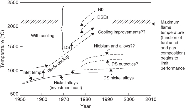
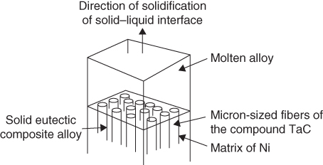
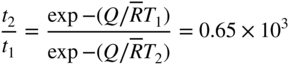
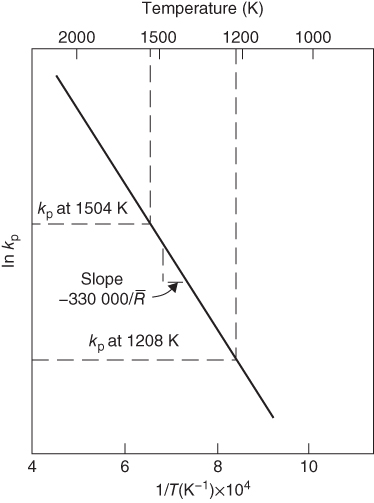
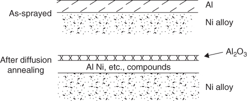
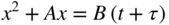
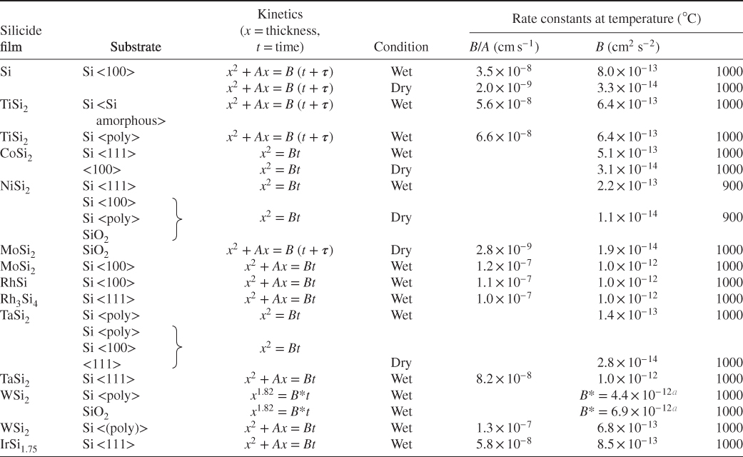
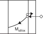
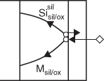
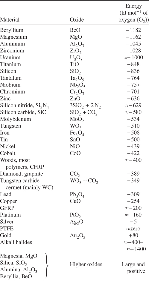
section epub:type=”chapter” role=”doc-chapter”> We hope that the interest in including a chapter on case studies connected with high temperature corrosion in relevant industrial situations and related with theoretical, experimental, or other studies will contribute for the proper analysis and solution of problems with some complexity or difficulty. The case studies presented here have been adapted from recent literature on practical and fundamental problems that have been analyzed and subsequently solved using relatively innovative approaches. The references listed in Further Reading were the main sources for this examination. Mild steel is an excellent structural material, but at low temperature it rusts, and at high it oxidizes rapidly. For many applications, there is a great demand of corrosion‐resistant steel. In response to this demand, a range of stainless irons and steels has been developed. When mild steel is exposed to hot air, it oxidizes quickly to form FeO (or higher oxides). But if one of the elements near the top of Table 20.1 with a large energy of oxidation is dissolved in the steel, then this element oxidizes preferentially (because it is much more stable than FeO), forming a layer of its oxide on the surface. And if this oxide is a protective one, such as Cr2O3, Al2O3, SiO2, or BeO, it stifles further growth and protects the steel. A considerable quantity of this foreign element is needed to give adequate protection. The best is chromium, 18% of which gives a very protective oxide film: it cuts down the rate of attack at 900 °C, for instance, by more than 100 times. Other elements, when dissolved in steel, also cut down the rate of oxidation. Al2O3 and SiO2 both form in preference to FeO (Table 20.1) and form protective films (Table 20.2). Note that 0.7 TM was chosen in Table 20.2 because this is a typical figure for the operating temperature of a turbine blade or similar component. Thus, 5% Al dissolved in steel decreases the oxidation rate by 30 times, and 5% Si by 20 times. The same principle can be used to impart corrosion resistance to other metals. We shall discuss nickel and cobalt in the next case study – they can be alloyed in this way – and so can copper; although it will not dissolve enough chromium to give a good Cr2O3 film, it will dissolve enough aluminum, giving a range of stainless steel called “aluminum bronzes.” Even silver can be prevented from tarnishing (reaction with sulfur) by alloying it with aluminum or silicon, giving protective Al2O3 or SiO2 surface films. And archeologists believe that the Delhi pillar – an ornamental pillar of cast iron that has stood, uncorroded, for some hundreds of years in a particularly humid spot – survived because the iron has some 6% silicon in its composition. Table 20.2 Time, in hours, for material to be oxidized to a depth of 0.1 mm at 0.7 TM in air Data subject to considerable variability due to varying degrees of material purity, prior to surface treatment and presence of atmospheric impurities such as sulfur. TM is the absolute melting point temperature (K). Ceramics themselves are sometimes protected in this way. Silicon carbide, SiC, and silicon nitride, Si3N4, both have large negative energies of oxidation (meaning that they oxidize easily). But when they do, the silicon in them turns to SiO2 that quickly forms a protective skin and prevents further attack. This protection by alloying has one great advantage over protection by a surface coating (such as chromium plating or gold plating): it repairs itself when damaged. If the protective film is scored or abraded, fresh metal is exposed, and the chromium (or aluminum or silicon) it contains immediately oxidizes, healing the break in the film. The development of turbine blade materials to meet the challenge of increasing engine temperatures must satisfy the requirements listed in Table 20.3. Table 20.3 Alloy requirements These requirements severely limit our choice of very resistant materials. For example, ceramics, with their high softening temperatures and low densities, are ruled out for aeroengines because they are far too brittle (they are under evaluation for use in land‐based turbines, where the risks and consequences of sudden failure are less severe). Cermets offer no great advantage because their metallic matrices soften at a too much low temperature. The materials that best fill present needs are the nickel‐based superalloys. The alloy used for turbine blades in the high pressure stage of an aircraft turbofan engine is a classic example of a material designed to be resistant to dislocation (power‐law) creep at high stresses and temperatures. At takeoff, the blade is subjected to stresses approaching 250 MN m−2, and the design specification requires that this stress be supported for 30 hours at 850 °C without more than 0.1% irreversible creep strain. In order to meet these stringent requirements, an alloy based on nickel has evolved with the rather mind‐boggling specification given in Table 20.4. The point of all these complicated additions of foreign atoms to the nickel is straightforward. It is (i) to have as many atoms in solid solution as possible (the cobalt, the tungsten, and the chromium); (ii) to form stable, hard precipitates of compounds like Ni3Al, Ni3Ti, MoC, and TaC to obstruct the dislocations; and (iii) to form a protective surface oxide film of Cr2O3 to protect the blade itself from attack by oxygen. These superalloys resist creep so well that they can be used at 850 °C, and they are so hard that cannot be machined easily by normal methods and must be precision‐cast (for example, by investment casting that produces a fine‐grained material that may undergo a fair amount of diffusion creep and that may fail rather soon by cavity formation) to their final shape. Due to this, the blades are expensive, the total cost of a rotor of 102 blades being €200 000. To stave off failure, the alloys are directionally solidified (DS) to give long grains with grain boundaries parallel to the applied stress. DS alloys are standard in high performance engines and are now also in use in civil aircrafts. The improved creep properties of the DS alloy will allow the engine to run at a flame temperature approximately 50 °C higher than before, for a doubling in production cost. Figure 20.1 shows how this evolutionary process has resulted in a continual improvement of creep properties of nickel alloys over time and shows how the amounts of the major foreign elements have been juggled to obtain these improvements – keeping a watchful eye on the remaining necessary properties. The figure also shows how improvements in alloy manufacture – in this case the use of directional solidification – have helped to increase the operating temperature. Nevertheless, it is clear from the graph that improvements in nickel alloys are now nearing the point of diminishing returns. Table 20.4 Composition of typical creep‐resistance blade Figure 20.1 Superalloy developments by a sort of creepy Darwinism. Internal cooling of the blade enabled the inlet temperature of the turbine to be increased immediately by 100 °C with no change in alloy composition. Later, film cooling constituted a continuous improvement in turbine blades (Figure 20.2). But by further ducting cold air through the blades will begin to reduce the thermal efficiency, and thus a unique characteristic of some alloys, called eutectics, was explored. These eutectics form spontaneously on aligned reinforced structure, which is usually a compound with high melting temperature, whose fibers improve the creep properties of the resulting composite alloy. Figure 20.2 Temperature evolution and future materials trends in turbine blades. Figure 20.3 shows how eutectics are made, and Table 20.5 lists some typical high temperature composites under study for turbine blade applications. Figure 20.3 Directionally solidified eutectics for turbine blades. Table 20.5 High temperature composites As shown in Figure 20.2, if directionally solidified eutectics (DSEs) prove successful, they will allow the metal temperature to be increased by ≈100 °C above conventional DS nickel alloys and the inlet temperature by ≈200 °C (because of a temperature scaling effect caused by the blade cooling). Further improvements in alloy design are underway in which existing nickel alloys and DSEs are being blended to give a fiber‐reinforced structure with precipitates in the matrix. The ceramics best suited for structural use at high temperatures (≥1000 °C) are listed in Table 20.6 and compared with nickel‐based superalloys. The comparison shows that all the ceramics have attractively low densities, high moduli, and high melting points (and thus excellent creep strength at 1000 °C); and many are completely resistant to oxidation – they are oxides already. But several have poor thermal conductivity (leading to high thermal stresses), and all have very low toughness. Table 20.6 Ceramics for high temperature structures To overcome their major problems, ceramic matrix components are under development: they combine strong, exceptionally perfect, fibers (such as silicon carbide or alumina, grown by special techniques) in a matrix of ceramics (silicon carbide or alumina again), made by conventional means to give a material that you might think of as “high temperature wood.” Any major materials development program, such as that on the DSEs, can only be undertaken if a successful outcome would be cost effective. The cost of the materials themselves must also be considered. For example, the use of greater quantities of exotic materials, such as hafnium, will drive the cost of blades up. But if new alloys offer improved life or inlet temperature, there is a strong incentive to pursue them. As we saw above, the alloys used for turbine blades contain large amounts of chromium, dissolved in solid solution in the nickel matrix. Now, if we look at Table 20.1, we see that the formation of Cr2O3 releases much more energy (701 kJ mol−1 of O2) than NiO (439 kJ mol−1 of O2). This means that Cr2O3 will form in preference to NiO on the surface of the alloy. Obviously, the more Cr in the alloy, the greater the preference for Cr2O3. At the 20% level, enough Cr2O3 forms on the surface of the turbine blade to make the material act a bit as if it were chromium. Suppose for one moment that our material is chromium. Table 20.2 shows that Cr would lose 0.1 mm in 1600 hours at 0.7 TM. Of course, we have forgotten one thing, 0.7 TM for Cr is 1504 K (1231 °C), whereas, as already mentioned, for Ni it is 1208 K (935 °C). We should, therefore, consider how Cr2O3 would act as a barrier to oxidation at 1208 K rather than at 1504 K (Figure 20.4). The oxidation of Cr follows parabolic kinetics with an activation energy of 330 kJ mol−1. Then the ratio of the times required to remove 0.1 mm (from equation Figure 20.4 Kp variation with temperature. Thus, the time at 1208 K is t2 = 0.65 × 1.6 × 106 hours = 1.04 × 10⁶ hours. Note that in Eq. 20.1, t1 and t2 are the oxidation times with t2 > t1. Now, as we have said, there is only at most 20% Cr in the alloy, and the alloy behaves only partly as if it were protected by Cr2O3. In fact, experimentally, we find that 20% Cr increases the time for a given metal loss by only about 10 times, i.e. the time taken to lose 0.1 mm at blade working temperature becomes 600 × 10 hours = 6000 hours rather than 106 hours. Why this large difference? Well, whenever you consider an alloy rather than a pure material, the oxide layer – whatever its nature (NiO, Cr2O3, etc.) – has foreign elements contained in it, too. Some of these will greatly increase either the diffusion coefficients in, or electrical conductivity of, the layer and make the rate of oxidation through the layer much more than it would be in the absence of foreign elements contamination. This 0.1 mm loss in 6000 hours from a 20% Cr alloy at 950 °C, though better than pure nickel, is still not good enough. The obvious way out of this problem is to coat the blades with a protective layer (Figure 20.5). This is usually carried out by spraying molten droplets of aluminum onto the blade surface to form a layer, some microns thick. The blade is then heated in a furnace to allow the Al to diffuse into the surface of the Ni. During this process, some of the Al forms compounds such as AlNi with the nickel – which are themselves good barriers to oxidation of the Ni – while the rest of the Al becomes oxidized up to give Al2O3. Figure 20.5 Protection of turbine blades by sprayed‐on aluminum. Because oxides are usually quite brittle at the temperatures encountered on a turbine blade surface, they can crack, especially when the temperature of the blade changes and differential thermal contraction and expansion stresses are set up between alloy and oxide. These can act as ideal nucleation centers for thermal fatigue cracks, and because oxide layers in nickel alloys are well stuck to the underlying alloy (they would be useless if they were not), the crack can spread into the alloy itself. The properties of the oxide film are thus very important in affecting the fatigue properties of the whole component. The pure refractory metals Nb, Ta, Mo, and W have high melting temperatures (2740, 3250, 2880, and 3680 K, respectively) and should therefore have very good creep properties. But they oxidize very rapidly indeed (see Table 20.2) and are utterly useless without coatings. The problem with coated refractory metals is that if a break occurs in the coating (e.g. by thermal fatigue, erosion by dust particles, etc.), catastrophic oxidation of the underlying metal will take place, leading to rapid failure. The “unsafeness” of this situation is a major problem that has to be solved before we can use these on‐other‐counts potentially excellent materials. The ceramics SiC and Si3N4 do not share this problem. They oxidize readily (Table 20.1); but, in doing so, a surface film of SiO2 forms that gives adequate protection up to 1300 °C. And because the film forms by oxidation of the material itself, it is self‐healing. Electronic materials are those used in electrical industries, electronics and microelectronics, and the substances for the building up of integrated circuits (ICs), circuit boards, packaging materials, communication cables, optical fibers, displays, and various controlling and monitoring devices. Discovery, development, and application of new materials are the robust power for the development of human society. Processing of electronic materials mainly includes crystal growth, epitaxy, lithography, deposition, annealing, doping (diffusion or ion implantation), etching (dry or wet), and metallization. In ICs, the fundamental electronic switching device is the (complementary) metal oxide semiconductor field effect transistor (MOSFET), which has at least three terminals – the gate, source, and drain. The gate electrode is separated electronically from the source and drain by a thin dielectric film, which is commonly SiO2. Formation of this film could be accomplished by using sputtering, evaporation, chemical vapor deposition, or atomic layer deposition. Thermal oxidation is also used to grow the gate dielectric films due to its ease in processing control, but it results in many problems in association with material degradation at high temperature; these problems lead to the formation of oxides, carbides, sulfides, nitrides, etc., but when these oxidation processes are well controlled, they have been finding many applications in the modern electronics industry for surface cleaning, film growth, preparation of new materials, and building up of novel structures for devices. To date, Si is still the backbone of the modern semiconductor industry due to its (i) availability in a wide variety of sizes and shapes, (ii) mature material preparation and property control, (iii) native oxide films on its surface, and (iv) compatibility to planar IC technology. Silicides of transition metals are used in two distinct ways in very large scale integrated (VLSI) circuits: (i) in the contact pads of individual devices on a chip and (ii) in the interconnection lines. For the latter applications, two particular properties of the silicides make them desirable: their metallic electrical conductivity and the possibility to produce a protective coating of SiO2 under heat treatment in an oxidizing ambient. Of those two attributes, the second one is particularly attractive because it offers inherent advantages in multilevel metallization schemes. To use this feature of silicides successfully, an understanding of the oxidation process is needed. It is convenient to subdivide the subject into two parts, depending on whether the silicide rests on a substrate of excess silicon or whether the substrate is inert, that is, the substrate is in a fully oxidized state, such as SiO2. Other reasons for the use of silicides in VLSI applications are their very low resistance; good process compatibility with Si, e.g. ability to withstand high temperatures; oxidizing ambients; various chemical cleans used during processing; little or no electronization; easy to dry etch; and good contacts to other materials. But these benefits rise many problems in integrating silicides in an IC, and under this point of view, the actual preferred silicides are WSi2, TiSi2, NiSi, and CoSi2. Table 20.7 indicates preferred silicides for VLSI application. The main techniques used for the formation of these silicides are (i) metal deposition on Si and formation by thermal heating, laser irradiation, or ion beam mixing (these are sensitive to interface cleanliness and heavy doping, selective silicidation on Si possible, and widely used for silicides of Pt, Pd, Co, and Ti), (ii) co‐evaporation (E‐gun) of metal and Si (poor process control, poor step coverage, and good tool for research but not used in manufacturing), and (iii) sputtering from a composite target (possibility of high level of contaminants like C, O, Na, and Ar; poor step coverage; used for MoSi2 and WSi2). Table 20.7 Overall properties of preferred silicides for VLSI applications Typically, silicides are not used alone as interconnections, but with an underlayer of polycrystalline Si. Upon thermal treatment in an oxidizing ambient, most silicides form a SiO2 overcoat while the silicide layer below is morphologically preserved. The rate of growth of the SiO2 layer is different for the different silicides, and these rates also differ from that of pure Si. They can be represented by the linear–parabolic growth law where x is the oxide thickness, t the oxidation time, B the parabolic rate constant, B/A the linear rate constant, and τ a fitting parameter that takes into account the initial transient oxide growth. Table 20.8 lists the growth kinetics of silicides. There are some discrepancies between different studies of the same silicides, but the overall differences between various silicides cannot be explained by details of the silicide preparation method. What then is the origin of these differences? An analysis of the results leads to the following observations: When the metal moves, it must be supplied from the dissociation of the silicide at the silicide/SiO2 interface as a result of the oxidation process. At the elevated temperatures of oxidation, the metal transport process is quite fast, as it is known from silicide formation reactions with metal films, whose rates are similar at lower temperatures. If the dissociation process at the silicide/SiO2 interface is very effective, the oxidation process will be controlled only by the oxygen arrival at the interface, and the linear term in the growth equation should be negligible. Experiments indeed confirm this scenario for CoSi2 and PdSi. When the dissociation process is so effective that it produces an excess of weakly bonded metal and Si at the interface, the possibility of an additional transport of Si down to the substrate, in parallel to the transport of metal, also arises. In this case, both atomic species participate in the mass transport. This situation has been identified for CrSi2, NiSi2, and PdSi. Note that the cases of CoSi2 and PtSi differ from these three cases only quantitatively in that the Si transport may be too small to be measured for CoSi2 and PdSi. Qualitatively, these five silicides are all similar. One would expect that these conditions of ready dissociation and rapid mass transport through the silicides favor the highest possible oxidizing rates. Indeed, the silicides that dissociate during oxidation (CoSi2, NiSi2, PdSi, PtSi) have the highest oxidation rates. Note that the lowest eutectic temperature in the Pt–Si system is 830 °C; oxidation studies performed at 750 °C yield a combined linear and quadratic growth law. From the point of view of low temperature processing, the near‐noble metal silicides are thus preferred candidates for IC interconnections. These results are summarized in Table 20.10. It is seen that there are two additional transport cases that are conceivable when both species move and the silicide layer is preserved during oxidation. These cases have not been seen experimentally. The second limiting case is represented by TiSi2. Silicon is the main diffusion species there. The transport of Si across TiSi2 is one of a few cases where the diffusion mechanisms have been identified for the silicide formation by reaction with a Ti film using radioactive tracers. The Si diffuses from the substrate by a process that involves the atoms in the silicide lattice (e.g. by Si vacancies). In this case, dissociation of the silicide needs to occur. In the initial phase of the oxidation, where the supply of oxygen is high because the oxide layer is thin, the reaction at the silicide/SiO2 interface reduces the overall rate of oxidation, and the linear rate constant B/A begins to be important as well. As a result, the growth is slowed down initially as compared with the previous limiting case. There are uncertainties in the reported values of the linear rate constant for different silicides, because the measurements are difficult to be done accurately. It is nonetheless clear that for both wet and dry oxidation, the linear rate constant is higher for silicides than it is for silicon. The observation can be linked to the metallic properties of the silicides. An electron transfer process in one or several of the steps of the oxidation reaction at the interface can readily alter and accelerate the reaction. That electron transfer process is more probable when the surface is metallic than when semiconducting. Support for this idea is provided by the wet oxidation of Ir3Si5. This silicide is known to be a semiconductor. Its linear rate constant is indeed larger than that of silicon but smaller than that of the metallic silicides. The actual processes that determine the value of the linear rate constant for oxidation of different silicides on silicon remain to be established. This subject is one of the main open issues of silicide oxidation that awaits clarification. Table 20.8 Kinetics of SiO2 growth by thermal annealing of silicide films on various substrates in oxidizing ambient Units of B* are in centimeters and seconds with appropriate powers. Source: Adapted from Bartur and Nicolet (1984). Table 20.9 Dominant diffusion species during silicide formation and oxidation Source: Adapted from Bartur (1983). Table 20.10 The different possible movements for mass transport during silicide oxidation Source: Adapted from Bartur (1983). These considerations suggest that silicides in which the metal is the dominant moving species offer an advantage over the others when low temperature oxidation is desired, but other considerations, such as the diffusion of metal atoms from the silicide into the Si substrate or the electrical resistivity of the silicides, are important in practical applications as well. When the substrate cannot be oxidized, as in the case of SiO2, the metal to silicon ratio increases as the oxidation proceeds. In those cases that have been most studied (NiSi2 and CoSi2), the system evolves slowly enough that thermal equilibrium prevails. The ternary phase diagram then will predict if and when the metal will begin to oxidize, even when this does not occur in the presence of excess silicon. When a tieline connects a particular silicide to a metal oxide, the pure metal and SiO cannot coexist at thermal equilibrium. In such a case, a metal oxide begins to form when sufficient silicon has been extracted from the silicide layer into the SiO2 to increase the metal to silicon ratio to that of the particular silicide. Titanium and tantalum are examples of this type. When TiSi2 is transformed beyond Ti5Si3, titanium oxides begin to form. On the other hand, if a tieline connects the metal to SiO2, it becomes possible to reduce the silicide film to an elemental metal. It has been proposed that metallic interconnection lines could be formed in this manner, in a way that would be quite compatible with existing polycide technology. Two difficulties need to be overcome to carry out such a scheme with NiSi2 or CoSi2. Firstly, silicon must be extracted from the metal to levels below 1 at.% (less than 10% of the solid solubility limit); otherwise the electrical resistivity of the metal approaches or even exceeds that of the original silicide. Secondly, the metal film tends to break up into islands, which can interrupt the electrical continuity of a line. It remains to be established if these difficulties are general to all metals that can coexist in equilibrium with SiO2. Several reviews discussing silicides, their properties, and their application to VLSI technology contain sections on oxidation of silicides (see Further Reading). New technologies and processes that are being applied in the petrochemical industry are requiring higher operating temperatures and pressures of the process units. Therefore, catastrophic consequences such as firing and/or explosion might be caused by the failures initiated by severe corrosion and oxidation attacks of the materials. The major high temperature corrosion attacks in the petrochemical industry include high temperature oxidation, high temperature sulfidation, high temperature naphthenic acid corrosion, and high temperature carburization. Extensive studies and tests on these problems at a laboratory scale have been reported, but the acquired knowledge is not sufficient to guide field corrosion protection practice. Thus the rational selection of materials for the construction of processing units based on the analyses of the nature of the materials and their actual operating conditions is the key to controlling high temperature corrosion. Oxidation, sulfidation, and carburization are three types of phenomena that are treated in Chapters 7–9 of this book. Here, we will only consider two case studies of naphthenic acid corrosion. Naphthenic acid in crude oils is a rather complex mixture, with a saturated ring structure and a molecular weight ranging from 180 to 700. Its content is usually expressed by the total acid number (TAN; as milligrams of KOH required to neutralize the acid in 1 g of oil). During the refining processes, naphthenic acid is heated, distilled, vaporized, and condensed. Then it can dissolve into the distillate oil, resulting in corrosion problems. Particularly at temperatures higher than 240 °C, serious corrosion reactions take place: Iron naphthenate, the product of naphthenic acid corrosion, is oleo‐soluble; therefore, the corroded metal surfaces are normally clean and free of scales. In the regions with high temperature and high flow velocity, naphthenic acid corrosion will result in the formation of shape‐edged streamline grooves along the flow direction. In the areas with low flow velocity, shape‐edged pits will be formed. Since Fe(COO)2 can dissolve into oils and then be removed easily by the flowing media, it is difficult to form protective scales on the metal surface. Even FeS formed on the surfaces can react with naphthenic acid: fresh metallic surfaces will be exposed to the corrosive media, and corrosion can proceed continuously. TANs of the crude oil and the distillate oil are the key factor to evaluate high temperature naphthenic acid corrosion. It is generally accepted that when the TAN is higher than 0.5 mg KOH g−1, high temperature naphthenic acid corrosion will occur. Since naphthenic acid exists together with other oils that have similar boiling points, only the actual acid number of the distillate oils can determine the corrosivity and the corrosion rate. Under atmospheric distillation conditions, the highest acid number of the distillate oil will be shown in the temperature range of 371–426 °C and at 260 °C in vacuum distillation towers. Two case studies in high temperature naphthenic acid corrosion that deserve description are those with high TAN and low sulfur and those with high TAN and high sulfur. In the atmospheric and vacuum units of a refinery, in which heavy crude oils with sulfur lower than 0.5% and TAN of about 3.0 mg KOH g−1 were processed, severe corrosion was observed. Localized corrosion, consisting of a lot of pits, was formed on the inner wall of the tower wall on the third floor, manufactured by using carbon steel and 316L stainless steel. Collapse of the packing materials (316L SS) of the fourth floor led to a high hole, and the oil collection tank on the third floor was also corroded. Failure analysis showed that (i) the TAN of the vacuum distillate oil might be quite high resulting in an increase of the concentration of the corrosive medium and then an increase of naphthenic acid corrosion rate, (ii) FeS scales cannot be formed on the metal surfaces since the sulfur content is low, (iii) the vacuum distillation system is in the state of negative pressure operation, and (iv) the electric desalting and alkali injecting process might not work very well, being unable to decrease the concentration of the corrosive medium in the oil to a low level to decrease the corrosion rate. To control the corrosion, it was suggested to change the packing materials of the third/fourth floors and the oil collection tank, and the desalting/injection processes should be improved to decrease the content of the corrosive media in the oils to inhibit the corrosion process. The average TAN of another refinery was 1.0 mg KOH g−1, the sulfur content was 0.8%, and the density was 0.9 g cm−3. The packing/component materials were 304 SS. Collapse of the packing materials on the second floor due to corrosion was observed, as well as holes on the bottom of the oil collection plates. Most packing material on the fourth floor was corroded. Failure analysis showed that since 304L has a relatively low resistance to these corrosion processes, severe attack occurred. In addition, higher loads in the vacuum distillation system and very high velocity of the processing media contributed to the severe corrosion. It was suggested that all the packing materials should be upgraded to 316L SS; moreover, the oil collection tank should be changed, and the load and velocity of flow should also be decreased. As illustrated by these two case studies, corrosion by naphthenic acids is a complicated process, and the research studies published in the open literature are not enough to explain the corrosive behaviors. Although it was found that the presence of naphthenic acids would lead to the formation of a protective iron oxide or magnetite layer, more questions relating to this issue arise and need further investigation: Apart from this kind of recommendations for future work on this issue, techniques to control high temperature naphthenic acid corrosion must be developed and rapidly implemented. For example, during operation the corrosion rate of the equipment should be monitored regularly to ensure that the processing units can run safely; high velocity of flow and occurrence of turbulence should be avoided in engineering design and practical operation; the TAN of crude oils can be decreased through suitable mixing processes, i.e. addition of crude oils with a low TAN into crude oils with a high TAN may obtain a mixed crude oil with a low TAN, which partly solves the naphthenic corrosion. Surface modification is also one of the effective ways to improve the resistance of carbon steels against high temperature naphthenic acid corrosion. Therefore, some components in the vacuum distillation towers can be built by using carbon steels with suitable aluminizing treatments. Currently, Mo‐containing 316 SS and 317 SS (>2.5% Mo) are the best materials against high temperature naphthenic acid corrosion. However, in the regions with high‐speed flowing media or strong impacts, even 316 SS will suffer severe attack. The class of monolithic and composite ceramic materials termed engineering, technical, or advanced ceramics exhibits an attractive range of properties relative to metallic counterparts commonly used in a number of high temperature applications. In particular, retention of mechanical properties to temperatures in excess of 1200 °C presents the opportunity to plant designers to increase operating temperatures, improve process efficiencies, and reduce the levels of emitted pollutants. Lower densities of ceramic materials than competing metallic counterparts permit the achievement of higher specific strength and thus increased pay loads and reduced energy consumption. Advanced ceramics are thus attractive candidate structural materials for use in energy production and conversion and in engines. Continued progress to actual adoption in commercial installations has been hindered mainly by poor mechanical reliability and uncompetitive production costs. Advances in manufacturing technology are yielding improvements in mechanical performance and gradually reducing the cost of production. While the financial systems for determining cost are well developed and understood, the judgment of component reliability is dependent on the availability of a solid base of valid materials test data. Independently of these issues, it is a fact that structural ceramics are finding more and more applications in high temperature systems, as shown in Table 20.11, and therefore oxidation and corrosion at high temperatures becomes an important field of study. Ceramics can be classified according to the type of protective oxide they form. These include silica formers (SiC, Si3N4), alumina‐forming non‐oxides (AlN, Al4C3), and boria‐forming ceramics (BN). Next, transition metal carbides and nitrides that form the corresponding transition metal oxides, as well as the ceramics that form the mixed oxide scales, are also deserving attention. Finally, the oxidation of ceramic matrix composites (CMCs), which involves several parallel processes, is an important current area of research. These CMCs are the most promising ceramics today for high temperature structural applications. They include whiskers, particulates, and continuous fillers in a ceramic matrix to impart improved fracture toughness. Most of the current research on CMCs is focused on SiC inert fiber coatings in matrices of oxides, Si3N4, or SiC. The most adequate coatings are graphite carbon and boron nitride. Thus, the entire composite has a slowly oxidizing phase (fibers and matrix) and an easily oxidizable phase (fiber coating). Generally, at high temperatures, SiO2 rapidly forms on the outside of the matrix, and attack of the fiber coating is minimized. Even a matrix crack may quickly seal. However, at intermediate (500–1000 °C) temperatures, silica forms very slowly, and oxidative attack of the fiber coating becomes a critical issue. The most thorough treatment of this problem is from Filipuzzini (1994) for carbon‐coated SiC fibers in a SiC matrix. The initial treatment consisted of a matrix with unidirectional fibers with one end exposed. The process consisted on a two‐step oxidation of carbon and concurrent oxidation of the fiber and surrounding matrix. As carbon oxidizes, an annular region around the fiber is left. Filipuzzini first measured oxidation properties of each of the constituent parts of the composite as well as the composite as a whole. Standard thermo‐gravimetric analysis (TGA) methods and resistivity measurements gave an indication of the amount of carbon consumed. These data were used in an overall description of the composite oxidation. By introducing analytical models with appropriate boundary conditions, it was possible to generate TGA oxidation curves, indicating that thinner carbon coatings give better performance. This analysis has been extended to other situations. For example, the examination of the oxidation of SiC matrices with carbon fibers indicated that the low temperature oxidation is kinetically controlled by reaction of oxygen with the fibers and high temperature oxidation is diffusion controlled by diffusion of oxygen to the fibers. Finite difference models of this process were developed. Table 20.11 Current uses of ceramics The other commonly used fiber coating is hexagonal BN. There are several important phenomena in the oxidation of a silicon‐based composite with BN fiber coatings. As the silicon‐based material and the BN oxidize, both B2O3 and the SiO2 form. These react to form low‐melting borosilicate melts. Related to this, boron enhances the oxidation of silica‐forming materials. Also, water vapor readily reacts with B2O3 oxidation product and forms volatile HxByOz (g) species, which leads to effective volatilization of BN. However, unlike carbon volatilization, distinct interfaces are not formed with the BN. Rather there is a “plug” of borosilicate formed and a gradual transition from oxide to nitride. Jacobson, in 1999, described a model that explains the formation of this borosilicate plug, based on gas‐phase diffusion of the HxByOz (g) species outward and boron‐enhanced oxidation of the SiC. Exposures of the SiC fiber to BN fiber coatings in a SiC matrix were conducted at 700 and 800 °C in 1 and 10% H2O/O2 atmospheres with one end of the test sample ground off to expose the fiber ends and coatings. Then recession distances were measured, but exact distances were difficult to determine as interfaces were not always sharp. Therefore, an adjustable parameter of boron‐influenced SiC oxidation rates had to be introduced. Using substantially enhanced oxidation rates, reasonable agreement between the model and experimentally measured recession distances was obtained. Nowadays, the oxidation of CMCs continues to be a major issue because these ceramics are finding novel applications and are being exposed to more complex corrosive environments. The subject of reinforcement corrosion is widely described in the open literature, but descriptions of corrosion that occurred in dry‐process, rotary, cement‐clinker kilns and other structures producing cement seldom appear in literature. Here we describe observed corrosion of kiln shells reported by Potgieter, in 2004, which occurred at two rotary cement kilns, in South Africa. A rotary cement kiln can be seen as a complex chemical reactor with various temperature zones and differing container wall constituents in the different temperature zones. Further on, the number of preheaters, raw material composition, and operating conditions can all influence the corrosion occurring in a rotary cement kiln. The chemical composition of the raw material used and type of refractory used are the main variables contributing to corrosion. Chlorine, sulfur, and alkalis are usually present in the kiln, leading to the production of low‐melting eutectics that, in combination with the oxidizing atmosphere that exists in the kiln, are aggravating factors that can further salt infiltration into the refractory and ultimately hasten corrosion that occurs on the kiln shell. In practice, the observed corrosion processes are similar to those occurring in steam boiler walls that are covered with deposits; thus the kiln acts as a wall deposit. The iron from the steel shell, in contact with the oxidizing atmosphere, originates several iron oxides (Fe3O4 in particular) with hematite (Fe2O3) at the scale–brick interface. Sulfur from the fuel can react in the oxidizing atmosphere of the kiln to produce SO2 and SO3 acid gases. In the oxygen‐restricted environment between the refractory lining and the kiln shell, it is conceivable that SO2 or SO3 can act as the oxygen donors and react with the iron giving further magnetite (Fe3O4) and iron sulfides (troilite, FeS; pyrite, FeS2). The corrosion scales examined in this case study were removed from two shells of two kilns during maintenance when the dolomite bricks in the transition zones were replaced. The scales were brittle and porous with a layered brownish appearance and a few salt crystals. Kiln 1 was a long (140 m) dry‐process rotary furnace with only one preheater at the feed end; kiln 2 was a short (85 m) kiln furnace with five preheaters fixed at the feed end of the kiln. In both kilns, corrosion occurred in the transition zone at about 30 m from the coated clinkering zone. Chemical analyses of the corrosion products of the kiln shell showed high concentrations of both chloride and potassium, suggesting a chloride type of attack; the corrosion products from kiln 2 shell showed high sulfate and calcium concentrations, suggesting a sulfur‐dominant type of corrosion attack. The positive identification of CaSO4 observed by X‐ray diffraction (XRD) could be explained by an excess of sulfur oxides present in kiln 2 atmospheres and their penetration through the refractory lining; it was essentially sulfidation corrosion. The other corrosion products showed elevated KCl concentration. Whereas chlorine gas can react with the kiln 1 shell, the alkalis can only penetrate the refractory brick lining as part of a salt melt that in rotary cement kilns is conceivable to occur at about 350–400 °C. Therefore, the situation is typical of hot corrosion processes. The severe problem is made worst by the practice, at this plant, of recirculating kiln and dust from the electrostatic precipitators, a dust that is rich in alkalis originating from raw materials of high alkali content. Potgieter and his collaborators recommended (i) to use a denser brick (e.g. magnesia–zirconia and magnesia‐enriched dolomite), (ii) to avoid the recycling kiln dust to the raw meal, and (iii) to consider a chloride or alkali bypass. Linear α olefins (LAOs) are a range of industrially important α olefins, which are commonly manufactured by oligomerization of ethylene and by Fischer–Tropsch synthesis followed by purification. HCl formation during α‐SABLIN (LAOs) commercial plant operation is the main reason for the production of organic chloride as well as of alkylated toluene by Friedel–Crafts alkylation reaction. The HCl and organic chloride affect the product quality originating gross corrosion at the separation section downstream. Consequently, the LAO plant is subjected to many inspection shutdown, which, in turn, affect the sustainability of the plant operation. Steel materials, namely, carbon steel (CSA516‐70) and ferritic (SS410) and austenitic (SSS304L) stainless steels, are currently used in the construction of the α‐SABLIN commercial plant, and, therefore, Amin et al., at Saudi Arabia and Egypt (2014), published a case study on this issue, comparing the high temperature corrosion behavior of these three alloys in an autoclave at 270 °C and 29 bar to select the proper alloys to be used as a construction material for the most vital parts of the SABLIN’s plant. Alloy samples and plant solution were prepared by traditional means and then subjected to immersion tests of different duration (3–30 days). Corrosion rates were calculated by thermogravimetry, and the corrosion products were analyzed by OM, SEM, and XRD. It was observed that at any given immersion time, the corrosion rate of the three tested samples decreased following the order CSA516 > SS410 > SS904L. It was also revealed that the average corrosion rates of CSA516 and SS410 follow the kinetics of zero‐order reaction, up to 14 days of immersion, deviation from zero‐order kinetics being quite clear at larger immersion (30 days of immersion). For SS304L, the kinetics of zero‐order reaction was observed over the entire immersion time, as the alloy’s surface is almost free from corrosion products, even after 30 days of immersion in the corrosion test solution. XRD patterns of the corrosion products of alloys CSA516, SS410, and SS304L displayed the presence of goethite (α‐FeOOH), FeCl2, Fe3O4, and γ‐Fe2O3 in the case of CSA516; goethite (α‐FeOOH), FeCl2, Fe3O4, γ‐Fe2O3, Fe, and Fe2O3/(Fe,Cr)3 in the case of SS410; and goethite (α‐FeOOH), Fe3O4, Fe, Fe2O3/(Fe,Cr)3O4, and (Fe, Ni) in the case of SS304L. FeCl2 was not detected by the XRD of SS304L, meaning that the corroded surface is free of it, that is, its corrosion resistance is higher. The optical etched image of CSA516 showed the presence of ferrite and pearlite multiphase structure. The presence of ferrite grains and pearlite grains (which are also mechanical mixtures of lamellar ferrite and lamellar iron carbide or cementite) creates galvanic cells, thus enhancing the corrosion process. The chromium in SS410 (>12%) and SS304L (>18%) combines with oxygen in the atmosphere to form a thin, invisible layer of chrome‐containing oxide passive film, as confirmed from the formation of (Fe,Cr)3O4 phase. The high carbon content of alloy SS410 (C = 0.15%), as compared with that of SS304L (C = 0.03%), gives a real chance for this alloy to form Fe and Cr carbides in its microstructure. These carbides also decrease the corrosion resistance of alloy SS410 as compared with SS304L. Furthermore, the low Cr and Ni contents of alloy SS410, in addition to its high carbon content, as compared with SS304L, are the most likely reasons why SS410 recorded corrosion rates higher than those of SS304L. SEM images showed that the corrosion products accumulate on the surfaces of the carbon steel and the ferritic stainless steel, the austenitic stainless steel being free from corrosion products. But shallow pits were observed on its surface, probably due to the presence of the aggressive chloride ions. In summary, it was found that SS304L recorded the highest corrosion resistance among the tested samples, taking into account its high Cr and Ni contents and the high stability of (Fe,Cr)3O4. The high C content and low Cr and Ni contents are the reasons why SS410 recorded corrosion rates higher than those of SS304L. The presence of ferrite grains in contact with pearlite grains in the microstructure of CSA516 creates galvanic cells that explain its low corrosion resistance. The roughness of the surfaces of the three tested samples, examined by OM/SEM, justified the previous findings.
Chapter 20
Case Studies
20.1 Making Stainless Steels
Material
Time
Melting point (K)
Au
>1020
1336
Ag
Very long
1234
Al
Very long
933
Si3N4
Very long
2173
SiC
Very long
3110
Sn
Very long
505
Si
2 × 10⁶
1683
Be
106
1557
Pt
1.8 × 10⁵
2042
Mg
>105
923
Zn
>104
692
Cr
1600
2148
Na
>1000
371
K
>1000
337
Ni
600
1726
Cu
25
1356
Fe
24
1809
Co
7
1765
Ti
<6
1943
WC cermet
<5
1700
Ba
≪0.5
983
Zr
0.2
2125
Ta
Very short
3250
Nb
Very short
2740
U
Very short
1405
Mo
Very short
2880
W
Very short
3680
20.2 Corrosion Protection of Turbine Blades
(a) Resistance to creep
(b) Resistance to high temperature oxidation
(c) Toughness
(d) Thermal fatigue resistance
(e) Thermal stability
(f) Low density
Metals
wt%
Ni
59
Co
10
W
10
Cr
9
Al
5.5
Ta
2.5
Ti
1.5
Hf
1.5
Fe
0.25
Mo
0.25
C
0.15
Si
0.1
Mn
0.1
Cu
0.05
Zr
0.05
B
0.015
S
<0.008
Pb
<0.0005 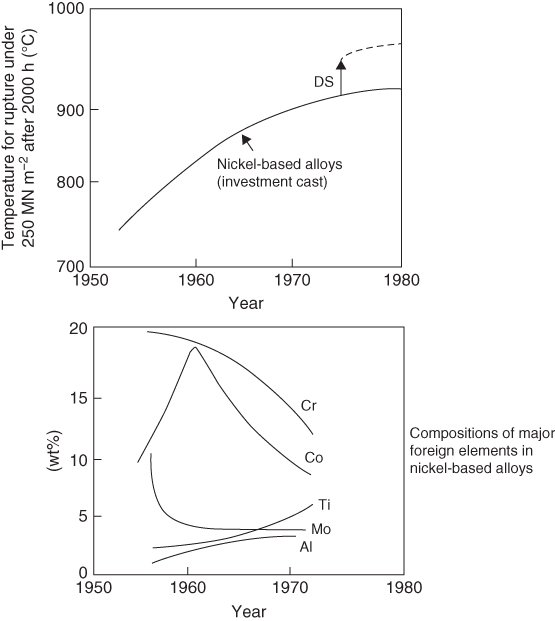
Matrix
Reinforcing phase
Reinforcing phase geometry
Ni
TaC
Fibers
Co
TaC
Fibers
Ni3Al
Ni3Nb
Plates
Co
Cr7C3
Fibers
Nb
Nb2C
Fibers
Material
Density (mg m−3)
Melting or decomposition (D), temperature (K)
Modulus (GN m−2)
Expansion coefficient × 10+6 (K−1)
Thermal conductivity at 1000 K (Wm−1 K−1)
Fracture toughness Kc (MN m−3/2)
Alumina, Al2O3
4.0
2320
360
6.9
7
≈5
Glass‐ceramics (pyroceramics)
2.7
>1700
≈120
≈3
≈3
≈3
Hot‐pressed silicon nitride, Si3N4
3.1
2173 (D)
310
3.1
16
≈5
Hot‐pressed silicon carbide, SiC
3.2
3000 (D)
≈420
4.3
60
≈3.5
Nickel alloys (Nimonics)
8.0
1600
200
12.5
12
≈100
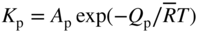 , where Ap and Qp are constants) is
20.3 Oxidation of Silicides for VLSI Applications
Silicide
Thin‐film resistivity (μΩ cm)
Sintering temperature (°C)
Stable on Si up to (°C)
Reaction with Al at (°C)
nm of Si consumed per nm of metal
nm of resulting silicide per nm of metal
Barrier height to n‐Si (eV)
PtSi
28–35
250–400
∼750
250
1.12
1.97
0.84
TiSi2 (C54)
13–16
700–900
∼900
450
2.27
2.51
0.58
TiSi2 (C49)
60–70
500–700
2.27
2.51
Co2Si
∼70
300–500
0.91
1.47
CoSi
100–150
400–600
1.82
2.02
CoSi2
14–20
600–800
∼950
400
3.64
3.52
0.65
NiSi
14–20
400–600
∼650
1.83
2.34
NiSi2
40–50
600–800
3.65
3.63
0.66
WSi2
30–70
1000
∼1000
500
2.53
2.58
0.67
MoSi2
40–100
800–1000
∼1000
500
2.56
2.59
0.64
TaSi2
35–55
800–1000
∼1000
500
2.21
2.41
0.59
20.3.1 Oxidation of Silicides on Silicon
Silicide
Dominant diffusion species during the following processes
Silicide formation
Silicide oxidation
TiSi2
Si
Si
CoSi2
—
Co
NiSi2
Ni
Ni
Pd2Si
Si, Si and Pd
Si
PdSi
Pd and Si
Pd
PtSi
Pt
Pt
CrSi2
Si
Cr
Moving species during oxidation
Schematic description
Experimental results


Si supply
TiSi2
Pd2Si

Dissociation
CoSi2
PdSi

“Excess” dissociation
CrSi2
NiSi2
PtSi

Dissociation and Si supply

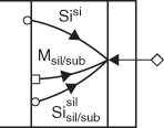
Si supply causes metal release and diffusion
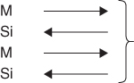
These processes do not preserve the silicide
20.3.2 Oxidation of Silicides on SiO2
20.4 Naphthenic Acid Corrosion in Petrochemical Plants


20.4.1 High TAN/Low Sulfur Environment
20.4.2 High TAN/High Sulfur Environment
20.5 Oxidation of Ceramic Matrix Composites
Application
Ceramics
Approximate use temperatures (°C)
Environment
Turbine engine components, combustor liners, blades, and vanes
SiC, Si3N4, composites
900–1400
Combustion gases, deposits: Na, Mg, Ca sulfates, sodium vanadates
Piston engine components, pistons, valves
SiC, Si3N4, composites
900–1400
Combustion gases
Industrial furnaces, heat exchangers
SiC, composites
900–1400
Combustion gases, various deposits
Coal combustion, particle filters
SiC, composites
700–1000
Combustion gases, slag deposits
Chemical process vessels, coal gasifiers, waste incinerators
SiC, Si3N4, composites
900–1400
Various gases: air, H2S, HCl
Re‐entry shields
SiC, composites
1000–1800
Reduced pressure: N2, O2, CO2, N, O
High temperature semiconductors
SiC
Use: 600
Processing: 1200
Air
Electronic substrates
AlN
Use: 600
Processing: 1200
Air
Fiber coatings for composites, crucibles, insulators
BN
900–1400
Fiber coatings: reduced pressure combustion gases, crucibles, vacuum, inert gases
Rocket engine throats
HfC, ZrC
1500–2000
H2/O2 combustion products
Liquid metal containers, processing and heat transfer
Transition metal carbides
600–1400
Vacuum or inert gas and liquid metals
20.6 Shell Corrosion of Rotary Cement Kilns
20.7 Corrosion of Steels in a Linear α Olefin Plant
References
Further Reading
Case Studies
20.1
20.2
20.3
20.4