Sarah Leeds DC Voltage Gradient Technology & Supply Ltd., Wigan, UK Cathodic protection (CP) is a very important technique for the mitigation of corrosion on buried or immersed structures such as pipelines. It involves an electrical current being applied to make the pipeline act as the cathode in a simulated electrochemical cell, hence, prevent the corrosion reaction from occurring at the pipe surface. The pipeline being protected must be exposed to an electrolyte such as buried in moist soil or seawater. CP is more advantageously used to protect coated structures because CP will only be required to protect uncoated portions of the pipeline and intact coatings will act as insulators reducing the amount of current required. If CP is not properly applied, it can have detrimental effects on the coating and ultimately the pipeline being protected. There are two methods for applying CP, namely, sacrificial anode cathodic protection system and impressed cathodic protection system. Sacrificial anode CP system is where an active metal is used as an anode (e.g., aluminum, zinc, or magnesium, etc.) and the potential between the active metal and the pipeline being protected forces the protective current to flow to areas of bare steel exposed on the buried pipeline. In an impressed CP system, an external power source forces the protective current to flow from an immersed anode to the pipeline to be protected through the conductive soil. It is important to make sure that the CP system is designed, installed, monitored, and maintained properly to ensure that the CP system will last the life span of the design. Knowledge of CP dates back to the Imperial Roman times of 27 BC–385 AD [1]. However, the science of CP was first established in 1824, when Sir Humphrey Davy [1] made a presentation to the Royal Society of London based on his experimental findings of protecting copper (which was used on ships’ bottoms to stop marine fouling) against corrosion from seawater through the use of cast iron anodes [2]. In 1834, Faraday discovered the quantitative connection between electrodeposition, corrosion, and electrical current, which lead to the scientific foundation of electrolysis and CP principles [3, 4]. Subsequently, without any knowledge of Davy’s work, Frischen, who was the Inspector of Telegraphs in Germany, reported to a meeting in Hanover in 1865, the results of experiments carried out over a long period looking into the protection of wrought iron, the most widely used metal at that time. Frischen connected zinc to iron for protection against seawater and was able to establish that effective protection of iron was due to the influence of galvanic electricity [1, 5]. In 1902, Cohen was the first person who successfully applied CP using an impressed current system. In 1906, Geppert, the manager of the public works in Karlsruhe, Germany, constructed the first CP system for pipelines using a direct current generator with a 10 V/12 A capacity to protect 300 m of gas and water pipelines close to a tramline [1]. In 1906, Deutscher Verein des Gas und Wasserfachs instigated a basic investigation into the scientific fundamentals of CP, which was carried out by Haber and Goldschmidt [6]. They recognized that CP and stray current corrosion were based on electrochemical phenomenon. Haber utilized a nonpolarized zinc sulfate electrode for potential measurement. Two years later, McCollum used the first copper sulfate electrode, which has since become the standard reference electrode for potential measurements of land-based systems [1]. Between 1910 and 1918, Bauer and Vogel in Berlin determined the current density required for CP [7]. In 1920, it was found that the Rhineland cable near Hanover, Germany, was damaged by the formation of corrosion couples in geologically mixed soil strata. This was the first time in Germany that zinc plates were built into the cable shafts to protect the sheathing metal from corrosion [1]. In the 1920s, introduction of safe, reliable welds allowed the laying of continuously welded pipelines and other structures making CP practically possible. However, this was not entirely achieved as engineers who built the pipelines had limited understanding of electrochemical protection, regarding it as a “black art” and even the electrical engineers underestimated the costs of the processes and the dangers that an applied CP current can have on other local pipelines. This resulted instead to improvements in the pipeline coating resistance to aggressive soils to reduce the effects of stray current corrosion. The lack of understanding and the limited interest in CP can be further acknowledged by the limited amount of information on CP in Evans’ first book on corrosion, which was published in 1924 [1]. From 1928 onward, development of CP as a practical application for pipelines was carried out in the United States. Kuhn, who is the undisputed “father of pipeline CP,” installed the first CP rectifier on a long-distance gas pipeline in New Orleans, the United States in 1928. Kuhn found that the protection of plain cast pipes, which had poorly conducting joints, did not extend beyond individual pipe joints, so he added more rectifiers. Through a series of experiments, Kuhn found that the polarized potential of −850 mV against a saturated copper/copper sulfate reference electrode (CSE) provided sufficient protection against corrosion. Kuhn reported what are now regarded as simplified results of his experiments to the Washington Conference for Corrosion Protection of the National Bureau of Standards in 1928. Kuhn’s findings formed the basis of modern CP technology. He was the first person who proposed that a polarized (OFF) protection potential should be −850 mV (CSE) as the value to be used for minimizing corrosion, which is a criterion still used today [8, 9]. The polarized potential is referred to as the IR-free potential or the instant OFF potential. The theoretical basis of CP was independently established through the work of Hoar [10] in the United Kingdom and Mears and Brown [11, 12] in the United States. The Mears and Brown work on CP is more widely acknowledged and their definition for obtaining complete protection is used most often in the CP industry; “in order that protection may be complete, the potential of the cathode area must be polarized to a potential equal to or more anodic than the open circuit potential of anodes.” Jones [12] in 1971 further substantiated the work of Mears and Brown by showing that the electrode kinetic theory could be applied to improve the understanding of CP. Jones claimed that the kinetics of the anodic dissolution reaction could be used to determine the cathodic polarization required for adequate protection. CP of pipelines in Europe began in Belgium and was widely applied later than in the United States. From 1932, de Brouwer applied CP to the supply pipelines of Distrigaz in Brussels, Belgium. In 1939, there were more than 500 cathodically protected pipelines in Russia, which were mostly utilizing galvanic anodes. CP utilizing galvanic anodes was carried out in the Great Britain and Germany after 1940 and 1950, respectively [1]. From humble beginnings, CP has grown to have many uses in marine; underground structures; water storage tanks; oil, gas, and water pipelines; oil platform supports; and many other facilities exposed to a corrosive environment. CP had become second to protective coatings, as the most widely used method for limiting the corrosion deterioration of metallic structures in contact with any forms of corrosive environments. It is generally assumed that the corrosion rate of a metal is controlled by the diffusion of oxygen dissolved in the bulk electrolyte solution to the metal surface. Figure 66.1 details a typical Evans diagram of steel in neutral aerated water. It can be seen that the corrosion rate of steel or the maximum consumption of electrons is limited by the rate of oxygen reduction. If no current is applied, then electron supply will be due to the dissolution of iron, which will then be equal to icorr. However, under application of CP, where the power source supplies the electrons, this will ultimately lead to a maximum applied current, icorr, which will then be equal to the limiting current density, iLim. Applying more current ultimately leads to the reduction of water, which causes the generation of hydrogen gas [13]. CP is a technique used to mitigate corrosion of a metallic structure. It involves applying a potential in such a way that the current flows from the anode through the surrounding electrolyte (moistened soil or seawater) to the structure surface. In concept, it is thought that if a sufficiently negative potential is applied, then corrosion of the metal structure should be mitigated. Figure 66.1 CP by impressed current density, iapp, for steel in neutral aerated water. Reference [13]/Prentice-Hall.) Application of CP causes two electrochemical reactions to occur: reduction of oxygen and reduction of water. The first reaction occurring as potentials become more negative is the reduction of oxygen dissolved in the electrolyte (moist soil or seawater) to form hydroxide ions. Reduction of oxygen is limited by the amount of available oxygen, which is typically 8 ppm dissolved in water (moist soil or seawater) at ambient temperature [14]. The limiting current density of this reaction is diffusion controlled. It has been found that when reduction of oxygen is the dominant reaction and occurs at applied potentials less negative than −1.17 V (CSE), then the typical pH of the metal surface is never more alkaline than 10.57 [15]. This is thought to be because there is such a small concentration of hydroxyl ions generated at the metal surface that the pH is limited because of the transfer of hydroxyl ions away from the metal surface. The second reaction that occurs is the reduction of water (cathodic reaction 2). This reaction normally occurs as the applied potential is made more negative than −1.17 V (CSE). This reaction is not controlled by any limiting current density but is controlled by diffusion and migration of ions to and from the metal surface. It has been found that as the applied potential was made more negative, the pH at the metal surface becomes progressively more alkaline. This can be explained by more hydroxide ions being retained on the metal surface when the surface films forming are becoming thicker, generating a more alkaline surface pH. The mixed-potential theory, as described in Figure 66.2 introduced in 1957, is the theory most thought today to explain the mechanism of cathodic protection. The mixed-potential theory is thought to be accomplished by polarizing the metal from its corrosion potential (Ecorr) to its redox/reversible potential (Eo,a). The amount of cathodic polarization depends on the amount of applied current, which is the difference between the anodic current at a particular potential. It can be seen that the anodic and cathodic species in a particular environment are combined. When cathodically polarizing the metal surface at some set potential, the point of εc on Figure 66.2 represents the amount of potential needed to be applied for there to be a potential change causing Ecorr to be shifted cathodically to its reversible or equilibrium potential ( Figure 66.2 Anodic and cathodic Tafel curves for the corrosion of a metal, M. Explanation for the mechanism of CP based on the mixed-potential theory. (Jones [35]/with permission of NACE International.) A Pourbaix diagram can be used to determine the propensity of a metal such as iron to corrode in solutions of varying pH and potential. The Pourbaix diagram can also be used to determine the region of immunity, which is the domain where iron is thermodynamically stable. The Pourbaix diagram can also determine the region of passivation, which is the domain where iron is covered by films of either Fe2O3 or Fe3O4 dependent on the electrolyte solution. The addition of anions to the electrolyte solution can have an effect on the thermodynamics of the metal reactions. In the case of addition of chlorides to the electrolyte solution, it can break down the films formed, which could lead to localized attack of the metal. When constructing the Pourbaix diagram for the Fe–H2O system, such as that constructed in Figure 66.3, it is important to define the conditions and it is assumed that temperature is 298 K (25 °C) and pressure of 1 atm. The solid species were considered to be Fe, Fe3O4, and Fe2O3 under these conditions. The Pourbaix diagram was plotted using a pH range between −2 and +16 and an electrode potential range between −1.8 and +2.2 VSHE. If the temperature and pressure are changed, a new Pourbaix diagram would have to be redrawn to fit these new conditions. Another factor to take into consideration when constructing a Pourbaix diagram for the Fe–H2O system is to define what ionic activity will represent “significant corrosion.” To determine what is considered to be corrosion relies on the amount of metal dissolution that is permissible under the defined conditions. It has been suggested that when the Pourbaix diagram such as in Figure 66.3 was constructed, then a solubility of 10−6 g atoms of soluble ion (iron) per liter was chosen to represent “no corrosion for all practical purposes” for the Fe–H2O system [18]. The E–pH Pourbaix diagram can be used to explain how CP works. Pourbaix suggested that CP can work by either lowering the metal (iron) potential into the region of immunity or by placing it in the region of passivation (Figure 66.3). Pourbaix suggested that to cathodically polarize iron into the region of passivity, it should be possible by anodically protecting or by passivating by alkalization. Pourbaix believed that to polarize iron into the region of passivity, the protection potential should be below the breakdown or pitting potential, so as to avoid localized corrosion or the growth of exiting pits. Figure 66.3 suggests that passivation of iron is only possible if the pH of the electrolyte is between 10 and 13 [17]. Figure 66.3 Potential–pH equilibrium (Pourbaix) diagram for iron in water at 25 °C. Considering Fe, Fe3O4, and Fe2O3 as solid substances. (Reference [17]/with permission of NACE International). A Pourbaix diagram can be used to predict how iron in the form of steel works to suppress the corrosion reaction when CP is applied. When CP is applied to a metal such as a pipeline, it is energized and has the effect of making the potential more negative. This causes the steel (iron) potential to move from its native potential to a more negative potential. This causes the steel (iron) potential to move so that it is in the region of immunity. In practice, this is not as simple as CP generates alkalinity due to the cathodic reaction with the production of hydroxyl ions. The effect of the cathodic-generated alkalinity is to move the potential not only in a negative direction but also toward a higher pH found in the region of passivity, which occurs before reaching immunity. Pourbaix recommended the following conditions to ensure CP by placing iron into the region of immunity as detailed in Table 66.1 [17]. It should be noted that the values detailed in Table 66.1 assume that the activity of iron (Fe) is 10−6 g ion/l and would represent no corrosion. Theoretically, the conditions in Table 66.1 are possible; however, this may not be so simple practically. The application of CP could mean that the corrosion of iron does not occur due to immunity but rather due to “cathodic passivity.” When determining the domain regions as set out in the Pourbaix diagram, all the conditions need to be adjusted for determining whether a metal will corrode or not. Table 66.1 CP Conditions for Immunity Source: Data on pH and voltage versus SHE from Ref. [17]. Data used for drawing E–pH Pourbaix diagrams for different metals detailed in the Atlas of Electrochemical Equilibria in Aqueous Solutions written by Marcel Pourbaix has been improved over the years through new research. CP can be achieved by using buried or immersed sacrificial anodes connected electrically to a structure/pipeline, which causes the corrosion potential to be lowered. The galvanic series or electromotive force (emf) series (Table 66.2) is used to determine the most suitable metal to be selected as an anode. Examples are magnesium, aluminum, or zinc as good anode metals. The other way to achieve CP is by an impressed current system where a source of external current is used in conjunction with an anode ground bed to suppress the corrosion. The choice between an impressed current and sacrificial anode system for a particular situation generally relates to one of economics, with the sacrificial anodes being more economical for smaller systems, while impressed current systems are more suited to larger installations. It also depends on environmental conditions of where the CP system will be utilized as sacrificial anodes are more suitable to a lower resistivity environment. Table 66.2 Electromotive Force Series of Metals a Half-cell potential in a one-molar solution of its own salts, measured with respect to hydrogen reference electrode at 25 °C. CP can be achieved by burying or immersing an electrode called a sacrificial or galvanic anode that is more electronegative than the metal, such as a steel pipeline to be protected, and then connecting it into the circuit. The current available from a sacrificial anode can be limited by the relatively low driving potential available (difference in the potential between the anode and structure such as pipeline, when referred to a common reference electrode) and the size that can be conveniently handled. Because of this, it is necessary to ensure a uniform distribution of the anodes over the structure unless the structure is well coated when generally only a few anodes are required [19]. Anodes may be buried or immersed at a distance from the surface of the metal to be protected and connected to it by means of an insulated conductor or alternatively may be directly attached to the surface of the structure such as pipeline. Direct attachment to the pipeline can be achieved satisfactorily if the electrolyte resistivity is low. However, when the electrolyte resistivity is high, adequate spacing of 5 or 10 m should be provided between the anode and pipeline to ensure that the available current is uniformly distributed. Figure 66.4 details a sacrificial anode CP system. Using sacrificial anodes as a means of protection involves the formation of a galvanic couple by connecting the pipeline to be protected to a more active material (i.e., the sacrificial anode), so the structure, sacrificial anode, and corrodent form an electrochemical cell. With the sacrificial anode method of protection, the maximum voltage that can be applied is equal to the emf of the electrochemical cell formed, whereas, in the case of an impressed current arrangement, any applied voltage in theory may be utilized. The fixed driving voltage can have a number of implications: Figure 66.4 Sacrificial anode CP system using magnesium as the anode. (Reference [18]/with permission of John Wiley & Sons.) The current output of a sacrificial anode depends upon the resistance of the anode to the electrolyte and the driving potential between the anode and the structure to be protected. From this, the output of the anode is determined by Ohm’s law: where The resistance R of the anode to the electrolyte is given by where This formula is based on a simplification of Dwight’s formula for calculating the resistances to ground [20]. From the simplified Dwight formula, it is evident that the resistance of an anode to an electrolyte depends on the electrolyte resistivity and the size and shape of the anode. For a given volume of anode material used, for example, in the form of a cylindrical rod, the resistance decreases if the length is increased. Thus, for electrolytes of high resistivity (e.g., most soils), anodes are generally in the form of rods or relatively slender castings, or in very high-resistivity surroundings, as extruded strip or ribbon. In seawater, which has a low resistivity, anodes generally are in the form of heavy castings or in extreme areas approximately spherical castings to minimize size. Anodes buried in soil are generally surrounded with a chemical backfill, which has a lower resistivity than the soil to reduce the circuit resistance and also to provide a suitable environment to ensure uniform corrosion of the anode material. Sacrificial anodes generally contain steel inserts, which maintain electrical continuity and mechanical strength of the anode material toward the end of its effective life. Where electrical cables are connected to the anodes to provide attachment to the structure, the cables are attached to the steel insert, with the cable insert connection being protected by a tar epoxy coating [1, 3, 4, 19]. The alloys that are used for sacrificial anodes are universally based on magnesium, zinc, or aluminum. The general performance of each of the galvanic anode types vary with the operating conditions such as electrolyte resistivity, temperature, and operating current density. Typical operating results for sacrificial anodes can be found in Table 66.3. Anode backfill is widely used to surround sacrificial anodes that are buried in earth. The backfill provides a uniform environment to promote anode consumption and maximum efficiency. It also isolates the anode material from direct contact with the earth, which prevents negative effects from soil minerals that might build up high-resistance films on the anode surface. Examples of backfill used for magnesium sacrificial anodes are 75% hydrated gypsum, 20% bentonite clay, and 5% sodium sulfate. A typical mixture utilized with zinc anodes consists of 50% plaster of paris and 50% bentonite clay. Impressed current systems are like sacrificial anode systems in the sense that electrical currents are used to control corrosion flow from one or more anodes to the structure to be protected. An impressed current system, however, requires an external direct current source, such as a rectifier typically called transformer/rectifier (T/R) to impress current through an anode, which provides a very low corrosion rate. This controls the magnitude and direction of the current flow used for CP. Table 66.3 Typical Sacrificial Anode Characteristics Source: Reference [1]/with permission of Elsevier. The most important characteristic of materials utilized for impressed current anode groundbeds is a low consumption rate, which in most instances is related to current density at the surface of the anode. Most often the anodes utilized are made from low consumption alloys such as graphite, high-silicon cast iron, platinum, and ceramics (e.g., Si–Fe, Pb–Sb, Sb–Ag, or Pt–Ti). Graphite and high-silicon cast iron are commonly used for buried installations. High-silicon cast iron, platinum, and ceramics are commonly used in fresh water and seawater applications. Chlorine or oxygen is normally evolved at the inert impressed current anodes. Figure 66.5 details a general impressed current CP system. The figure shows how a group of anodes are installed remotely (typically 100 ft. or more) from the pipeline and usually spaced on 10–30 ft. centers and make up the groundbed that comes with back fill. The rectifier, typically called T/R, supplies the power source but power sources can also be supplied by solar cells, engine generator sets, wind powered generators, and turbine generators. Groundbeds are not really providing the driving power for the CP system, but instead an external source of direct electric current is connected between the structure to be protected and the groundbed anodes. The positive terminal of the power source is required to be connected to the groundbed, which will be forced to discharge as much current as possible. If a mistake is made and the positive terminal is connected to the structure, then the structure will become the anode and will actively corrode. Figure 66.5 Impressed current system for a buried pipeline. There are several main factors that should be taken into consideration when selecting a site to be utilized as a groundbed site: The power supply availability, accessibility to the groundbed for testing and maintenance, and any third-party effect such as vandalism of the groundbed should be taken into consideration when selecting a groundbed site. Groundbeds are forced to discharge current and will corrode. Thus, it is important to provide anode material that is consumed at relatively low rates. Materials such as scrap steel pipe, rail, rod, etc., may be used, but they tend to be consumed at the rate of 44 kg per ampere/year (one ampere flowing for 1 year). Thus, a large amount of material will be required for a desired operating life. There are various anodes that are available for use, but the design life should be calculated to determine whether they are suitable. These include graphite, platinized anodes, mixed metal oxide coated anodes, etc. The type of anode groundbed used is dependent on the design. Anode groundbeds are either located close to the structure being protected or remotely, so that the current can be distributed over the entire structure to be protected. Anode groundbeds are either local distributed anode groundbed system, vertical distributed anode groundbed system, horizontal distributed anode groundbed system, deep anode groundbed, or remote anode groundbed system. The location of the anode groundbed is relative to the structure being protected and other structures in the vicinity are very important in minimizing shielding effects. Typically, coke or graphite back fill is used to surround anodes used in impressed current CP systems. Figures 66.6 and 66.7 detail CP systems utilizing anodes in soil and water conditions [1, 3, 4]. The major difference between a sacrificial anode and impressed current CP system that will determine the type of system chosen is the difference in the driving voltage attainable, and therefore, the current output. A sacrificial anode system has a driving voltage limited by the emf of the galvanic cell set up between the anode and the structure; for example, −1.5 V for a magnesium anode and steel structure; whereas, an impressed current system is free from this restriction, and different design techniques are employed to take advantage of this. If protecting a large structure such as a pipeline, then utilizing sacrificial anodes would require a large number of them distributed along the pipeline, which would involve a multitude of electrical connections and a lot of installation work. While an impressed current CP system being utilized to protect the same pipeline would require a smaller number of anodes, each fed with a greater current, though it would require a higher driving voltage of about 20 V to achieve protection. An undesirable feature of protecting the pipeline this way is that certain sections of the pipeline may be overprotected in achieving complete protection in other parts of the pipeline. This is always seen on a pipeline where the relative nearness of the anode and groundbed and buildup of voltage in the pipe metal causes local overprotection. Often a pipeline is overprotected from one anode position because overall protection can be more easily obtained from one anode than from a number of smaller anodes, which could cause a more even protection [19]. Figure 66.6 Impressed current CP system for a buried pipeline in soil. Figure 66.7 Impressed current CP system for a structure in seawater. (Reference [21]/with permission of Marine Technology Directorate.) Generally, any decision taken to install one type of CP system over another requires careful consideration. Generally, a compromise is used and may include a combination of both systems. Parameters that may affect the decision of which CP system to use are Sacrificial anodes are infrequently used in soils where the resistivity is in excess of 75 ohm.m. However, a structure protected by sacrificial anodes generally requires less frequent monitoring and is self-controlling. See Table 66.4 for a summary of the comparison between sacrificial anode and impressed current CP systems. Table 66.4 Summary of the Comparison Between Sacrificial Anode and Impressed Current Systems Methods for designing CP systems can be rather complex but basically it can be split up into three different questions: Usually, the amount of current supplied to a CP system or on a specific exposed area is based on past experience or on actual measurements, which have been taken at that particular CP system location. The current required to protect a new structure is calculated according to its overall exposed area. Another method of calculating the current requirement is that the structure to be protected should be preinstalled. Then, electrical measurements should be performed directly to determine the current requirement for protection of that particular structure. There are two different ways of supplying a CP system, and each has its own requirement for how to provide the estimated current. If sacrificial anodes are chosen as the way of supplying CP, then the type of anode material must be chosen and the number of anodes to be used must be calculated. The anode life can be calculated to determine the most suitable anodes to use. The type and size of anode material used can be adjusted accordingly to ensure that it produces the required current for the desired anode life for the most economic cost. The type of anode material and the number and sizes of anodes required depends on the corrosivity of the environment, which can be obtained through the resistivity of the electrolyte. The resistivity can then be used to calculate the output from a single anode of a particular size and type of material used. The number of anodes then required for the CP system is calculated by dividing the total current required by the output from a single anode. The anode life can be calculated by determining the amount of active material that is present in the anode and the current provided. Thus, the weight of the anode material being consumed is proportional to the amount of current being provided. If an impressed current system is chosen, then the system is designed as a simple direct current circuit. The most important variables to this circuit are the resistances of the components making up the system, in particular, anode resistance. The anode resistance is dependent on the number and size of the anodes used and the resistivity of the environment. It is more desirable to have an overall low resistance as this will reduce the amount of voltage required to provide the required current to run the CP system. For a given current requirement, a lower overall resistance and resultant lower voltage will cause lower power costs and make a more economic system. For underground anode installations, an electrically conductive material is utilized such as coke breeze and is placed around the buried anodes. This electrically conductive material has the effect of reducing the electrical resistance by increasing their effective size. For further reduction of the resistance of the anodes, it will require the installation of more anodes or larger sized anodes. If there is a requirement for more or larger sized anodes, then the expense of this must be balanced against the increased costs of the T/R and power costs associated with higher voltages. As with sacrificial anode systems, the factors involved in supplying an impressed current system must also be balanced in the overall design of the CP system to ensure that the cost is minimized but while still maintaining an overall effective CP system. This final question for the design of a CP system depends on the system configuration, be it for a sacrificial anode CP system or an impressed current CP system. Several different real-case scenarios are examined for a better understanding of how the current is distributed over the whole structure of the CP system. The function of a coating is to reduce the area of metal exposed to the electrolyte, which enables the current density required for CP to be greatly reduced. Even a coating in a poor condition can reduce its current requirement by approximately 80–90%. A reduction in current required will reduce the cost and extend the life of the CP system. Also, it can reduce the undesirable side effects such as stray currents that occur when large amounts of current are required. For both seawater and buried pipeline conditions, a protective coating used in conjunction with CP can be far more economical way of applying CP as coatings will act as the premier method for stopping corrosion. The basic requirements of pipeline coatings are summarized as follows: Materials used for pipeline coatings range from fusion-bonded epoxy, extruded polythene, asphaltic enamel coal tar, or plastic tapes. The choice of the coating type utilized depends on a large number of factors, although the final aim should be to achieve the best overall economy in the combined cost of protected structure and the initial and running cost of the protection schemes. It is generally accepted that the highest quality coatings are provided by the coal tar enamels and the extruded polythenes [18, 23]. Table 66.5 Coating Resistance Against Current Requirement Source: Reference [23]/with permission of NACE International. The importance of coating resistance in terms of reducing the current required for CP is given in Table 26, which details the protective current requirement for 10 mi. of 36 in. diameter pipe with varying quality of protective coating (Table 66.5). CP can have beneficial and adverse effects on the performance of protective coatings depending on the particular situation. Some of these effects are listed in the following section. If the CP system is not properly designed and operated, or if the coating system is not properly selected to be compatible with the CP system, then three problems may occur: Figure 66.8 Mechanism of electroendosmosis. (Reference [24]/National Institute of Standards and Technology/Public Domain.) Specific tests can be found in various standards such as those provided by American Society for Testing and Materials (ASTM) such as G8, G9, G19, G42, G80, and G95, which can be used to evaluate the resistance of coatings to damages that can be caused by alkalinity, cathodic disbondment, and electroendosmosis [24–30]. All CP systems require routine monitoring to make sure that the systems are running efficiently and effectively to prevent corrosion and subsequent metal loss from occurring, which could be very costly or cause environmental damage or be harmful to human life. Most often CP systems require a periodic inspection and subsequent maintenance to keep optimum performance of the system. Sacrificial anode system inspection requirements are fairly minimal. Typically, they require some sort of inspection program every set time interval, which can be 6 monthly to yearly. A typical inspection of the system requires electrical measurements of the structure at several points within the system every set time interval. In most cases, test stations are the locations for performing the measurements and are usually installed as a permanent part of the CP system.Typically test stations, have connection wires for testing the system and are usually located within an enclosure. The potential readings recorded at the test stations can be used to indicate whether there is a problem with the CP system. Analyzing the potential readings can be used to assess whether there is a need for a more thorough survey consisting of potential measurements taken at locations along the structure and the current output measurement of the anodes of that particular CP system. The most common problem associated with a sacrificial anode system is the consumption of the anode and the breaking of the wires from the anode to the structure. Impressed current CP system requires more frequent inspections. Typical inspection plans involve inspections every month of T/R to determine the amount of current and voltage being provided to the CP system. Potential measurements will then be taken of the structure between every 6 months and every 12 months. This will determine if there is a problem within the CP system and what maintenance is required and if any other tests are required. There are several different survey techniques that are used to monitor CP systems to determine its functionality. Standard test point and annual compliance surveys are used to monitor CP performance. The direct current voltage gradient (DCVG) is used to locate coating faults in buried pipelines and determine the severity of the coating faults. The DCVG technique can also assign a corrosion status of each coating fault. The close interval potential surveys (CIPS/CIS) are used to monitor the efficiency of the CP system. Soil resistivity is used to identify corrosive soil areas where the pipeline is located and determine the likelihood of metal loss at these areas. Commissioning is used by a CP engineer to verify that the CP system has been installed correctly as that outlined during the design of the system. The CP system should be started, then verification of the CP effectiveness should be investigated, and adjustments should be made if required to ensure that CP is applied to the whole pipeline. During initial stages of commissioning of a CP system, before the CP system has been switched on, all electrical installations should be carried out by the appropriate electrical engineer according to the local regulations. Prior to energizing the CP system, all the circuits, T/R, electrical drainage stations, isolation joints, earthing devices, metallic casings, monitoring test stations, coupons, and working electrodes should be checked to verify that they have been installed correctly and are functioning correctly. Potential measurements should be made of the corrosion potential of all structures on the test stations to verify these. Resistance measurements should be measured at remote earth for groundbed or sacrificial anode locations and resistance between the pipeline being protected and the groundbed. The influence of an AC or DC sources toward the pipeline should be investigated. The anode-to-electrolyte potential of sacrificial anodes should be measured. The pipe-to-electrolyte potential of any neighboring foreign pipelines should be investigated [31]. During the energizing of the CP system, it involves the following procedures: Pipelines generally have monitoring facilities installed along the pipeline route to check that CP is being supplied to all parts of the pipeline. Monitoring test stations are usually installed above the pipeline but with connection to the pipeline. Within the test station, there should be at least two separate cables that are connected directly to the pipeline. Each cable within the test station should be color coded to identify what they are. Typically, pipe-to-soil potentials, current, and possible interference are monitored at test stations. Test stations are usually installed on pipelines at a distance no longer than 3 km and in urban and industrial locations they are installed at intervals no longer than 1 km [31] Monitoring test stations are installed at crossings, isolating joints, at connections to earthing systems, metallic casings, bond connections to other pipelines or structures, and other connections that have coupons or groundings attached to them. Monitoring test stations should also be installed on pipelines where the pipeline crosses other pipelines, where they cross major roads or dikes, where pipelines cross railways and rivers, and where the pipeline runs close to other structures. Ideally, if several pipelines run in parallel such as in a corridor but not in the same trench then each pipeline should be provided with separate potential monitoring facilities. Pipelines should be bonded where a pipeline crosses another pipeline. The bonding should consist of two separate cables, each connected to each of the individual pipeline, which should terminate within the test station and have a facility to install direct or resistive bonds when needed. At impressed current stations, the T/R output voltage should be checked, the protection current output should be checked and the ON potential at the drain point should be checked. Sacrificial anodes should be checked to verify the protective output of each sacrificial anode and the equipotential of each bond current. At the test stations, the ON potentials should be carried out at the extremities of the pipeline. The ON potential and current should be measured for any coupons installed at the test stations. The pipe to electrolyte of neighboring pipelines should be measured to assess any influence these may have on the pipeline of interest. The ON potential should be measured to determine any electrical isolation of the pipeline at the isolating joints, metal casings, any reinforced concrete sections, and at any earthing systems. The ON potential and current should be measured at the bonding sections on the pipeline. The AC voltage should be measured on the pipeline to determine any likelihood of interference. The methods for carrying out the measurements that are required to be taken should be carried out according to local standards and specifications such as NACE TM0497:2018 Product No. 21231-SG [32] or in accordance with the procedures set out in the very comprehensive NACE book, Cathodic Protection Survey Procedures, 3rd edition, by Holtsbaum [22]. Inspection and monitoring of CP systems should be carried out at regular intervals, and in some countries, it is a legal requirement to carry out these surveys to determine that the protection criteria are being fulfilled and to determine any deficiencies with the CP system. There are routine measurements and checks that should be taken out annually or as specified legal requirements or determined in standards. Table 66.6 details some routine annual inspections and the frequency at which these measurements should be taken. The frequency of carrying out the measurements can be increased in areas where there is stray current interference or at critical sites and where there are foreign connections. If CP systems are monitored remotely, any equipment malfunctions can be easily determined from the first available data transmission rather than measurements carried out monthly or annually. Information regarding the methods for carrying out these measurements can be found in NACE standards such as NACE Standard TM0497:2018 or in the NACE book, Cathodic Protection Survey Procedures, 3rd edition, by Holtsbaum [22]. In CP when current flows through the resistive soil to the bare steel exposed at coating faults in the protective coating, a voltage gradient is generated in the soil. This voltage gradient will form and dissipate as the CP system is switched ON and OFF. The larger the coating fault, the greater the current flow, and hence, voltage gradient, and this is utilized in the DCVG technique to prioritize coating faults for repair. Table 66.6 Routine Compliance Surveys and Frequency of Measurements Source: Adapted from Ref. [31]. a Where stray current may influence VOFF potential measurements then alternative measurement techniques maybe required. The following are examples of just a few of the types of suitable applications of the DCVG technique: During a DCVG survey, a voltage gradient is observed by measuring the out-of-balance between two CSEs utilizing a specially designed millivoltmeter. The CSEs do not need to be saturated because when carrying out a DCVG survey, you are not measuring to a reference electrode but by measuring the difference between two CSEs. The concentration of the copper sulfate solution when carrying out a DCVG survey is typically between 1% and 5%. Why don’t we just use water as not measuring by a reference? Using the typical DCVG CSE probes which consist of a long copper rod with a wooden probe tip then an electrochemical reaction will still occur between the copper metal of the probe and the copper sulfate solution. Also, there may be contaminates in water that are not wanted in the DCVG reference probes, which is why it is typically recommended to make up the copper sulfate solution with distilled or deionized water. When carrying out a DCVG survey, the surveyor positions themselves directly on top of the pipeline with the two electrodes placed 1–1.5 m apart on the soil which are parallel to the direction of the buried pipeline. The surveyor will be facing toward the direction of the pipeline. The voltage gradient from a coating fault will be traced; one electrode adopts a more positive potential than the other, which allows the direction of current flow to be established and coating fault to be located. To simplify the coating fault location interpretation, the applied CP is separated from all other DC influences such as tellurics, DC traction, and so on, by pulsing the local CP ON and OFF in an unsymmetrical fashion. The pulsing DC can be from the pipeline CP system itself, or from an independent source such as a portable DC generator or batteries utilizing a temporary groundbed and impressed on top of a pipelines existing CP system. Typically, a 1.25 second pulse time is chosen as the pulsing CP ON and OFF sequence. This is chosen to match the response time of the surveyor to interpret the direction and amplitude of the DCVG needle movement. If this is a long pulse time, the surveyor will be waiting on the pulse which will hinder interpretation and slow down the survey. If the pulse time is shorter, there is not only the inability to interpret but the anodic and cathodic spikes which are the phenomenon that occurs when switching the CP system ON and OFF will limit interpretation. This type of anodic and cathodic spikes formation depends not only on the design of the rectifier/CP DC source but also on the electrical reactance of the pipeline in the ground. DCVG meters should be designed to provide residence time at the end of each pulse but also to limit overswing that can be observed in analog meter movements. The success of a DCVG pipeline coating survey depends on two factors: the application of a large enough DCVG signal at a coating fault so that the voltage gradient can be detected in the soil surface, and having a sensitive detection meter able to sense the voltage gradient. The magnitude of a typical detection signal and the rate of decay down the pipeline depends upon the complexity of the buried pipework arrays. The number and severity of each coating fault will have a dominating effect on the signal-decay rate of the impressed DCVG signal. The DCVG surveyor will read the scale of the survey meter and obtain an accurate measurement of the needle deflection, which is the amplitude of the pulse on the meter. The first position of the needle is read when the interrupter is in the OFF status. The deflection position of the needle is read when the interrupter is in the ON status. The amplitude of the pulse is the ON value read on the meter minus (subtract) the OFF value read on the meter. The signal strength at a typical test post is the difference in millivolts (mV) between the deflection and the rest position of the needle. A typical measurement should be between 100 and 1250 mV. Typical signal strengths utilized for new pipelines, pipelines buried at some depth and pipelines located in subsea locations should be increased to 1500–2000 mV. It is possible to survey using a signal strength as low as 40 mV but you will miss very small coating faults. To obtain the total DCVG signal on the pipeline, an additional measurement is required and that is the gradient in the soil from the base of the test post to remote earth. In the DCVG technique, all electrical measurements are taken from the test post or from the coating fault epicenter to remote earth to ensure the full voltage gradient is included in the measurement. A DCVG survey starts from the first test post/point along the pipeline route. Signal strength is measured from the test post/point to remote earth, either using a long cable or using a stepping out to remote earth reaching remote earth when a small value close to zero is recorded for two consequent values. See Figures 66.9 and 66.10, which show the electrical measurements taken at the test posts/points and at the location of the coating fault epicenter, which is termed the overline to remote earth (OL/RE) during a DCVG survey. These measurements can be taken using a step out procedure or using a single long cable as detailed in Figures 66.9 and 66.10. Figure 66.11 details a DCVG Signal Amplitude Data of 384 mV taken from test point/post to remote earth measurement for seven transformer/rectifiers from actual pipeline data as an example. A stepped-out method was used to obtain the data. Remote earth is taken as a distance of 15 m out at 90° to the pipeline and is a distance found to be adequate for most conditions but if the soil resistivity is high, say 250,000 ohm-cm, then greater lateral distances may be required. Typically test at 10 m and then at 15 m then if two readings are very similar you have reached remote earth. Figure 66.12 details test point/post to remote earth signal amplitude data when there is a coating fault within the vicinity of the test point/post. The second stepped out measurement increases compared to the first measurement taken and decays until it reaches remote earth. Figure 66.9 Test postmeasurements. Figure 66.10 DCVG signal amplitude to remote earth using a long cable. It is essential to take measurements at all test posts/points along the pipeline route during a survey and not just the first and very last test post/point to reduce error in the data. These measurements are then required to calculate the pipe to remote earth that is used in the %IR severity calculation. A DCVG operator starts surveying a pipeline, the operator walks the pipeline route with the meter set to the most sensitive range, 10 mV, adjusting the meter needle onto the scale using the bias handle testing for a pulsing voltage gradient at regular intervals and adjusting the meter range accordingly. As a coating fault is approached, the operator will observe that the millivoltmeter needle begins to respond to the pulse, pointing in the direction of current flow that is toward the coating fault. When the coating fault is passed, the needle direction completely reverses and slowly decreases as the surveyor moves away from the coating fault. By retracing to the coating fault, a position of the electrodes can be found where the needle shows no deflection in either direction (a null). The coating fault is then sited midway between the two electrodes. This procedure is then repeated at right angles to the first set of observations, and where the two midway positions cross is the epicenter of the voltage gradient. This is usually directly above the coating fault. The quadrant check or four points of a compass is the final determination of a coating fault epicenter. The surveyor places the left-hand CSE reference probe on the epicenter position and the right-hand probe is positioned 2 m away. At each 90° position/positions of the compass, the survey meter should indicate a deflection pulse that is toward the coating fault epicenter. North position is always considered the direction of flow of the fluid in the pipeline. Figure 66.11 DCVG signal amplitude measured using the step out procedure. Figure 66.12 DCVG signal amplitude with coating fault in the vicinity of test post/point. The DCVG technique utilizes the existing pipeline CP system at its normal setting wherever possible, and hence, the results reflect the intimate interaction between the protective coating degradation and the effectiveness of CP at individual coating faults. This is very powerful information in the fight against corrosion. The DCVG technique can be applied in city streets, process plant and refineries, across rivers and estuaries, swamps, parallel pipeline systems, to gas, oil, chemical, and water pipelines. Also, DCVG can be used to evaluate the protective coating on telephone and power cables. Figure 66.13 details the response of the analog DCVG meter as an operator is surveying the pipeline. Figure 66.14 details an actual DCVG operator surveying above a pipeline. Examples of coating faults that can be located using DCVG are illustrated in Figure 66.15. To determine various characteristics about a coating fault, such as severity, shape, corrosion behavior, etc., various electrical measurements around the epicenter and from epicenter to remote earth are made for interpretation. During the quadrant check, if the spacing of the reference probes is kept the same, 2 m, for all four positions, it is possible to identify the probable coating fault position around the pipeline. If all four positions of the compass signal amplitudes are the same value, then the coating fault is positioned on the top of the pipeline. If the two lateral measurements are bigger than down the length of the pipeline, the coating fault is on the bottom of the pipeline. If the right-hand side lateral is bigger than the left-hand side lateral, then the coating fault is on the bottom of the pipeline at the right-hand side; and likewise, with the left-hand side being greater than the right-hand side, then the coating fault is on the bottom of the pipeline located on the left-hand side. The overline to remote earth is measured from the coating fault epicenter to remote earth in a similar fashion to the measurement made at the test posts/points signal strength or swing shift. The signal amplitude or swing shift is read when the meter needle is pulsing. The overline to remote earth is used in the %IR severity calculation. The DCVG technique uses the flow of current in the soil to determine the coating fault location. These currents can be characterized to determine whether the coating fault is protected, or if possible corrosion is occurring. By definition, current flowing toward a coating fault is protective and termed cathodic, and current flowing away from the coating fault giving rise to possible corrosion is termed anodic. Figure 66.13 Diagrammatic representation of what occurs during a DCVG survey. Figure 66.14 Surveyor carrying out a DCVG survey on a buried pipeline. A coating fault will not corrode if an adequate level of CP is maintained at the coating fault location. Conversely, corrosion will occur at a coating fault when the level of CP at the coating fault location is inadequate. In terms of current flow, it would mean the net current flow is flowing toward the coating fault, the coating fault will be protected, and if the total current is flowing away, then the coating fault is possibly corroding, the rate being determined by the amount of current flowing. If the detected coating fault is indicated by the survey meter observations to be anodic behavior, then it becomes a possible candidate for excavation. Having noted the outcome of the excavation, the results can be used as a guide for any similar anodic behavior for similar soil conditions at the same site. Many anodic coating faults have been identified as small in %IR severity and on excavation, found to be associated with coating disbondment. Situations whereby the coating fault appears to be anodic while the CP current is switched ON should be investigated as likely areas for corrosion damage. This occurs when the background DC current shows anodic behavior that cannot be sufficiently countered by CP. Adjustments to the CP transformer/rectifier output can usually influence the protection behavior by changing it from anodic/anodic to anodic/cathodic. The corrosion status of a coating fault is determined after locating the coating fault. After center zeroing the analog meter at remote earth and then leaving one reference probe at remote earth and one at the coating fault epicenter, the needle movement is observed on the meter. Of the four possible meter needle configurations, one is observed while the CP system is switched ON and OFF: Figure 66.15 Examples of coating defects that can be located by DCVG. Figure 66.16 Four corrosion status identified on DCVG meter. See Figure 66.16 for details about the four possible meter indications to determine the corrosion status of the coating fault as identified on the DCVG meter. All buried pipelines and structures have coating damage, and coating faults occur in different shapes and sizes. The common factor in the variety of damage is that all of the coating faults will have a voltage gradient epicenter for the bared steel, which is in contact with corrosive soil and under CP. The evidence from excavating many thousands of coating faults has led to two main conclusions: (1) The need to understand severity and its repair importance, which provides information enabling %IR severity assessment to be made. (2) More often than not, the usual case is to find that two types of coating provide protection against the electrochemical corrosion reaction, the organic (paint, FBE, etc.) and inorganic (surface films such as magnetite) coatings. The general thought is that the corrosion opportunity at every coating fault can be contained by an effective CP system. This assumption is a delicate balance and can be upset as the severity of the coating fault increases, while the CP system becomes more and more ineffective in its protection. The DCVG survey technique can accurately “fingerprint a pipeline” by locating the epicenter of any coating faults. From electrical measurements, the severity of the coating fault can be assessed and then graded into four categories, which are based on practical experience. The importance of each category will prioritize any immediate or future refurbishment of the coating and any rehabilitation of the pipeline and its CP system. The relative severity of a coating fault is expressed by the term %IR, which is calculated using the following formula: Calculation of the pipe-to-remote earth potential (PRE) is an important figure needed to calculate the severity (%IR) value for a coating fault. To be able to calculate the severity (%IR) of coating faults, it is necessary to know the distance of coating faults and the DCVG signal strengths at test posts either side of the sector being surveyed. The pipe-to-remote earth potential (PRE) is calculated as follows: where In the example given in Figure 66.17, the severity of a coating fault (%IR) is calculated as follows: Overline to remote earth from Figure 66.17 is 130 mV. Pipe-to-remote earth is calculated using the formulas given previously and using the values given in Figure 66.17; then What does this figure of 21.7% mean? Because the severity of a coating fault is calculated from electrical measurements of the voltage gradient, the results obtained are dependent upon the current flowing to each coating fault and soil/film resistivity. The current flowing depends upon how large the coating fault is, how well protective films of magnetite have grown on the exposed steel surface, and how close the coating fault is to the CP drain point. Resistivity affects current flow, and hence, voltage gradient. By resistivity, we mean a combination of soil resistivity and the resistivity of films of corrosion product on the exposed steel surface. The latter resistivity can be quite large, that is, 100,000 ohm/cm2 of surface area. Ideally, all measurements should be converted to a standard soil resistivity; we have chosen 5000 ohm-cm. Figure 66.17 %IR severity of a coating fault. This has allowed coating faults to be graded to determine those that should be repaired from those that it is possible to live with. Please note on new pipelines most of the %IR values will be very small. The pipeline operator will determine if all small %IR defects should be repaired or not. So, under the %IR severity grading, 21.7% would be classified as a medium severity coating fault. The coating fault grading is We tend to describe coating faults as severity rather than size. The coating fault excavated is not always the same size as it was when buried. Soil can hold the coating fault in place and thereby provide a means of protection, but when the soil is removed the coating can relax, often dry out and curling away from the pipe indicating a size of the coating fault that is much larger than if the soil was not excavated. One dominating influence on the relationship between %IR severity is the effect of the surface film that grows on the steel surface exposed at coating faults. If the pipeline is under effective CP, the exposed steel at the coating fault grows a protective black magnetite film. A white calcareous deposit can also form if the pipelines environment contains carbonates and can also form on top of the black magnetite film as well. If the CP is ineffective, then films of red rust such as ferric oxide grow on the steel surface. The surface film growth is dependent on soil pH, chemistry, and amount of CP present at the coating fault. In particular, an alkali environment which forms upon the application of CP causes the growth of the surface films. The surface film blocks off the steel surface thereby reducing the exposed steel surface and hence the amount of CP current flowing to the coating fault and its %IR severity. On the other hand, surface films do not form in environments of acidic soils such as in forests or peat areas, then large amounts of current can flow to the steel surface exposed at small amount of damage to the protective coating. As an example of a grading comparison, the severity of a coating fault in an alkaline soil could be graded as a 15% IR severity rating, a small coating fault. The same size coating fault in acidic soil because of poor or nonexistent magnetite surface film formation could be graded as a 55% IR severity rating, a medium/large coating fault for repair. The aforementioned characterizations of coating faults are only one input but a very important input to the excavation and repair decision. Other important factors are shape and method of coating failure, corrosion behavior, soil pH and resistivity, presence of hydrogen sulfide in the soil, operating temperature, age, coating type, pipe-to-soil potentials, leak and metal loss history, and so on. An example of the sorts of graphs that are produced during a DCVG survey for the %IR severity versus distance is detailed in Figure 66.18. Figure 66.18 Example of DCVG data: %IR severity versus distance. The theory behind the CIPS/CIS is to measure pipe-to-soil potential along the whole pipeline by taking readings at regular intervals (1 m). The CIPS/CIS surveyor carries a CIPS/CIS datalogger connected to saturated CSE reference electrodes, typically two are used, one connected to each other to ensure one CSE is always in contact with the ground directly over the pipeline as the surveyor walks along the pipeline route. The copper trailing wire from the CIPS/CIS datalogger is connected to the pipeline via a test point/test post. As many synchronized interrupters as required are used to pulse the CP ON and OFF to obtain a pipe-to-soil potential profile for the entire pipeline. Such potentials are then interpreted according to general criteria such as the −850 mV CSE criteria originating largely from one of the NACE/AMPP criteria, for example, SP0169-2013, as to what constitutes the potential divide between protection and under protection. Typically, the pipeline right-of-way should be identified either before carrying out a CIPS/CIS survey or one operator walks ahead of the CIPS/CIS operator and locates the pipeline using a pipe locator. CIPS/CIS surveys are often quite demanding as it requires the operator to walk the entire right-of-way. The copper wire can also be broken many times along the pipeline when the operator encounters obstacles such as road crossings, fences, etc. One important consideration of a CIPS/CIS survey is the ohmic (IR) drop error that is included in the potential measurement when the CP system is operational. Most often instant OFF measurements are made to correct for the IR drop. However, it is not always easy to make IR-free measurements because some currents cannot be easily interrupted such as sacrificial anodes, which are directly bonded to the structure, foreign T/R, stray currents, telluric currents, and long-line cells. Interrupters are generally used to switch the CP system ON and OFF for a limited amount of time, which ensures that depolarization of the pipeline occurs gradually due to the accumulative effect of switching the CP OFF. Typically, all T/R along the pipeline under inspection are synchronized to switch ON and OFF at the same time. The CP system should be switched ON and OFF in such a way that it avoids capacitive spikes that occur shortly after the current is interrupted as this may hide the instant OFF potential. Utilizing data loggers that have been synchronized with the interrupters will avoid this problem and make sure that the data are recorded at the correct intervals. It is a preference to have some sort of GPS system as a distance measurement for greater accuracy to pin point where data have been taken. At the epicenter of the coating fault, the voltage gradient shows the least negative potential and is the ideal position for the CIPS/CIS measurements. Figure 66.19 details how CIPS/CIS measurements should be taken. Figure 66.20 shows a surveyor carrying out a CIPS/CIS survey. An example of the sort of graph that are produced during a CIPS/CIS pipe-to-soil potential survey is detailed in Figure 66.21. This data is exponentially corrected pipe-to-soil potentials taken at coating fault locations. The graph shows areas that do not meet the −850 mV CSE criteria. The ON pipe-to-soil potential should not be more negative than −1200 mV CSE to prevent damage to the coating system. The OFF pipe-to-soil potential should not be less negative than −850 mV CSE to ensure adequate protection to prevent corrosion. Figure 66.19 Diagrammatic representation of CIPS/CIS method. Figure 66.20 Surveyor carrying out a CIPS/CIS survey on a buried pipeline. Soil resistivity is an inverse function of soil moisture and the concentration of soluble salts available. Generally, most soil and rock minerals are highly resistive. Current flows primarily through moisture-filled pore spaces and cracks in soils and rocks. It can be assumed that soil resistivity must, therefore, be predominantly controlled by pore spaces, cracks, and the amount and composition of water filling the pore spaces. Soil resistivity has been historically used as a broad indicator of soil corrosivity. Ionic current flow is associated with soil corrosion reactions, so it can be assumed that high soil resistivity should slow down the corrosion reactions. Soil resistivity generally decreases with increasing water content and concentration of ionic species. A high soil resistivity alone does not always guarantee an absence of any corrosive attack. Variations in the soil resistivity along a pipeline can cause problems leading to the formation of macrocorrosion cells. Therefore, for metallic structures such as pipelines, the merit of a corrosion risk based on absolute values of soil resistivity is limited. Soil resistivity has different effects on different metals. For example, cast iron corrodes only slightly in soils with resistivities above 1000 ohm-cm [33]. Table 66.7 details the relationship between soil resistivity and corrosion [34]. There are two different methods for obtaining soil resistivity, the four-pin (Wenner) method and an electromagnetic method. The four-pin method involves the use of four metal probes that are driven into the ground along a straight line, equidistant from each other. Soil resistivity is then derived from the voltage drop between the center pair of pins with the current flowing between the two outer pins. This assumes that the measured resistivity will be a measure of the hemispherical volume of the earth probe by the central pins. An alternating current is applied from the soil resistance meter causing the current to flow through the soil, between pins C1 and C2 and the voltage or potential, AE, is measured between pins P1 and P2 (Figure 66.21). Resistivity of the soil is calculated, and soil resistance is read off the instrument meter and obeys the following formula: Figure 66.21 Example of exponentially corrected coating fault epicenter potentials. Table 66.7 Relationship Between Soil Resistivity and Steel Corrodibility Source: Reference [34]/ASM International. where The resistivity values obtained from the four-pin method represent an average resistivity of soil to a depth equal to the pin spacing. Resistance measurements are typically performed to a depth equal to that of the buried structure under evaluation. The depth is typically 0.5–2.5 m [34]. If while taking soil resistivity measurements and the line of soil pins are placed parallel to a bare underground pipe or some other metallic structure, then the presence of the bare metal may cause the soil resistivity values to be lower than actually thought to be. This is because a portion of test current will flow along the metallic structure rather than through the soil, so these types of measurements should be avoided. The four-pin soil resistivity measurements could be misleading unless it is remembered that the soil resistivity calculated with each additional depth increment is averaged in the test with that of all the soil in the layers above. The four-pin can also only be taken at selected sections and a full profile of the pipeline right-of-way cannot be made. Figure 66.22 details the four-pin soil resistivity method. The electromagnetic soil resistivity instrument is used to measure soil conductivity, which is the reciprocal of soil resistivity. In fact, two parameters are measured at the same time, the soil conductivity for locating changes in soil resistivity and the in-phase component of the vertical magnetic field that permits the detection of buried metal objects. This method gives a continuous profile of the full pipeline right-of-way. The method is accurate, easy to use, faster, and simpler than the four-pin technique. Electromagnetic methods should not be carried out when switching the CP system ON and OFF. Figure 66.23 details the electromagnetic soil resistivity equipment. Figure 66.22 Four-pin soil resistivity. Figure 66.23 Electromagnetic soil resistivity. Corrosion coupons are used as a method to take IR-free potential measurements. A corrosion coupon is typically a small piece of metal that must have the same metallurgical detail and surface finish as the actual structure it is connected to. It is electrically connected to the test station. It is thought that the potential of the coupon should closely match the potential of an exposed part of the structure located in the vicinity of the coupon. Disconnecting the coupon from the structure at the test station, then an instant OFF potential can be made on the coupon without having to interrupt any of the other current sources. It is doubtful if these measurements are IR free as any voltage drop occurring within the electrolyte in the distance between the reference electrode and the coupon surface will be incorporated into the measurement. The reference electrode would have to be placed as close as possible to the coupon to minimize this error. Any corrosion buildup will affect the results of a coupon, and the environmental conditions of the coupon must exactly match that of the structure under test, such as temperature, soil conditions, pH and oxygen concentration, and so on. Measurement of the current flow can be calculated using a shunt resistor in the bond wire. Corrosion rates should also be possible to calculate from coupons. Sacrificial anode and impressed current CP systems are electrical circuits and so electrical measurements should be made to evaluate their activity. Therefore, to monitor the effectiveness of CP, it is important to be able to measure a relatively simple parameter such as structure/electrolyte potential, and compare this value to a particular standard. Corrosion ceases, and CP has been achieved when there is net flow of current onto all structure surfaces. Mears and Brown postulated that when a metallic structure such as a pipeline is polarized to a half-cell potential, then the surface will have a corrosion rate of zero. At the half-cell potential, the rate of the deposition reaction, reverse reaction, Fe2+ + 2e− → Fe, is the same as dissolution reaction, forward reaction, Fe− → Fe2+ + 2e and the net reaction is zero. The half-cell potential of Fe− → Fe2+ + 2e in neutral electrolytes can be calculated using the Nernst equation: where the Activity of the ferrous ions (Fe2+) is equal to the solubility product/(OH−)2, then according to Fe(OH)2 = Fe2+ + 2OH−. The solubility product is 1.8 × 10⁻¹⁵ in neutral solutions and (OH−) = V (Fe2+). The calculated potential will be −0.59 V (SHE), which corresponds to −0.90 V (CSE), which is not that far from the empirical value of −0.85 V, which is used worldwide as the accepted criterion for prevention of corrosion [13]. There are three criteria that have been accepted over the years by corrosion engineers as a guide for the divide between corrosion and protection. The most common criteria that have been accepted by NACE International/AMPP include a negative (cathodic) potential of at least 850 mV with the CP applied, a negative polarized potential of at least 850 mV relative to saturated CSE reference electrode, and a minimum of 100 mV cathodic polarization between the structure surface and a stable reference electrode contacting the electrolyte [16, 31]. This is one of the most widely used criteria for determining if an acceptable degree of CP has been attained on a buried or submerged metallic structure. In the case of a steel structure, an acceptable degree of protection is achieved when at least a −850 mV potential difference exists between the structure and a saturated CSE reference electrode contacting the soil directly above and as close to the pipe as possible. It is assumed that if a protection potential of −850 mV or more negative is applied with respect to a CSE reference placed in contact with the soil directly over or adjacent to the steel structure, it would indicate that adequate protection has been achieved at the point on the structure as long as any voltage drops (IR drops) across the electrolyte or through the metallic return path are taken into account. The wording for this particular criterion does state that voltage drops other than those across the structure-to-electrolyte boundary must be considered. Consideration is then defined as: Voltage drops can be reduced by placing the reference electrodes as close to the pipe surface as possible. Voltage drops can also be eliminated by interrupting all of the sources of the CP system DC current supply and measuring the ON and OFF potentials. The instantaneous OFF potential should be free of voltage drop error. Comparison of the two potentials and noting the difference between the two will indicate the approximate voltage drop included in the potential measurement when the measurement is made with the protective current applied. Voltage drops are more prevalent in the vicinity of an anode groundbed or in areas where dynamic stray currents are present. Usually, high-resistivity soil will also cause high-voltage drops. In areas where dynamic stray currents are present, an instantaneous reading may be impossible to accurately record, and therefore, meaningless. The use of voltage recording instruments is recommended as to obtain potential values over a 24-h period, or at least during the known period of highest stray current activity. The −850 mV criterion with CP applied is one that is almost always used in areas with large amounts of dynamic stray current activity. It is generally accepted that if the potential of the structure to reference electrode remains more negative than −850 mV at all times, even if there are substantial fluctuations in potential with time, then the pipe can be considered protected at that particular test point. It is possible that the amount of test points surveyed and the frequency at which those surveys are performed may have to increase in heavy stray current areas due to everchanging conditions. A limitation of this criterion for insuring total protection is that the potentials can vary widely from one area of the underground structure (pipeline) to another as a result of coating damage, interference effects, and so on. This suggests the possibilities of potentials less negative than −850 mV in sections of the pipe between two consecutive test readings. Also, the voltage drop component in the potential measurement has to be considered unless the instant OFF or polarized potential of −850 mV is used. In many cases, removal of the voltage drop component or testing for polarized potential may be difficult, particularly when it is not possible to remove and/or interrupt all sources of current for CP systems. More negative potentials than −850 mV can, of course, be maintained at all test points, which could ensure a greater degree of protection between test points. However, economics is a factor to consider; higher potentials may result in higher power consumption. Also, in this situation, care has to be taken to ensure that polarized potentials of the pipeline do not reach a value at which coating damage could occur due to hydrogen evolution at the surface of the pipeline. Although this accepted criterion can be and is widely used for all types of structures because of its straightforward approach and simplicity, its most economical use is in the case of coated structures. Use of this criterion to protect an old bare structure could require substantially higher protective current than if one or the other criterion is used. Another limitation of this criterion is due to the requirement that the potential reading be taken with the reference electrode contacting the electrolyte directly over or adjacent to the pipeline to minimize voltage drop. In cases such as river crossings, road crossings, and so on, where the electrode cannot be properly placed, an additional criterion must be used. This method considers the voltage drop (IR) across the electrolyte by measuring the structure potential with all current sources switched off. The potential then measured is the polarized potential of the structure at a particular test point. A polarized potential has been defined as the potential across the structure/electrolyte interface, which is the sum of the corrosion potential and the cathodic polarization. The difference in the potential between the static or native potential and the instant OFF potential is the amount of polarization that has occurred due to the operation of the CP system. The definition of polarization is the deviation from the corrosion potential of an electrode resulting from the flow of current between the electrode and the electrolyte [16, 31, 32]. Industry standard for protection is to have instant polarized potentials between −850 and −1050 mV. Polarized potentials more negative than −1100 mV should be avoided to minimize the possibility of cathodic disbondment of the coating. Standards such as NACE/AMPP SP0169-2013 and European standards point out that polarized potentials that result in an excessive generation of hydrogen should be avoided on all metals, particularly, higher strength steel, certain grades of stainless steel, titanium, aluminum alloys, and prestressed concrete pipes [16, 31, 32]. The 100 mV polarization criterion, like the −850 mV polarized potential criterion, is based on the development of polarization. This causes the structure to exhibit a more negative value with respect to a CSE reference electrode, than in its native state. Measurement of the polarization shift can be determined by either measuring its formation or decay. Determination of the amount of polarization is normally made during the polarization decay (positive shift) period subsequent to deenergizing the CP system, or in the case of sacrificial anodes, when they are disconnected. When the CP system is deenergized, there is an immediate rapid drop of potential. The polarization decay does not include this drop. The potential of the structure after this recorded initial rapid drop is then used as a basis for determining the polarization shift. To obtain the total polarization shift, the final potential after polarization decay has taken place is measured and subtracted from the potential read immediately after the CP system has been turned off or disconnected. If this total shift is 100 mV or more, then the structure is considered to be cathodically protected. There is, however, a drawback to this method, and it is the time that is required for full polarization, which could take from several hours to days for a coated structure to several weeks for a bare structure. This could make this method very time-consuming and may also cause the structure to be unprotected for an extended period of time. Normally, the bulk of the depolarization will take place in the initial phase of the polarization decay; therefore, it may not be necessary to wait for the full decay period, except in those cases in which the total actual polarization shift of the structure is relatively close to 100 mV. If during the early phase of polarization decay measurement, the potential drops to 100 mV or more, then there is no real need (unless the actual value is desired) to wait for the further depolarization. If on the other hand, the potential drop in the initial phase of the decay period is only on the order of 50–60 mV, then it may be doubtful that the 100 mV shift will occur. In this case, a determination should be made as to whether a longer wait for total depolarization is required and justifiable. To determine the formation of polarization on a pipeline, it is first necessary to obtain the static or native potentials (before the application of CP current) on the structure at a sufficient number of test locations. Once the CP system has been energized and the structure has had time to polarize, then these potential measurements are repeated with the current source interrupted. The amount of polarization formation can then be determined by comparing the static/natural potential with the instant OFF potential [16, 31, 32]. In many cases, the cost of power required to achieve the 100 mV polarization decay criterion may be less than that required to meet the −850 mV potential with CP applied criterion or the −850 mV polarized potential. Further, the polarized potential corresponding to 100 mV of polarization may be less negative than −850 mV. This criterion takes into account only the polarization film on the pipe surface and is independent of any voltage (IR) drops in the soil or at the structure/electrolyte interface. This criterion should not be used in areas subject to stray currents. The results obtained under these conditions could be misleading. Corrosion engineers must determine the effectiveness of this criterion in areas of stray current activity. The 100 mV polarization criterion is mostly used on poorly coated or bare structures and in some instances could be useful in large pipe networks such as in compressor and regulating stations where the cost of a CP system to achieve either a −850 mV “ON” potential or a −850 mV polarized potential may be prohibitive. This criterion is often used for installations where it is impractical to meet either of the −850 mV criteria. In piping networks, where new pipe is coupled to old pipe, it may be good practice to use the −850 mV polarized potential criterion for the new pipes and the 100 mV polarization criterion for older pipes [16, 31, 32]. The limitations for the 100 mV polarization criterion are There is one further criterion that can be used to monitor the CP system, the net current flow criterion. This criterion is used to cover the situations for bare or ineffectively coated pipelines where it appears that long-line corrosion activity is the primary concern. This criterion is based on the premise that if the net current at any point in a structure is flowing from the electrolyte to the structure, there cannot be any corrosion current discharging from the structure to the electrolyte at that point. The principle is based on first locating points of active corrosion and then measuring current flow to or from the structure. Some pipeline companies use the side drain method for the application of this criterion on the basis that if the polarity of the voltage readings on each side of the structure indicates current flow toward the structure, then the structure is receiving protective current. If the reference electrode located over the pipe is positive with respect to the other two reference electrodes, then the current is discharging from the pipe to the electrolyte and corrosion is taking place. The aforementioned statement is considered correct as long as there are not outside sources of influence such as other pipelines or other gradient sources such as stray currents. In cases where other gradient sources exist, the results could be misleading. The results might be questionable in areas with high-resistivity surface soil for deeply buried pipelines, or where local corrosion cells exist. In cases where there are sources of outside gradients, it may be difficult to evaluate the results of these tests properly. AMPP/NACE SP0169-2013 and NACE TM0497-2018 provide further information about the net current flow criterion [16, 32]. The use of this criterion is to be avoided in all areas of stray current activity because potential variations could interfere with its use. Also, extreme care must be taken in common pipeline corridors because other gradient sources may exist that could result in erroneous or misleading measurements. Even though the results indicate a net current flow toward the pipe/structure, that net current flow is indicative only of what is happening at the specific point of test and does not represent what may be happening at other points on the pipeline/structure. Pipeline companies that use the side drain method for the application of this criterion normally require that tests be conducted at close intervals (2–20 ft. along the pipeline) [16, 31, 32]. There may arise a situation where a single criterion cannot be used to evaluate the effectiveness of a CP system, and it may be necessary to employ a combination of criteria. There will also be situations when the application of any of the criteria listed may be insufficient to achieve protection. This is often in cases where there is the presence of sulfide, bacteria, elevated temperatures, acid environments, and/or dissimilar metals increase the amount of current required for protection. At other times, values less negative than those listed may be sufficient. An example of this is when pipelines are encased in concrete or dry or aerated high-resistivity soil. Table 66.8 Minimum Potentials of Iron and Steel for CP Based on a European Standard Source: Reference [31]/International Organization for Standardization (ISO). In comparison to criteria utilized in North America, European standards detail the environmental conditions where specific criteria should be utilized. For example, for steels of the type typically used in pipelines, in soils, and waters under aerobic conditions at temperatures <40 °C in environments of resistivity >1000 ohm-m, the protection potential is listed as −0.65 V versus CSE [31]. Under the same conditions, but with resistivity between 100 and 1000 ohm-m, the protection potential is listed as −0.75 V versus CSE [31]. In the presence of bacteria, such as sulfate-reducing bacteria, the protection potential is listed at −0.95 V versus CSE. For full details, the reader should consult the latest edition of the European Standard [31]. Table 66.8 details the minimum potentials required to prevent corrosion of iron and steel, based on a European standard [31].
66
Cathodic Protection
66.1 Introduction
66.2 Historical Foundation of Cathodic Protection
66.3 Fundamentals of Cathodic Protection
66.3.1 Mechanism of Cathodic Protection
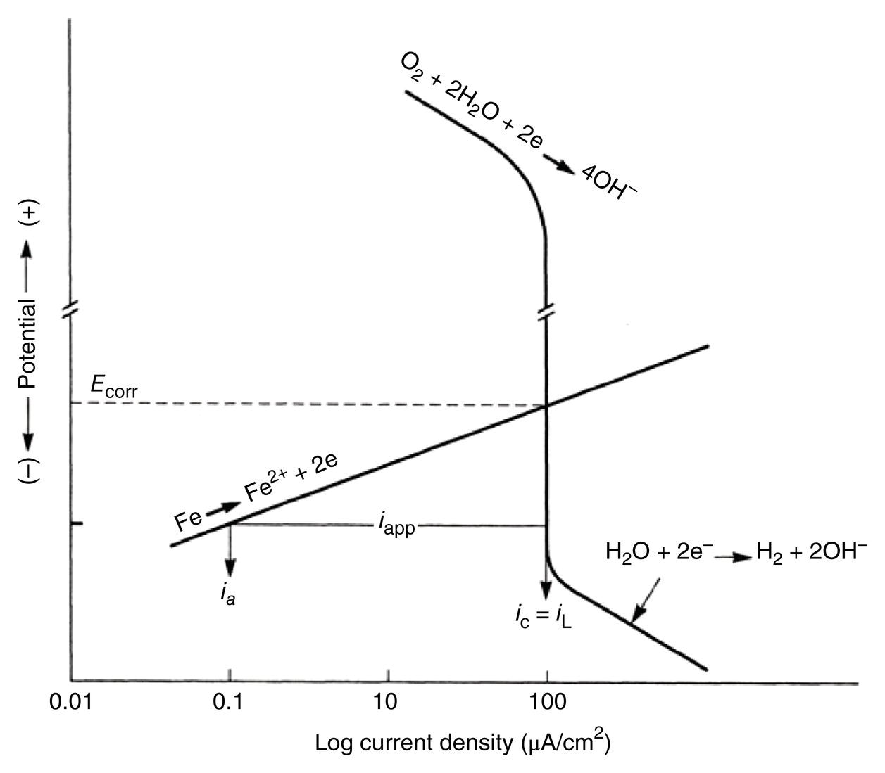


 ) of its local anodes. It is assumed that this is because at this potential, the anodic dissolution rate will equal the deposition rate, such that ia = iac = ioa. As in Figure 66.2, it can be seen that to reduce the corrosion rate from icorr to ia, the iron must be polarized for εc (potential change from Ecorr), which should be in the order of 0.1 V (CSE). This is the basis for the 100 mV shift, which is one of the three NACE1 criteria used as a guide for the reduction in corrosion and outlined in NACE SP0169-2013 [16].
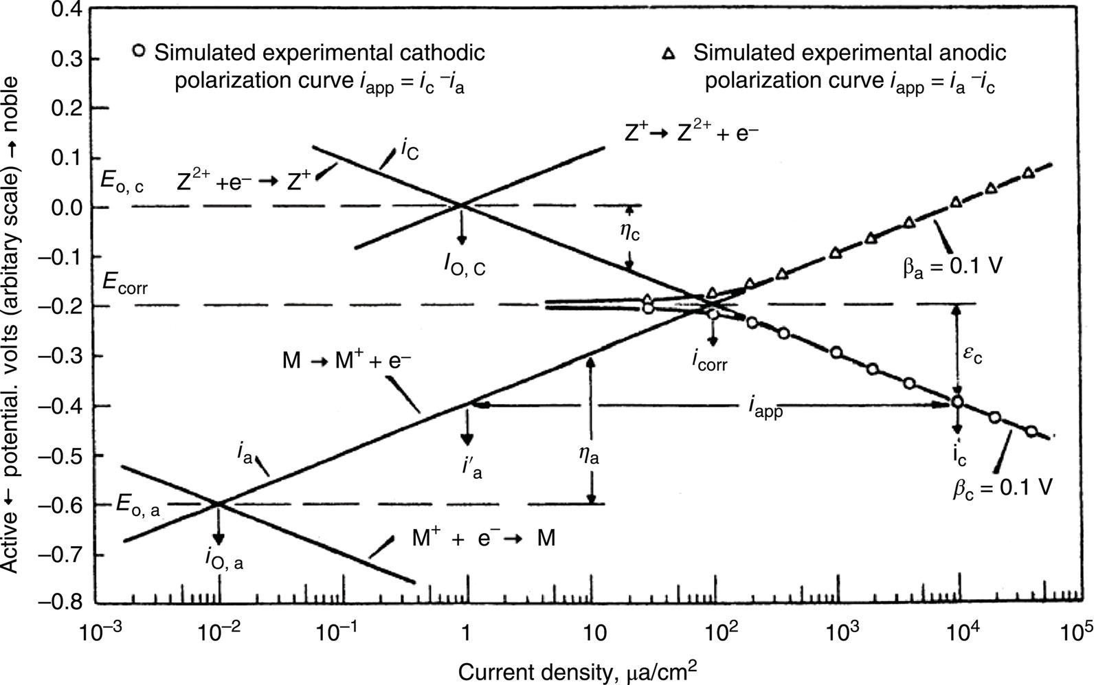
66.3.2 E–pH Pourbaix Diagram
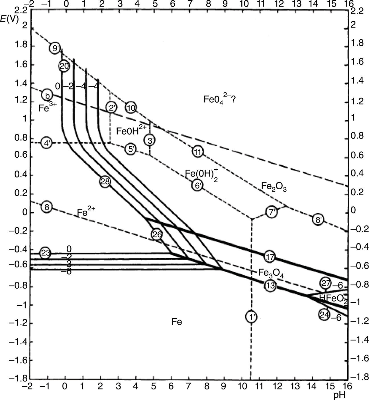
pH
Potential
Volt versus standard hydrogen electrode (SHE)
Volt versus copper-caturated CuSO4 electrode (CSE)
Below 10
E 0 = −0.62
E 0 = −0.94
Between 10 and 13
E 0 = −0.08 to 0.059 pH
E 0 = −0.40 to 0.059 pH
Above 13
E 0 = +0.31 to 0.088 pH
E 0 = −0.01 to 0.088 pH
66.4 How Cathodic Protection Is Applied
Metal
Voltsa
Magnesium
−2.38
Aluminum
−1.66
Zinc
−0.76
Iron
−0.44
Tin
−0.14
Lead
−0.13
Hydrogen
0.00
Copper
+0.34 to +0.52
Silver
+0.80
Platinum
+1.20
Gold
+1.42 to +1.68
66.4.1 Sacrificial Anode Cathodic Protection System
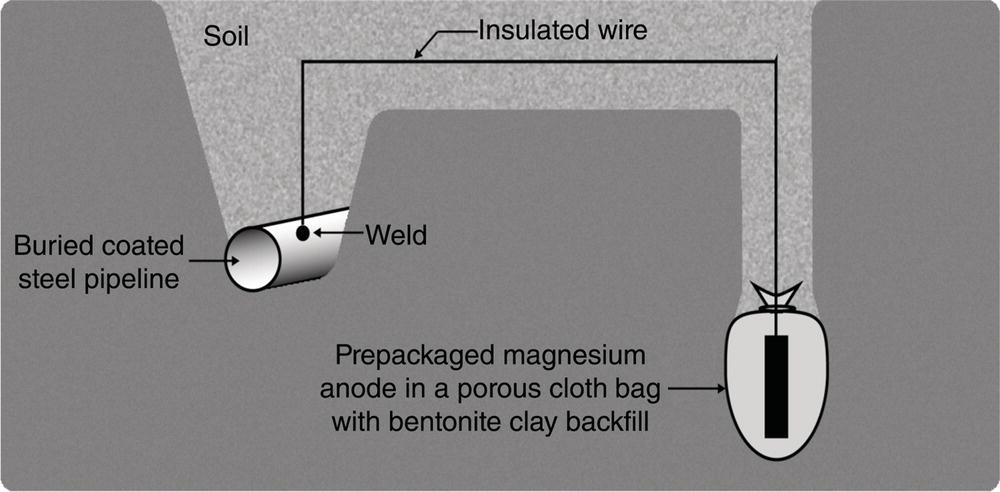
66.4.2 Sacrificial Anode Design

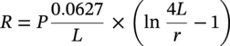
66.4.3 Anode Material
66.4.4 Impressed Current System
Alloy
Environment
Potential (Versus Cu/CuSO4) (V)
Practical Consumption Rate (kg/A—Year)
Magnesium
Soil
−1.50
8.5
Zinc
Seawater
−1.10
12
Zinc
Soil
−1.10
12
Aluminum alloys
Seawater
−1.10
3.5 (approximately)
Al–Zn–Hg
Aluminum alloys
Seawater
−1.15
3.7 (approximately)
Al–Zn–In
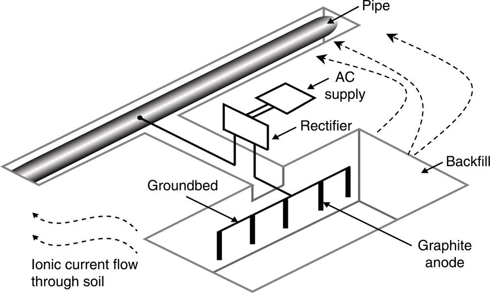
66.4.5 Sacrificial Anode Versus Impressed Current Systems
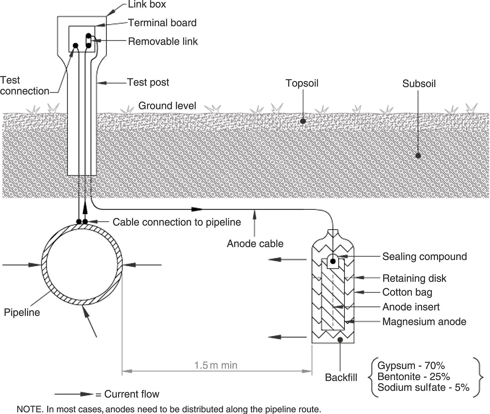
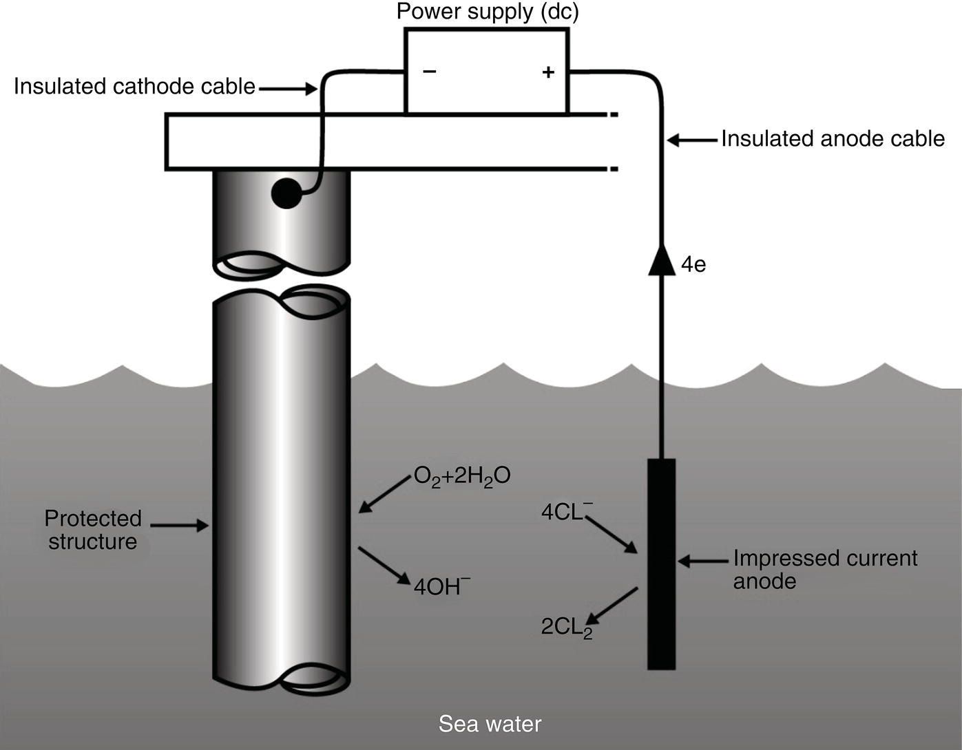
Sacrificial Anodes
Impressed Current System
66.5 Design Principles of Cathodic Protection
66.5.1 Current Requirement for a Cathodic Protection System
66.5.2 What Is the Most Economical Way for Supplying Current?
66.5.2.1 Sacrificial Anode Systems
66.5.2.2 Impressed Current Systems
66.5.3 How Is the Protective Current Distributed Over the Structure?
66.6 Protective Coatings and Cathodic Protection
Effective Coating Resistance (ohm for 1 average ft.2)
Current Required (A)
Bare pipe
500
10,000
14.91
25,000
5.96
50,000
2.98
100,000
1.49
500,000
0.29
1,000,000
0.15
5,000,000
0.03
Perfect coating
0.000058
66.6.1 Beneficial Effects of Cathodic Protection Used in Conjunction with Coatings
66.6.2 Adverse Effects of Cathodic Protection Used in Conjunction with Coatings
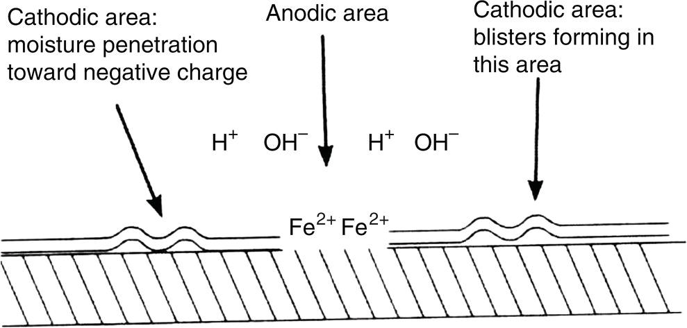
66.7 Monitoring Cathodic Protection Systems
66.7.1 Commissioning of Cathodic Protection System
66.7.2 Monitoring Test Stations (Test Points)
66.7.3 Annual Compliance Surveys
66.7.4 Direct Current Voltage Gradient Surveys—DCVG
Item
Type of Measurement
Time Schedule of Measurement
Impressed current test station
Check visually the T/R for any problems and measure the output voltage and current.
1–3 months
Impressed current test station
Carry out a function check of the impressed current station to make sure it is working adequately. This involves checking the T/R unit, permanent reference electrodes, groundbed, earthing system, and calibration of equipment used for measurements. Then, measure the output voltage and current.
1–3 years
Drainage station
Visually check the drainage point unit and then measure the drain point potential and current.
1 month
Drainage station
Carry out a detailed function check of the drainage station. Verify that the permanent reference electrodes are working. Measure the efficiency of the diodes and their protection devices. Check the setting of the resistors and check the calibration of instruments used. Measure the drain point potential and current.
Annually
Connections to foreign pipelines—resistive or direct bond
Measure the current flow. Carry out a detailed functional check of the device and measure the current flow.
Annually
Bonding devices and grounding systems
Measure the electrical continuity.
At least annually
Safety and protection devices that include AC decoupling devices
Measure the settings and function.
Annually
Permanent reference electrodes
Check validity of reference electrode by checking with a known standard reference electrode.
Annually
Test stations
Measure the (VOFF) OFF pipe-to-soil potential.a
Annually
Sacrificial anode stations
Check the sacrificial anode stations visually. Measure pipe-to-soil potential.
Annually
Sacrificial anode stations
Carry out a detailed inspection of the sacrificial anode station. Check resistor settings, efficiency of the bonding connection, verify that permanent reference electrodes are working properly and measure the pipe-to-soil potential.
3 years—but can be sooner if required
66.7.4.1 Applications of the DCVG Technique
66.7.4.2 DCVG Survey Requirements
66.7.4.3 DCVG Survey Technique
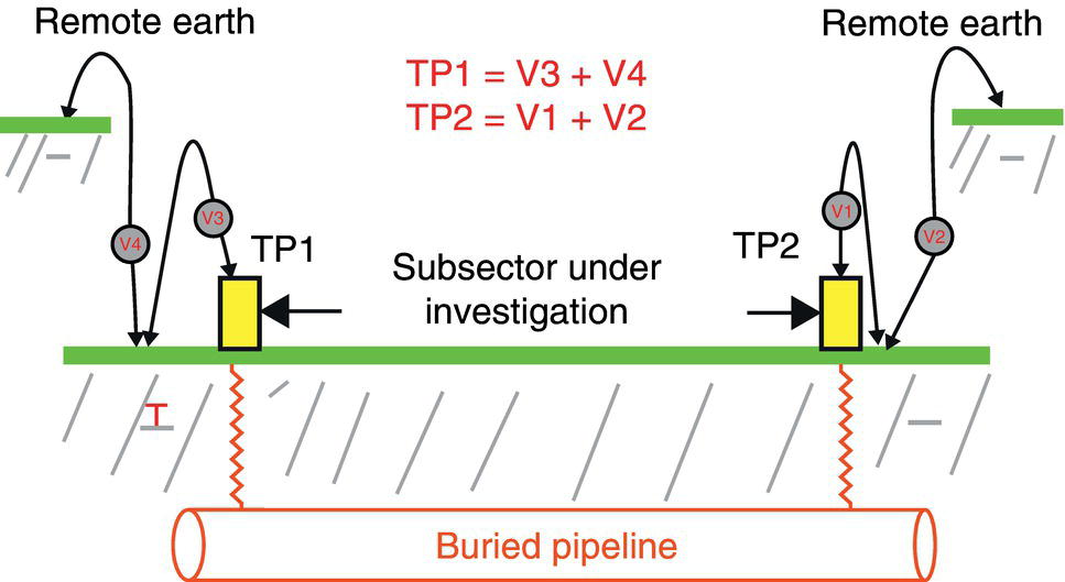
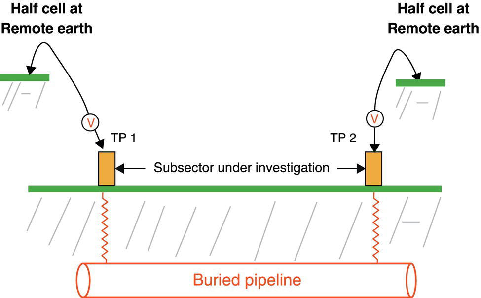

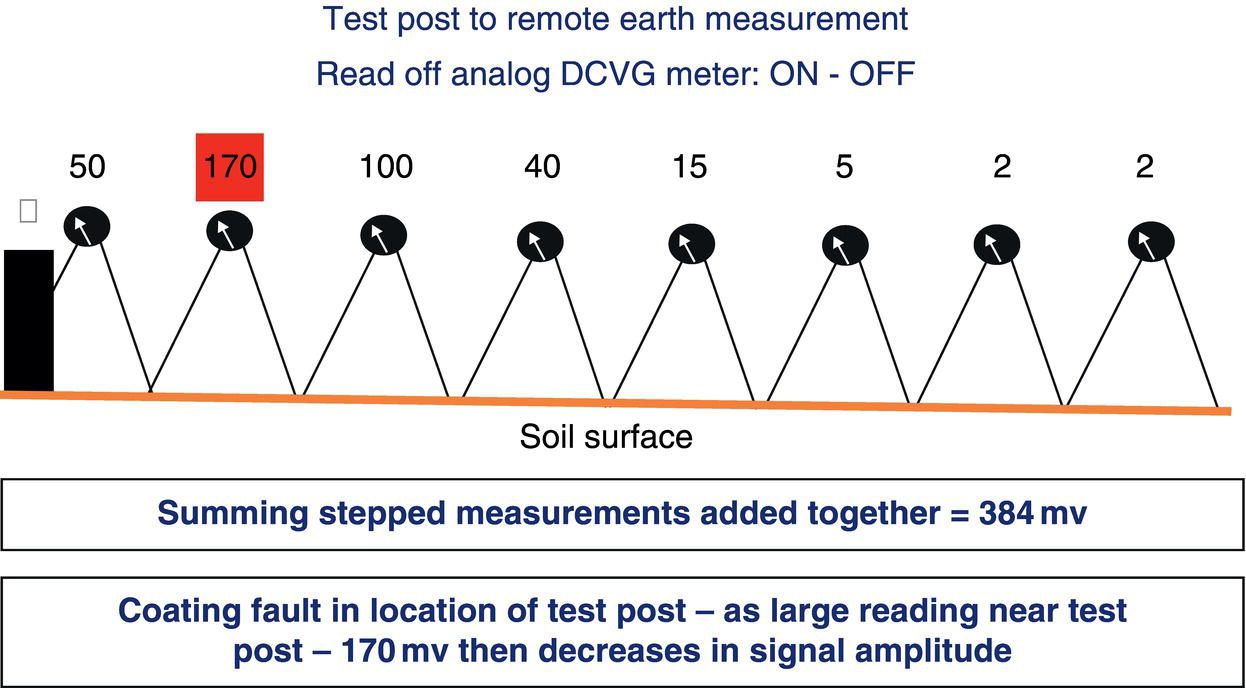
66.7.4.4 DCVG Electrical Measurements
57.5.3 Coating Fault Orientation
57.5.3.1 Overline to Remote Earth Measurement
57.5.3.2 Corrosion Status
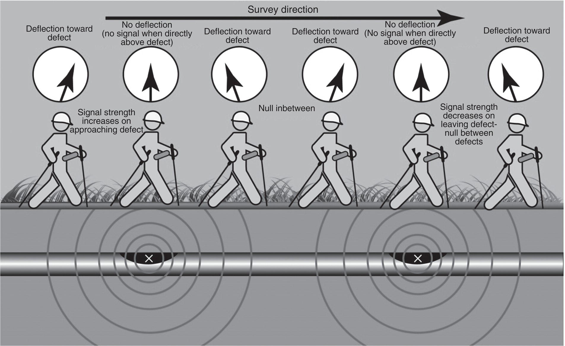
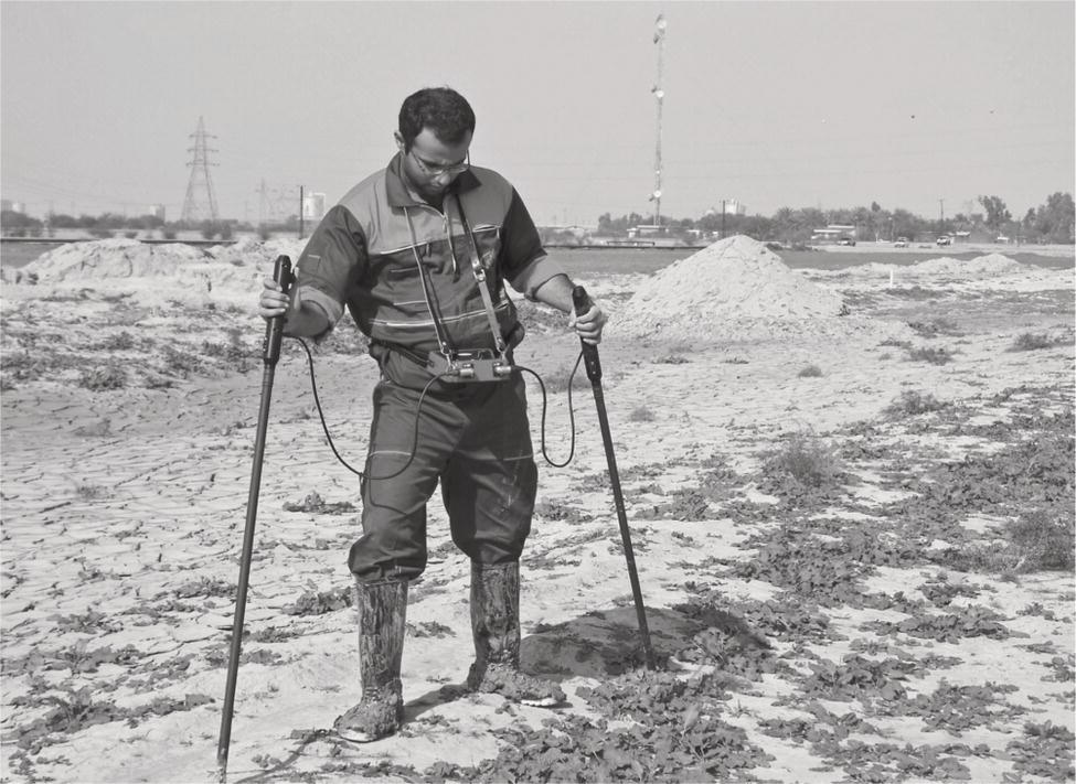
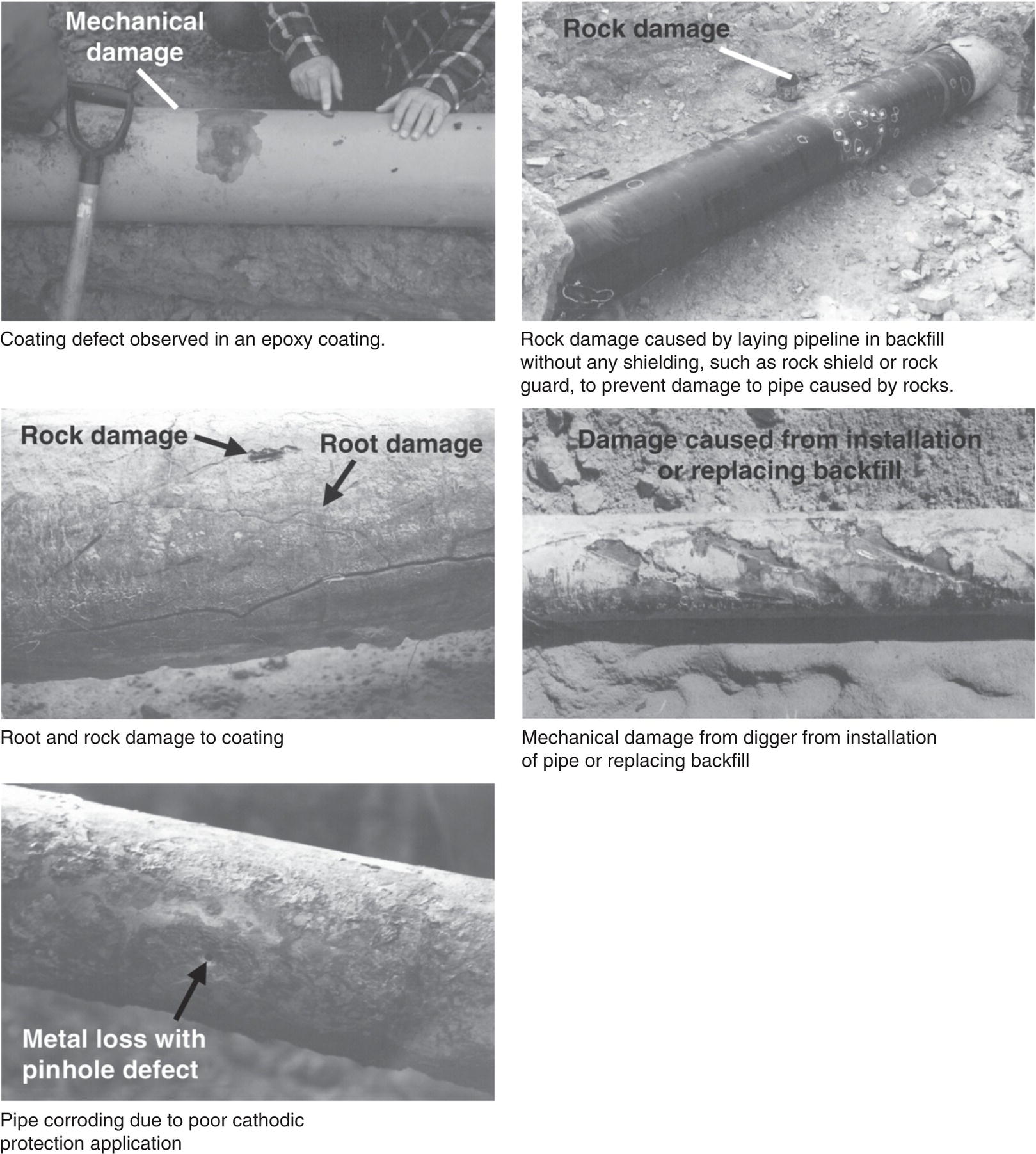
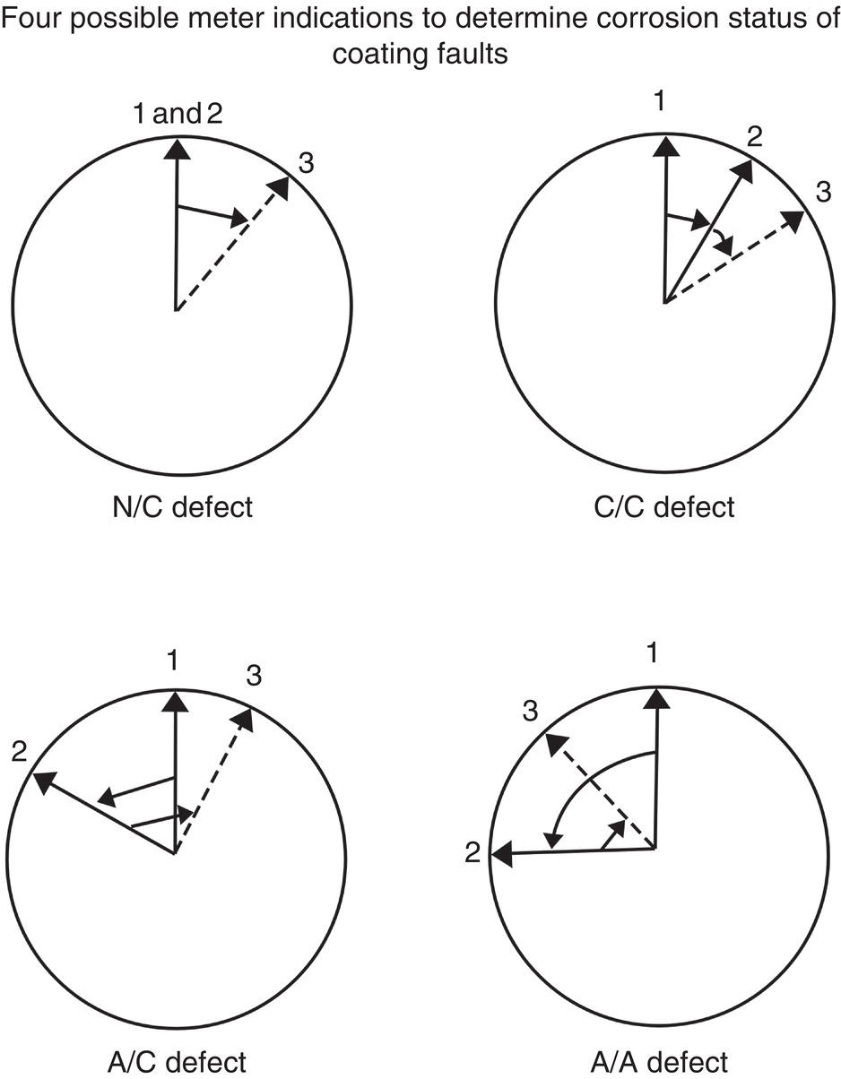
66.7.5 %IR Severity
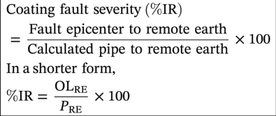
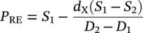

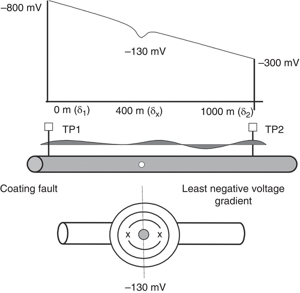
66.7.6 Coating Fault Grading
0–15% IR:
Characterized as small coating faults. Such coating faults can usually be left unrepaired provided the pipeline CP is good, and there are not too many small coating faults in close proximity.
15–35% IR:
Characterized as medium coating faults. These coating faults may need repair usually within normal maintenance activities.
35–70% IR:
Characterized as medium–large coating faults. These coating faults need to be excavated for inspection and repair to fix what could be considered a significant coating fault.
70–100% IR:
Characterized as large/important coating faults. These coating faults should be excavated early for inspection and repair.
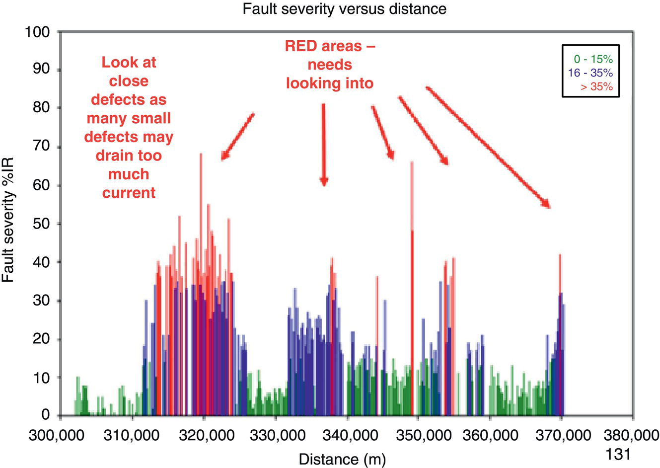
66.7.7 Close Interval Potential Surveys—CIPS/CIS
66.7.7.1 Close Interval Potential Surveys—CIPS/CIS Survey Technique

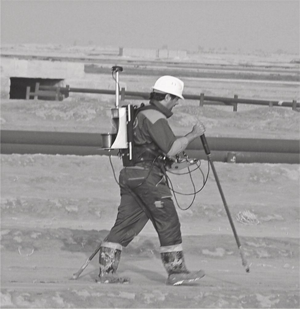
66.7.8 Soil Resistivity
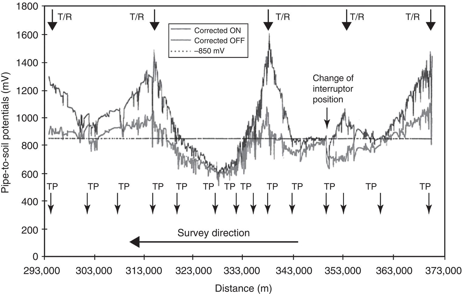
Resistivity Range (ohm-cm)
Steel Corrodibility
Years to Penetrate Sheet Steel
<500
Very severe
1–5
500–1000
Severe
5–10
1000–2000
Severe to moderate
10–15
2000–5000
Moderate to slight
15–20
5000–10,000
Slight
>20
10,000–1,000,000
Slight to none
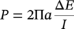
 is the soil resistance (ohms), from instrument reading;
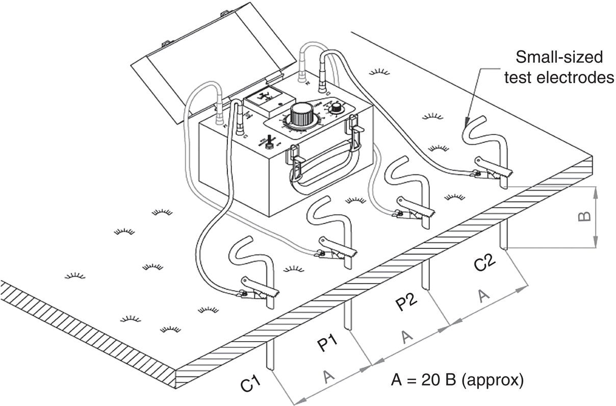
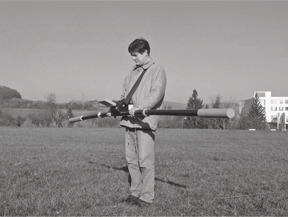
66.7.9 Corrosion Coupons
66.8 Cathodic Protection Criteria
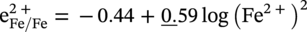
66.8.1 −850 mV Versus CSE with the Cathodic Protection Current Applied Criterion
66.8.1.1 Limitations of the −850 mV Potential to a CSE Reference Electrode with Cathodic Protection Applied Criterion
66.8.2 Polarized Potential of −850 mV Measured to a CSE Reference Electrode Criterion
66.8.2.1 Limitations of Polarized Potential of −850 mV Measured to a CSE Reference Electrode Criterion
66.8.3 100 mV Polarization Criterion
66.8.3.1 Applications of the 100 mV Polarization Criterion
66.8.3.2 Limitations of the 100 mV Polarization Criterion
66.8.4 Net Current Flow Criterion
66.8.4.1 Limitations of the Net Current Flow Criterion
66.8.5 Use of Criteria
Environmental Condition
Free Corrosion Potential Range (V)
Protection Potential (V)
Limiting Critical Potential (V)
Soils and waters in all conditions except those hereunder described
−0.65 to −0.40
−0.85
To prevent hydrogen embrittlement on high-strength nonalloyed and low-alloyed steels (>550 N mm2), the critical limit potential shall be documented experimentally
Soils and waters at 40 °C < T < 60 °C
–
For temperatures 40 °C ≤ T ≤ 60 °C then the protection potential may be interpolated linearly between the potential value determined for 40 °C (−0.65, −0.75, −0.85, or −0.95 V) and the potential value for 60 °C (−0.95 V)
Soils and waters at T > 60 °C
−0.8 to −0.50
−0.95
Soils and waters in aerobic conditions T < 40 °C with 100 < P < 1000 ohm-m
−0.50 to −0.30
−0.75
Soils and waters in aerobic conditions at T < 40 °C with P > 1000 ohm-m
−0.40 to −0.20
−0.65
Soils and waters in anaerobic conditions with sulfate-reducing bacteria activity
−0.80 to −0.65
−0.95
References
Note