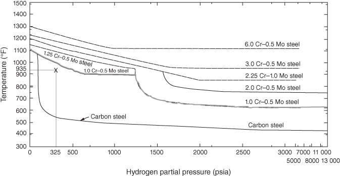
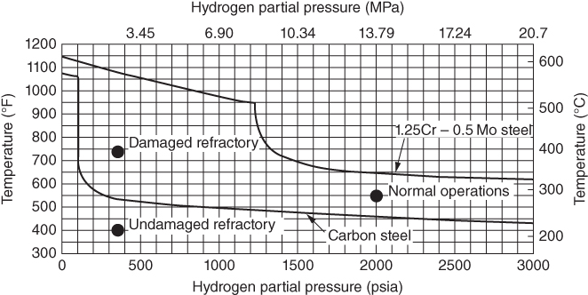
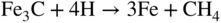
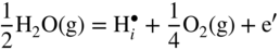
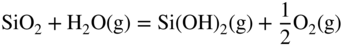
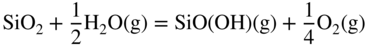
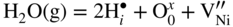
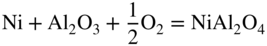
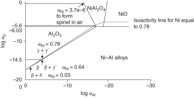
section epub:type=”chapter” role=”doc-chapter”> The lifetime of materials exposed to high temperatures is significantly decreased by high temperature oxidation, as it affects the mechanical properties of these materials. Several alloys, namely, Ni‐based superalloys are frequently used at high temperatures, due to their excellent mechanical properties and oxidation resistance. Depending on the temperatures required, different alloy classes are used. As high temperature oxidation takes place in an oxidizing environment, Ni‐based superalloy is a suitable choice of material, due to its capability to resist this type of corrosion, which stems from the formation of a slow‐growing, homogeneous, adherent, and low defect concentration oxide film. The atmosphere in which the materials are used is generally not dry, as there is always a certain amount of moisture in air, with the highest content of 100% reached in steam generators. The water vapor is known to affect the oxidation behavior of metals by increasing their oxidation rate. Therefore, the presence of water vapor may influence the oxidation behavior of Ni‐based superalloys at high temperature. It has been shown that steels oxidize faster in air or combustion gases containing water vapor, particularly in the case of low Cr‐containing steels. The presence of water vapor as reported in the literature to cause the cracking and spalling of oxides changes the transport processes in oxides and modifies the selective oxidation processes. The effect of water vapor on the oxidation behavior of metals and alloys at high temperature has been summarized in many reviews by Saunders et al. (2008). Hydrogen is also a gas that causes serious industrial problems, particularly in refinery vessels and other high temperature equipment, many times associated with water and/or water vapor (Alvorado 1995). Steels, carbon, and Cr–Mo steels, low‐alloy steels, and other materials can suffer hydrogen attack (HA) or hydrogen damage at high temperature, which results in rupture failures of steel components and/or microfissures in boiler tubes and other industries. The purpose of the current chapter is to provide a brief discussion of the corrosion reactions involving H2 and/or H2O, which are really an important subject of high temperature corrosion. Since the early ages of industrial usage of hydrogen, the selection of appropriate materials has been a concern for industrial gas operators. These operators have paid special attention to the issues raised by the specific interaction of this molecule with metallic materials, specifically with steel, in order to ensure safety and reliability of hydrogen from manufacture to cylinder filling, to distribution, and to usage at the customer site. Hydrogen energy development will face the same constraints of material compatibility, with even stricter requirements, as the equipment will be owned and partially operated by a wide range of nonspecifically trained users and will be operated at very high pressures, 700 bar or more. The phenomenon of internal hydrogen embrittlement due to excessive amounts of hydrogen introduced during the manufacture of steels has been known since the end of the nineteenth century. The phenomenon of internal hydrogen embrittlement when welding steels was discovered later. These two problems are now well mastered and are not covered here. This chapter only concerns the phenomenon of external hydrogen embrittlement caused by pressurized gaseous hydrogen in contact with steels, essentially at high temperatures. The hydrogen penetrates into the steel (during operation in the case of pressurized tanks) and diminishes local or overall mechanical properties of the steel. This can lead to bursting of these pressurized tanks under certain conditions. The hydrogen that penetrates into steels can be found either in metallic solution or in combined state (H2, CH4 molecules). When hydrogen is found in metallic solution, the phenomenon of steel deterioration is called gaseous hydrogen embrittlement; this phenomenon generally takes place at temperatures close to ambient, and the penetration or transport of the hydrogen takes place essentially by transport by dislocations when the material is undergoing deformation. This phenomenon therefore occurs essentially in areas with local plastic deformations. When hydrogen is present in a combined state, it is a matter of hydrogen attack (HA) or hydrogen damage. The hydrogen reacts with the carbon in the steel to form molecules of methane; this leads to the formation of microcavities in the steel and to a lack of carbon in the steel, which lead to a reduction in the overall strength of the material. Hydrogen is therefore transported by diffusion. This is why this phenomenon mainly takes place at high temperature. In addition, contrary to the phenomenon of hydrogen embrittlement, this phenomenon is reversible as long as microcavities have not formed. One of the most important parameters to be considered here is temperature; and, indeed, hydrogen embrittlement of steels mainly occurs around ambient temperature and tends to disappear at high temperature. On the contrary, HA only takes place at high temperature. Depending on whether the operating temperature is higher or lower than 300 °C, one or the other of the two phenomena mentioned above should be taken into account. In other words, HA is not to be confused with hydrogen embrittlement or other forms of low temperature hydrogen corrosion. Surface decarburization and internal decarburization are important effects of HA. Surface decarburization results in a decrease in hardness and increase in ductility of the material near the surface. This is usually only a minor concern for these types of application. However, internal decarburization, and in particular the formation of methane and consequent development of voids, can lead to substantial deterioration of mechanical properties due to loss of carbides and formation of voids and catastrophic failure. The main factors influencing HA are the hydrogen partial pressure, the temperature of the steel, and the duration of the exposure. Damage usually occurs after an incubation period, which can vary from a few hours to many years depending on the severity of the environment. High temperatures and low hydrogen partial pressures favor surface decarburization, while the opposite conditions (lower temperature, high hydrogen partial pressure) favor fissuring. In addition, the composition of the steel influences the resistance to HA; in particular elements that tie up carbon in stable precipitates, such as Cr, Mo, and V, are very important. Increasing content of such elements increases the resistance to HA, and Cr–Mo steels with more than 5% Cr, and austenitic stainless steels, are not susceptible to HA. Aside from Cr and Mo, other elements that tend to bind carbon in the form of stable metallic carbide, such as Ti, W, etc., have the same favorable effect. On the contrary, a high carbon content is detrimental. Similarly, the addition of Al, Ni, or excess of Mn has a detrimental effect on the behavior of welds. The residual elements that lead to the formation of nonmetallic inclusions have a detrimental effect. To prevent risks of HA, stress relief treatment at temperatures equal to or greater than 650 °C is needed. These types of treatment are covered by standards and/or should be carried out in accordance with the stipulations of the local code or the code of the manufacturer. It also appears that the risk of HA increases when the level of mechanical stresses increases. The hydrogen partial pressure should not be considered alone. Total pressure and additional stresses during operation or residual stresses, if not completely eliminated by heat treatment, should also be taken into account. In addition to the treatment following welding recommended above, it is better to limit the hardness of the weld bead and the heat affected zone. The operating limits for steels can be empirically described using the operating temperature and hydrogen partial pressure, as originally discussed by Nelson (1949) and in the American Petroleum Institute (API) recommended practice 941, “Steels for Hydrogen Service at Elevated Temperatures and Pressures in Petroleum Refineries and Petrochemical Plants” (Das 1996; Parthasarathy 1985). Since the 1970s, empirical data have been collected from operating plants and tests to establish operating limits of carbon steel and low‐alloy steel equipment in hydrogen service at elevated temperatures. API 941 provides guidance on those limits. Using API 941, if a piece of equipment or piping is operated above the API 941 Nelson curve, then the material is not suitable for service under those conditions. For example, if the normal operating conditions are a temperature of 488 °C (900 °F) and 2.23 MPa (323 psig) hydrogen partial pressure, as illustrated in Figure 12.1, then the carbon steel in this case and even the 1.0Cr–0.5Mo steel are not suitable for service under those conditions. There would be a risk of premature failure in a relatively short time of exposure. Either the temperature or the pressure would have to drop below the carbon steel curve, or chromium alloyed steel should be considered for use instead. The selection of a 1 1/4Cr–1/2Mo material would be the preferred choice. Figure 12.1 Illustration of API 941 Nelson curve – material selection for equipment exposed to hydrogen at elevated temperatures and pressures should follow API 941 guidelines. Using API 941, the following practices should be considered: For corrosion purposes, sometimes vessels are clad, lined, or weld overlaid to protect the vessel surface. This can provide initial protection, provided hydrogen does not diffuse through the liner or migrate behind the lining or cladding. If that occurs, then the vessel may be susceptible to HA. Refractory lining is often used to insulate a pipe or vessel to lower the metal wall temperature and is an effective way to reduce the effects of HA. However, the refractory can degrade, crack, or deteriorate due to operating conditions or even flexure of the refractory, allowing hot spots to form, which would elevate the metal wall temperature and possibly result in exceeding the HA operating limits of the equipment. Figure 12.2 illustrates how a degraded refractory hot spot could result in exceeding the operating temperature limit for a carbon steel line. Figure 12.2 Illustration of API 941 Nelson curve – damaged refractory can result in an increase in the metal temperature that, if above the recommended limits, could result in HA failure. One way to monitor the condition of the refractory is to perform regular infrared imaging of the equipment. For clad, lined, or overlaid equipment, the following practices should be considered: There is increasing concern that the Nelson curves may not be relevant for the newer steels being used in high temperature hydrogen service, or may be overly conservative, and there are increasing trends toward risk‐based inspection of items in hot hydrogen service. In this context, unsatisfactory service experience with the carbon–1/2Mo steel has led to consideration of the Nelson curves. Currently, API 941 warns against new construction with the alloy and urges inspection and monitoring of existing equipment. There are a number of inspection methods available. Most of them are based on ultrasonics: The overview of these techniques is given in Table 12.1. Table 12.1 Inspection methods to detect and quantify hydrogen attack In summary, in this section we have introduced the concept of HA and described the influence of various parameters on HA of materials, namely, steels. In order to safely use such materials in the presence of hydrogen, it is recommended to have an internal specification. This specification must cover: The two main sources of hydrogen that contribute to HA of steels in industries are from the corrosion of steel by boiler water in the waterwall tube for coal‐fired boilers and from high pressure, high temperature hydrogen‐containing atmospheres used in petroleum refining. HA problems related to these two separate areas are briefly discussed in Section 12.2.2. Subcritical drum boilers that use a recirculating steam‐generating system are prone to high temperature corrosion, particularly if the water chemistry is not properly controlled. Control requires (i) removal of impurities to purify the water and (ii) chemical treatments to control pH, electrochemical potential, and dissolved oxygen concentration. With adequate control, the waterwall steel tube forms a protective magnetite (Fe3O4) scale when steel is corroded by water under normal operating conditions (Cohen 1989): whose by‐product is hydrogen. Growth of magnetite follows a parabolic rate law with the scale growth rate diminishing with time. Accordingly, the generation of hydrogen likewise diminishes with time once a steady state is reached. The atomic hydrogen produced combines with other hydrogen atoms to form molecular hydrogen that is then dispersed in the boiler water as a gas or in solution. However, when water chemistry is poorly controlled, the boiler deposits formed on the surface of the waterwall tube may lead to acidic corrosion attack on the tube under the deposits, leading to large atomic hydrogen absorption by the steel. Hydrogen atoms in the steel then react with iron carbide (Fe3C) to form methane (CH4): Methane gas then accumulates at grain boundaries and other interfaces due to its low diffusivity. Microcracks and microfissures are eventually developed by increasing local gas pressure created by the increasing amount of methane gas produced by the iron carbide/hydrogen reaction. Furthermore, because of iron carbides being reduced to iron by reaction 12.2, the affected area is decarburized. The locations that are often susceptible to HA in the boiler are the burner zone and the bull nose area (Stultz and Kitto 1992). Monitoring and controlling boiler water chemistry is critical in preventing internal tube deposits and HA (Dooley 1987). HA is also a serious materials issue in the design and operation of refinery equipment, such as reactors in hydrotreating, reforming, and hydrocracking units. The mechanism for HA of steels in petroleum refining is essentially the same as that described in the waterwall tube that suffers HA in the boiler. As discussed earlier, adding Cr and/or Mo to the steel to increase the stability of iron carbides can increase the resistance of the steel in HA. But concerns have been raised as discussed by Parthasarathy (1985). Thus, Cr–Mo steels are much more resistant to HA than carbon and C–0.5Mo steels. The conditions under which carbon and Cr–Mo steels can be used in high temperature hydrogen service are described in detail in API 941 (Parthasarathy 1985). The behavior of carbon and Cr–Mo steels with respect to their resistance to HA is summarized in Nelson curves, as shown in Figures 12.1 and 12.2 (Chiba et al. 1985; Merrick and Ciuffreda 1982; Sorell and Humphries 1978; Turnbull 1995). Water is present in almost all environments where alloys and superalloys are used at elevated temperatures. Combustion of fossil and biofuels produces a high amount of water vapor. Steam is injected in stationery gas turbines to lower the flame temperature and is also formed during combustion. The presence of moisture in an oxidizing medium affects the oxidation behavior of metals at high temperatures. The effect of water vapor can be linked to the following processes: The kinetics during oxidation in the presence of water vapor is different of those obtained in dry air or oxygen, which is generally true, although the thermodynamic activity of oxygen is the same, as the dissociation of the water molecule is very stable. As parameters, such as grain size, grain boundary, and porosity of the oxide layer, which may be induced by the presence of water in the atmosphere, affect the mechanical properties of oxide scales, the understanding of the effects of steam on the oxidation resistance of alloys is important. In the case of high temperature materials, the effect of water vapor depends strongly on the nature of the formed protective scale, the exposure temperature, and water vapor pressure. Alumina‐forming materials are widely used at elevated temperatures; therefore, their interaction with water vapor is of technical importance in many fields, such as heterogeneous catalysis, corrosion, and microelectronics. The scale surface morphology and properties may be altered by the presence of moisture. It is therefore necessary to understand what effects parameters such as the amount of water vapor and the partial pressure have on the resistance of oxides particularly alumina scales (see also Section 7.7.2). It has been suggested that the presence of water vapor affects the oxidation behavior of metals; therefore, the morphology of the scales is also affected (Rahmel and Tobolski 1965). Depending on the type of metal, the oxidation is, in some cases, enhanced or does not change the oxidation rates of alloys compared with the oxidation in dry air. For example, iron oxidizes 1.6 times faster at 950 °C in H2/H2O and O2/H2O mixtures than in dry air. The oxidation rate of a MCrAlY coating is 25 times greater in H2/H2O than in dry air at 1080–1100 °C (Leyens et al. 1996). The growth rates of chromia formers are proved to be higher in moisture‐containing gases (Schütze et al. 2005; see also Section 7.7.2). However, water vapor has generally little effect on alumina‐forming alloys (Saunders et al. 2008). The oxidation rate of Fe–21.5Cr–5.6Al is even slightly decreased in wet air compared with dry air at 1000 °C, whereas the growth rate of PM 2000, a mechanical alloyed material, is slightly increased during isothermal oxidation. Moisture has little effect on the oxidation of commercial Ni‐based superalloys and coatings, as shown by Onal et al. (2003), but is detrimental for the scale adhesion. The presence of water vapor affects the selective oxidation of species responsible for the formation of a protective scale. Kvernes et al. (1977) reported a decrease in the duration of the initial oxidation stage with water content in the ambient gas and an increase in the subsequent reaction rate under the same conditions for the high temperature oxidation of Fe–13Cr–xAl alloys. Though thicker scales formed, they were also less protective, including spinel in the inner part of the scale. Buscail et al. (1997) found that the water vapor decreases the isothermal oxidation rate of Fe–Cr–Al at 1000 °C. Although the effect was not significant, the study proposed that the initial transient oxidation processes were affected by the wet conditions and that water vapor might have significant effects on the cyclic oxidation of certain alloys. It is well known that most technical steels oxidize faster in water vapor or in air or combustion gases containing water vapor than in dry air, but, according to Kofstad (1988), the mechanisms are not well understood. Therefore, it is important to know the composition and defect structure of the surface as they play an important role in the diffusion process. Anghel et al. (2004) found that upon addition of water to CO gas, the dissociation rate of CO on Cr decreased, and after subsequent removal of water, the dissociation rate increased again. In this case, the surface activity for CO dissociation should be a key factor for carbon uptake in certain applications and can be reduced by adsorbed water. These results suggest the following adsorption ranking: N2 < H2 < CO < H2O. Increased dissociation of oxygen (O2 → 2O) and complete dissociation of molecular water (H2O → 2H + O) on surfaces of metal–oxide promote an increased transport of both O and O2− in the oxide due to increased concentration gradient of O and O2− over the oxides (Hultquist 1997). Cation sites are Lewis acids and may interact with electron donor molecules, such as water that has a lone pair of electrons, while oxide ions may act as basic sites interacting with acceptor ions, such as proton to produce a hydroxyl group. Where selective oxidation occurs, oxygen may be added to the adsorbate, not as O2−, but as a neutral oxygen atom. There will be a corresponding reduction of the substrate in the form of electrons that might be free carriers, but more often this will lead to a localized decrease in the oxidation state of the metal at the surface. Hydrogen is a nonpolar molecule with low polarizability and has a weak donor or acceptor properties. Water has a large dipole moment and lone pair of electrons and is therefore a good donor. Adsorption occurs by acid–base process through interaction with metal ions; non‐dissociative molecular adsorption also occurs. Oxygen is a very powerful electron acceptor and can be reduced in several steps. Nitrogen and argon are generally inert, as expected. The presence of water in the oxidizing atmospheres causes the formation of various defects, such as pores and whiskers. Whiskers are generally formed on the surface at the end of a dislocation by diffusion through a hollow void (Raynaud and Rapp 1984). This process is possible due to faster dissociation of water compared to oxygen, which leads to surface reaction as rate determinant for their growth and therefore their linear kinetics; however, as the oxide thickens, diffusion becomes the rate‐controlling mechanism. Rahmel and Tobolski (1965) stated that pores occur at the iron/wustite interface during the oxidation of iron at 850 °C. In the presence of water vapor or carbon, a H2/H2O or CO/CO2 mixture is formed, respectively, in these pores, which transports oxygen to the iron surface by an oxidation/reduction mechanism. Therefore, oxide bridges are built upward, from the metal to the scale, which enables the further oxidation of the metal without substantial inhibition. For this mechanism to take place, water vapor should penetrate the scale, and this occurs through microcracks or by proton transport. The pores are generally formed at the scale/oxide interface due to vacancies coalescence, especially for scale growing by outward transport of cations. The enhanced plasticity (ability to creep), possibly due to the incorporation of hydrogen in the lattice observed by Tuck et al. (1969), allows the scale to maintain the contact with the substrate. Quadakkers et al. (2005) showed that the scale spallation of oxides formed on Fe/12–19% Cr in steam is accompanied by the formation of a rapidly growing magnetite layer and an inner scale consisting of Cr2–O3 precipitates in a FeO matrix, whereby the two layers are separated by a gap due to pores. Additionally, molecular gas transport occurs through the outer scale. As the overall scale thickness increases, the Fe activity at the scale/gas interface gradually decreases due to an increasingly difficult transport of Fe cations to the oxide surface due to the presence of the large gap that develops. The purity of the alloy and exposure temperature plays an important role as they determine how the vacancies coalesce within the scale and/or at the interface scale/metal to form pores. Porosity is observed at metal/scale interface during oxidation in dry air of chromia‐formed alloys, while the pores are distributed through the entire scale. The effect of water vapor on transport mechanisms within chromia scales is to increase cation vacancies, and thus chromium diffusion is enhanced, leading to vacancy condensation and pore formation. At the same time, however, there is an increase in inward diffusion of oxidant due to the effective diffusion of OH−, and Henry et al. (2000) suggest that the pores become incorporated in the growing scale. If wet gas is exchanged with dry gas during the oxidation, the scale remains permeable, indicating that water vapor is preferentially adsorbed in the internal surfaces, preventing further reaction with oxygen, as well as closure, as observed by Ehlers et al. (2006) during the oxidation of 9% Cr steels. Oxidation of metals in water vapor‐containing atmospheres at high temperature is accompanied by the formation of hydrogen defects, which are mainly dissolved protons (Norby 1993; Tveten et al. 1999). The reaction can be written as or As water reacts with oxygen to form hydroxyl ions, the following equation can be written: From this equation, it can be assumed that the concentration of dissolved proton depends on the activities of water as well as oxygen. Relatively large hydrogen concentrations may be dissolved in oxides doped with lower valence cations and with oxygen vacancies as the predominant native point defects. In this case, the interaction with water can be written as One can see from Eq. 12.6 that oxygen vacancies are gradually filled while protons dissolve in the oxide. The literature demonstrates that hydrogen dissolves as protons and is bound to the oxide ions to form the substitutional or considering the equilibrium of gases: Therefore, the incorporation of hydrogen protons in the oxide can be written as If this equation determines the dissolution, then the relationship with the partial pressure of water is given by At high p(H2O) or p(O2), protons may become the dominant defect, compensated by defect electrons, metal vacancies, oxygen interstitials, or acceptor dopants. It is generally agreed that the Grotthuss mechanism allows transport of “water” in oxide scales by a proton “hopping” process in which protons localized at oxide ions move by transfer from one oxygen atom to another. Since oxygen is available everywhere, the net effect of proton diffusion is diffusion of water, and since proton diffusion rates are high compared with metal or oxygen, diffusion of “water” is easy (Saunders et al. 2008). In close‐packed structures, such as alumina and chromia, the dissolution of molecular water is less favored as, for example, in silica. Metal oxides generally react with water to form hydroxides and oxyhydroxides, which are sometimes volatile. The volatilization of several metals was studied by Opila (2004). The reactions of the most important oxides with water vapor for protection of metals at high temperature, to form volatile species, are Volatilization generally induces an accelerated consumption of the scale‐forming metal and, therefore, its depletion in the substrate. The presence of water vapor is known to accelerate the degradation of chromia‐forming alloys (Schütze et al. 2005). Asteman et al. (2000) showed that fast oxidation of the stainless steel 304L in the presence of water vapor was due to lower Cr/Fe ratios in the scales and consequently more rapid diffusion, where the changes in the Cr/Fe ratios were essentially attributed to the volatilization of chromium. CrO2(OH)2 is the most stable species compared with CrO2(OH) (Johnson and Panas 2000). The influence of water vapor on the oxidation of alumina formers is not significant below 100 °C; however, the effect is much pronounced at 1400 °C, with Al(OH)3 as the most stable of aluminum hydroxides (Hashimoto 1992). Thus, the rates of evaporation increase in the following order: Al(OH)3 < Si(OH)4 < CrO2(OH)2 (Opila 2004). During the growth of oxide scales in the presence of water, the scale plasticity can change. The results reported by various studies are in contradiction; some workers found a decrease of oxides plasticity in the presence of water vapor, which induces spalling, whereas improvement of scale adhesion was observed as a result of increased plasticity by others. Through iron oxidation at 950 °C, Tuck et al. (1969) found that the scale thickening was accelerated with the introduction of moisture into the atmosphere. Their explanation was that water vapor, especially hydrogen, is incorporated into the lattice and prevents the loss of contact between the substrate and the scale, which is possible due to the increased plasticity (ability to creep) of the oxide in wet conditions, but not to the accelerated vacancy diffusion within the oxide. The water vapor (hydrogen) increases the concentration of dislocations and/or their sources and sinks or the mobility of already existing dislocations. Rounded and spalled edges were observed on Fe specimens (Rahmel and Tobolski 1965) cycled in wet air, suggesting a lowering of the oxide plasticity due to moisture. The degradation manifested first at the specimen edges, where plastic deformation and accommodation of the surface oxide are required during thermal cycling in order to avoid spallation. This was observed in comparison with dry air exposure where the oxide was sufficiently plastic to deform at the edges and maintain adherence to the substrate during cycling. Another result from this study (Atkinson 1985) was the rapid weight loss of oxide that was initiated much earlier in air containing water vapor. The source of atomic hydrogen at elevated temperatures can be from the rapid waterside corrosion at the internal diameter of the waterwall tubes in a coal‐fired boiler when water chemistry is not properly controlled and can also occur in some refinery equipment, such as reactors in hydrotreating, reforming, and hydrocracking units, which is exposed to a high temperature, high pressure hydrogen atmosphere. The atomic hydrogen reacts with iron carbide in the steel to form methane gas. Continued ingress of atomic hydrogen into the metal causes an increasing amount of methane gas to be generated and accumulated at grain boundaries and other interfaces, resulting in the formation of microcracks and microfissures in the steel. In addition, the steel is decarburized. Continued growth of damage and decarburization of steel result in its rupture. The water vapor addition to air affects the isothermal oxidation of the different alloys in different ways. Materials as alumina, for example, in these conditions, show a gross growth rate, and the observed mass gain may be due to the transformation of γ‐AlO(OH) to formation of metastable δ‐Al2O3, which is transformed gradually to α‐Al2O3 at higher temperatures as shown by the following sequence: The increased mass gain during oxidation in moisture can be due to faster dissociation of water compared to oxygen, which lead to surface reaction as rate determining for their growth and therefore to linear kinetics; however, as the oxide thickens, diffusion becomes the rate‐controlling mechanism, i.e. the kinetics should have been changed. There are also more defects in the oxides formed in wet air – especially pores. This may be due to the reaction of water with the oxide to form hydrogen defects (protons), which modifies the defect structure and therefore the formal nature of the defect (Douglass et al. 1996). The other explanation may be that the oxide microstructure change leads to different diffusion processes in the scale. The pores are observed in the scale and not at the former substrate surface that, if present, should induce scale spalling. The fast diffusion of species induces thicker scales. As the water vapor amount increases, the effects are more severe, especially for alloys on which a continuous alumina layer could not be formed. The formation of transient oxides can also be influenced by water vapor addition, as the transient oxide scale usually thickens with higher humidity. For instance, NiO growth could be faster than in dry air, as NiO is known to react with Al2O3 to form the spinel NiAl2O4 (Huang et al. 2006), and, as a result, the time dependence of different oxide formation may be affected. If hydrogen is incorporated as interstitial in NiO, which is a p‐type semiconductor with cation vacancies (Birks et al. 2006), the following defect reaction occurs: The equation shows that the vacancy concentration is increased, which could lead to an increase of NiO growth rate. Hultquist et al. (2001) suggest that an enhancement of metal cation transport in alumina‐forming materials, such as the alloy FeCrAlY, during high temperature oxidation can be achieved by adding hydrogen to the substrate, either by electrolysis of water or from the gas phase. Maris‐Sida (2004) showed that for longer times of cyclic exposure (up to 500 hours) in wet air (air + 0.1 atm water vapor) compared with dry air, the scale formed on CMSX 4 at 1100 °C is thicker and exhibits a multilayered structure containing an appreciable, dense, and continuous layer of α‐Al2O3 formed at the alloy surface at some early stage. This layer is maintained, while subsequent layers of NiAl2O4, Ni(Al, Cr)2O4, and NiO grow sequentially on top of the alumina. These results show that nickel may be diffusing through the alumina scale, although the possibility that these oxides formed initially as transient oxides cannot be ruled out. This increased NiO rate induces greater internal oxidation depths, which would increase the critical amount of aluminum required to form a continuous scale on the metal (Gesmundo and Viani 1986). Thus, the thicker transient oxide scale observed on several alloys and superalloys must be caused by the increased NiO and possibly chromium oxide growth rate. The accelerated oxygen transport in the presence of water vapor may be of significance too, as hydrogen can be easily incorporated into NiO and Cr2O3 – hence the faster diffusion of Ni and Cr ions through the scale, resulting in rise outward growth of their oxides. The formation of spinels is also influenced by the water vapor presence and content. The spinel formation and stability depends strongly on the activities of the alloying elements in the alloy as shown in Figure 12.3 for the Ni–Al–O system. If we consider the formation of a spinel on α‐Al2O3, which is on a Ni–Al alloy, the formation reaction can be written as follows: Figure 12.3 Schematic of Ni–Al–O stability diagram at 1000 °C with the activities of nickel indicated for various equilibria (Maris‐Sida 2004). This reaction could occur either at the α‐Al2O3/gas or at the α‐Al2O3/metal interface. As the oxygen pressure is very low at the oxide–metal interface, the Ni activity must be very high; in contrast, the Ni activities should be extremely low at the oxide–gas interface for the spinel to be formed. Sahin et al. (1992) suggested that Ni diffused through α‐Al2O3; hence, Maris‐Sida also proposed that the spinels are formed at the oxide–gas interface. Ni must diffuse through defects to reach the oxide–gas interface. It is established that the growth of α‐Al2O3 is controlled by the inward diffusion of oxygen through the oxide grain boundaries (Palladino and Kingery 1962). The proposed defects in α‐alumina are Schöttky defects (Kröger 1983) involving alumina vacancies
Chapter 12
Corrosion by Hydrogen and Water Vapor
12.1 Introduction
12.2 Corrosion by Hydrogen
12.2.1 Concept, Mechanism, Detection, and Prevention
Inspection method
Equipment required
Principle
Advantages
Limitations
Remarks
Ultrasonic echo attenuation method
Ultrasonic flaw detector or pulser/receiver and oscilloscope, longitudinal wave transducer
This technique measures the loss of back‐wall echo amplitudes as an indication of hydrogen damage
Low cost, simple to use
It has no ability to discriminate hydrogen attack from abnormal grain size, inclusions, laminar cracks, rough surfaces, internal surface geometry, cladding, disbondment between cladding and base metal
Not recommended as a stand‐alone method for detection of hydrogen attack
Amplitude‐based backscatter
Ultrasonic flaw detector or pulser/receiver and oscilloscope, longitudinal wave transducer
This technique measures the amplitude of backscattering signals and uses high backscattering amplitude as the indication of hydrogen damage
Low cost, simple to use
It cannot differentiate hydrogen attack from internal flaws such as laminar cracks and inclusions. The validity of the technique also depends on the surface condition of the calibration material under examination as well as on the pressure applied on the ultrasonic transducer
Not recommended as a stand‐alone method for detection of hydrogen attack
Velocity ratio
Ultrasonic flaw detector or pulser/receiver and oscilloscope, longitudinal and shear wave transducers
This technique measures the shear‐to‐longitudinal wave velocity ratio of the entire wall thickness to assess the extent of hydrogen damage
Low cost, relatively simple to use
Cladding materials influence the result. It cannot identify hydrogen damage less than 15% of the wall thickness
Not recommended as a stand‐alone method for detection of hydrogen attack
Creeping waves/time‐of‐flight measurement
Ultrasonic flaw detector or pulser/receiver and oscilloscope, creeping wave transducer
This technique measures the reduction of creeping wave velocity as the indication of hydrogen damage
Low cost, relatively simple to use
It is applicable only to partially damaged steel and only to thin‐walled vessels
Not recommended as a stand‐alone method for detection of hydrogen attack
Pitch‐catch mode shear wave velocity
Ultrasonic flaw detector or pulser/receiver and oscilloscope, set of shear wave transducers
The relative change in shear wave velocity is measured and correlated to the extent of hydrogen damage
Low cost, relatively simple to use
This technique cannot differentiate hydrogen attack from change of material thickness. Its sensitivity to hydrogen damage is low
Not recommended as a stand‐alone method for detection of hydrogen attack
Ultrasonic method based on backscatter and velocity ratio measurement
Ultrasonic flaw detector or pulser/receiver and oscilloscope, set of shear and longitudinal wave transducers
To detect suspect areas (areas affected by hydrogen attack), the backscatter technique is used. To confirm the findings of the backscattering measurement, the sound velocity measurement method is employed
Relatively simple to use and accurate method
Cannot be used to its full extent on clad and complicated geometry areas (see velocity ratio and scatter method limitations)
Recommended method for detection of hydrogen attack
AUBTs – advanced ultrasonic backscatter techniques
Ultrasonic flaw detector or pulser/receiver and oscilloscope, set of shear and longitudinal wave transducers, plotter
A pattern‐based backscattering technique is used as the initial screening method. Depending on the backscatter pattern observed, one of the several follow‐up techniques, including frequency‐dependent backscatter, direction‐dependent backscatter, velocity ratio, spectral analysis, and spatial averaging can be used to determine the cause of backscattering signal
Determines the distance of hydrogen attack progression, can be used to determine the material mechanical properties of the hydrogen‐damaged region
Requires some degree of skill in interpreting pulse‐echo patterns
Recommended method for detection of hydrogen attack
Method based on TOFD, thickness mapping, backscatter and velocity ratio
TOFD equipment, thickness mapping equipment
The backscatter technique is used as an initial scanning; then velocity technique and thickness mapping techniques are used to confirm and provide picture of the extend of the damage
Gives permanent record of test results. Relatively accurate
Requires some degree of skill in interpreting TOFD and pulse‐echo patterns
Recommended method for detection of hydrogen attack
In situ metallography replicas
Grinding disc, abrasive papers. Final cleaning chemicals and polishing suspensions. Acetate films, microscope
Detects microstructure changes in tested areas, degradation of material, microcracking and their causes (e.g. creep, hydrogen damage)
Can be carried out in situ. Gives permanent high‐resolution record. Relatively fast and cost effective
Requires high degree of skill in preparing and interpreting microstructure images. Sensitive to surface contamination. This technique samples small areas only, and it is not able to measure the depth of the damage
Recently, the replication microscopy technique has become an important non destructive evaluation (NDE) method for oil and power industry. Recommended method
12.2.2 Attack in Coal‐Fired Boilers and Petroleum Refining

12.3 Corrosion by Water Vapor
12.3.1 Kinetics and Mechanisms of Oxidation
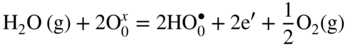
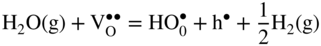
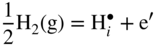
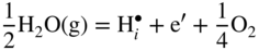
12.3.2 Protons Incorporation
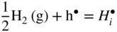
 that can be simply written as interstitial proton
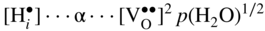
  . It has been demonstrated that the concentration of interstitial protons is increased with p(H2O) and decreasing temperature. Thus, the dissolution of protons in the oxide may be written as

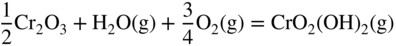
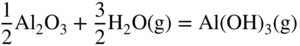
12.3.3 Volatility of Metal Hydroxides

12.3.4 Plasticity of Oxide Scales
12.4 Conclusions

 and oxygen vacancies
  . It is thus possible that Ni diffuses through these defects and reacts at the spinel/gas or at the NiAl2O4/Al2O3 interface. Ni2+ cation is slightly larger than Al3+ (
 and
and  ), and the largest interface in α‐alumina is 0.06 nm; it is, therefore, also possible that Ni can still diffuse through grain boundaries. Al is known to generally diffuse through grain boundaries in α‐Al2O3 (Toplygo and Clarke 1999). For example, at 1000 °C, the activity of NiO in α‐Al2O3 at the α‐Al2O3‐γ‐γ′ equilibrium is 4.3 × 10⁻¹⁰, whereas the activity of NiO in α‐Al2O3, as well as transport of nickel through α‐Al2O3, becomes more favorable as the metallic substrate becomes depleted of aluminum or, in other words, as the oxygen reaches levels sufficient to ionize nickel. The diffusion of the species can also occur through microcracks. The formation of the other spinels can also be explained by the same mechanism as proposed for the formation of NiAl2O4. Akhtar et al. (2006) proposed that a phase transformation occurs in nickel‐based single‐crystal superalloys (CMSX 4 and CMSX 10) as a result of the oxidation that creates the external NiO scale. This transformation, which is the precursor to internal oxidation, creates the β phase (NiAl) first followed by the δ phase (Ni2Al3) prior to the formation of the spinel Ni(Cr, Al)2O4 and Al2O3 in succession.
References
Further Reading
Corrosion by Hydrogen and Water Vapor
12.1
12.2
12.3
12.4
12.5
12.6
12.7
12.8
12.9
12.10
12.11
12.12
12.13
12.14
12.15
12.16