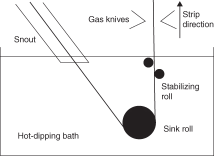
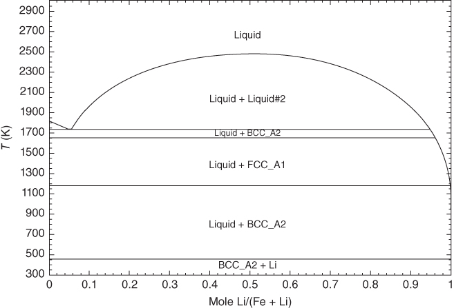
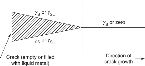
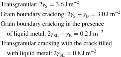
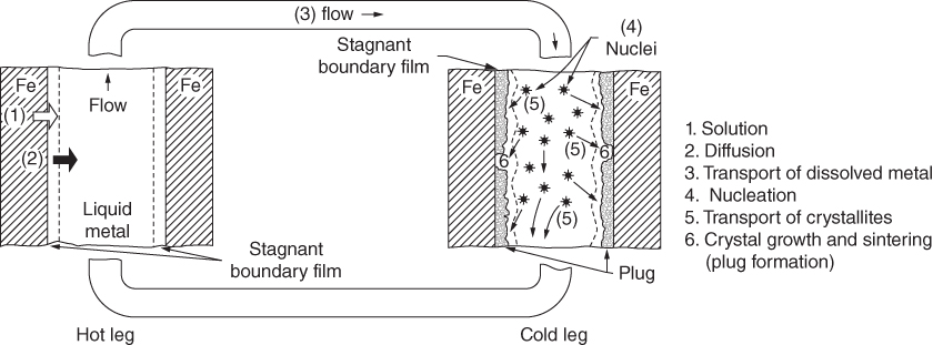
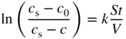
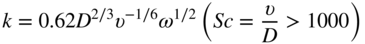
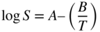
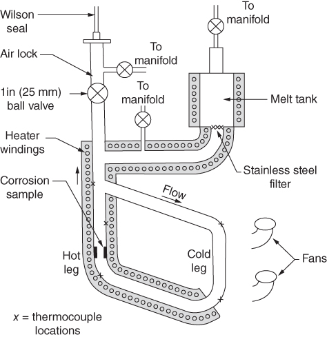
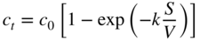
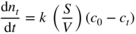
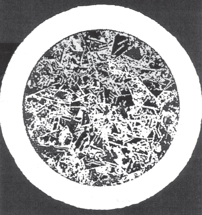
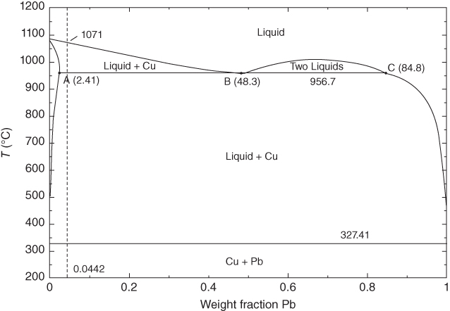
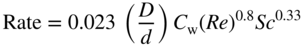
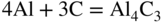
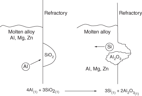
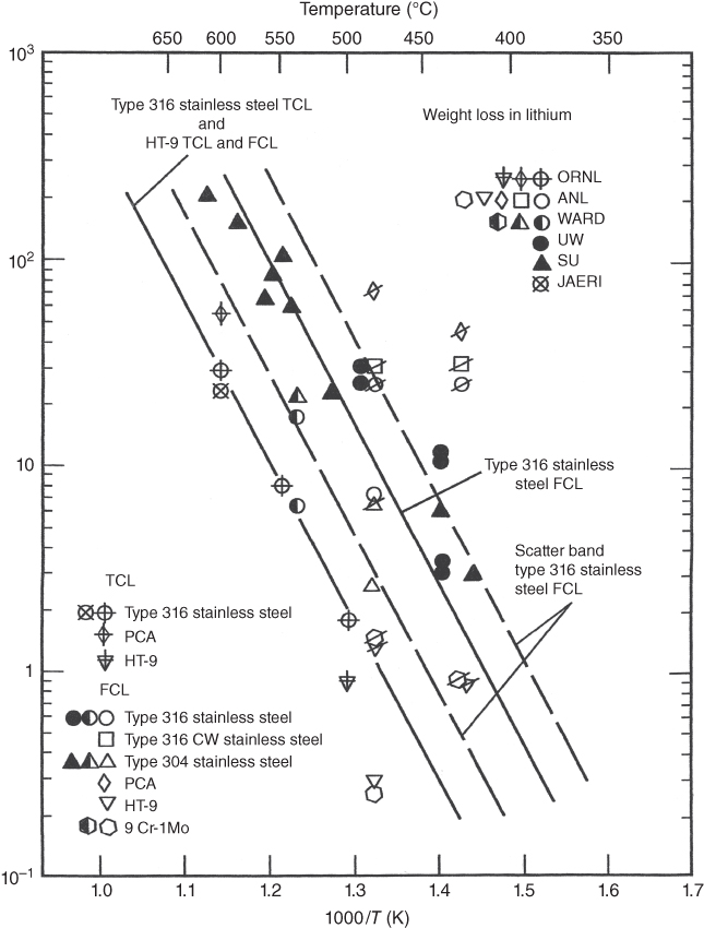
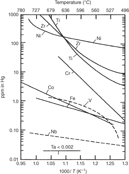
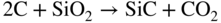
section epub:type=”chapter” role=”doc-chapter”> Molten metals, or liquid metals, are frequently used as heat transfer medium because of their excellent heat transfer properties. Due to their characteristics, namely, high thermal conductivity, high heat capacity, low vapor pressure, etc., most of their corrosion studies have been carried out in conjunction with nuclear reactor applications (Borgstedt 1982; Marchbanks et al. 1976), heat treatment baths, power generation, and others that the reader can find in articles and books listed in Further Reading. Sodium, for example, has been used as a coolant in fast breeder nuclear reactors. Molten aluminum is also one of the most aggressive metals to a number of metals and ceramics due to its engineering applications in die coating, containment materials, and semisolid processing (Tipping 2010). Molten aluminum can cause considerable corrosion of the handling and container materials, leading to an insufficient and, above all, unpredictable lifetime. In the aluminum industry, refractory performance against corrosion is an important factor affecting the quality of metal produced and the durability of furnace lining. The tolerance of aluminum alloy castings may be affected by the wear of dies caused by aluminum flow. The search for materials compatible with molten aluminum is of great importance in the service environment of semisolid processing of aluminum, where components are subject to complex stress conditions. Under such complex stress conditions, materials should possess not only enough erosion resistance but also high fatigue resistance, satisfactory creep strength, and toughness. Consequently, those materials usually used for containment of molten aluminum, such as graphite and aluminosilicate refractories, cannot be used, and few materials have been characterized and qualified (Yu et al. 1995). The coating of steel sheet by continuous hot dipping in a molten metal bath of zinc or in a Zn–Al melt is the most efficient and economical method of providing corrosion protection to most steel sheet compositions. Reliable performance of galvanizing pot hardware is essential to the productivity of a hot‐dip galvanizing line and the quality of coatings produced. As shown in Figure 14.1, the pot hardware in galvanizing bath includes the snout, sink roll, stabilizing rolls, and the bearings supporting them. The most frequent cause of galvanizing line stoppage is pot hardware problems that are related to one or more of the following three issues: (i) wear of bearings supporting the stabilizer roll and sink roll, (ii) corrosion of the pot hardware in molten Zn–Al bath, and (iii) the nucleation and growth of dross (intermetallic compound) on roll surfaces. Corrosion of the hardware by molten Zn–Al alloys is one of the most important reasons to cause downtime of production lines; thus the corrosion resistance becomes the primary criterion for the selection of pot hardware materials. Besides corrosion resistance, there are other properties required for pot hardware materials, among which the resistance to intermetallic dross buildup on the surface for roll materials, wear resistance for bearing materials, and ductility are the most important ones. Since corrosion resistance is the primary criterion for the pot hardware materials and each candidate material needs to show good corrosion resistance, usually corrosion studies of stainless steels and intermetallic materials are receiving further consideration (Seong et al. 2001). A significant industrial problem related with the handling of molten metals is their storage, even at relatively low temperature, because of their elevated corroding activity against metallic containers. For example, in the case of liquid aluminum, zinc, and tin, kettles are made of low carbon, low silicon steel and deep‐drawn in U‐form in order to avoid welding. However, total protection of the metallic container cannot be achieved, and the steel is heavily corroded, although the iron solubility in liquid Zn, Al, and Sn at temperatures close to their melting point is low because the abovementioned molten metals react with iron, forming several intermetallic compounds that precipitate in the molten bath. Figure 14.1 Sketch of a hot‐dip bath. By contrast, ceramics are rather inert under the same conditions. However, kettles entirely built of ceramics are very expensive due to their dimensions. In general, ceramics prevent heating of the molten metal as they are thermal insulators. For these reasons, instead of kettles, ceramic coatings on ferrous substances are often used. For the suitability assessment of ceramics or refractory materials for tools, crucibles, or handling aids in metallurgy and metals processing, e.g. for thixoforming or rheocasting, besides properties such as wetting behavior, wear resistance, thermal conductivity, and thermal shock resistance, mainly the corrosion behavior against the processed alloy influences the service life of a tool material. Therefore, testing strategies to characterize the corrosive interactions of ceramics with semisolid and molten metal alloys is receiving a lot of interest (Meyer‐Rau and Telle 2005). The corrosion behavior of metals, alloys, and ceramics in liquid metals is a complex problem involving simple dissolution (chemical corrosion), electron transfer processes (electrochemical corrosion), physical erosion (when there is a swift flow of melt relative to the surface of the solid), fouling, embrittlement, and stress corrosion, and this brief introduction shows that these phenomena have a real impact on many industrial applications. This chapter discusses several types of corrosion attack of materials by liquid metals and also examines reported interactions of important engineering materials with molten aluminum, zinc, lead, lithium, sodium, magnesium, mercury, and other metals. To define the destruction of a solid material by a liquid metal as corrosion, this word denotes solution and intermetallic compound formation, and the corrosion process for the most part simply depends on the solution rate and the extent of solubility of the solid material in the liquid metal. However, many complicating factors can influence the solution rate or the attainment of the solubility limit. The formations of surface intermetallic compounds and of oxide or nitride films are good examples of such factors. Other factors are impurities in the liquid metals (which may involve electron transfer processes, modifying or even overriding the simple dissolution process) and temperature gradients and multimetallic systems that can cause an increase in the amount of attack over that expected to saturate the liquid metal because of the mass transfer of material under the driving force of the temperature gradient or the concentration gradient. Several variables affecting liquid metal corrosion must be considered, and they are (i) temperature; (ii) temperature gradient; (iii) cyclic temperature fluctuation; (iv) surface area to volume ratio; (v) purity of liquid metal; (vi) flow velocity, or Reynolds number; (vii) surface condition of container material; (viii) number of materials in contact with the same liquid metal; and (ix) condition of the container material, such as the presence of a grain boundary precipitate, the presence of a second phase, the state of stress of the metal, and the grain size. These variables influence the observed corrosion process, and it is appropriate to discuss six types of corrosion attack that have been frequently reported in the open literature (Borgstedt 1982). The solubility of metals in molten metals and its variation have not been explained properly up to the present days. Stratchan and Harris (1956) and Kerridge (1961) noted that plotting the solubilities of metals (at.%) in a number of solvent metals showed a periodic variation with the solute and not the solvent, i.e. a given metal such as manganese showed a consistently high solubility in molten magnesium, tin, bismuth, and copper, compared with iron or chromium, and this variation was correlated with the solute lattice energy and hence the latent heat of fusion. In the more practical sense, dissolution may be uniform or localized. Preferential solution can take two forms: Figure 14.3 Fe–Li phase diagram. Figure 14.2 Energies involved in the growth of a crack. When this process is accompanied by stress, catastrophic failure can occur, a classical example being the action of mercury on brass. The situation may be described in terms of the surface‐energy changes when a crack propagates through a solid metal as shown in Figure 14.2 where γS is the solid–gas interfacial energy, γSL is the solid–liquid interfacial energy, and γB is the grain boundary energy. Tabulated below are the energy changes involved for different cracking modes, with numerical values for the case of copper in contact with liquid lead with a dihedral angle at a copper grain boundary of 90° and γS = 1.8 J m−2, γB = 0.6 J m−2, and γSL = 0.4 J m−2: It is seen that the presence of the liquid metal greatly lowers the surface‐energy change for grain boundary cracking (Rostoker et al. 1960). A good example of the even removal of metal from the surface to saturate the liquid metal can be that of a titanium specimen after being exposed to lead at 1000 °C for 40 hours. In the case of a complex alloy, the attack can also be a simple dissolution type as it can be shown by the corrosion of Type 304 low carbon stainless steel in sodium after 40 hours at 1000 °C. Another attack that might be termed simple dissolution is the decarburizing action of lithium and sodium, as it happens with Type 430 stainless steel after 40 hours at 1000 °C in lithium. If all the phase diagrams of liquid metal–solid metal systems were available, an ascertainment could be made of the depth of attack that would occur in a static system as a result of simple solution by examining the solubility limit of the solid metal in the liquid metal at the operating temperature. However, there would be no conception of the rate at which the solubility limit was achieved. Thus, upon looking at the Fe–Li phase diagram in Figure 14.3, it can be seen that the amount of attack of iron by lithium should be quite small in a static isothermal system, and corrosion tests have proved this. Therefore, in simple solution‐type attack, the amount of damage that the solid metal will receive depends on the ratio of surface area to volume of the system, but the rate at which the attack occurs can be greatly influenced by other variables, such as impurities in the system. Figure 14.5 Stages in thermal‐gradient mass transfer. It is well established that the dissolution of a solid metal in a liquid metal can be described by Eq. 14.2 (Dybkov 1990): where c is the concentration of the solute element in the melt, cs the saturation concentration, c0 the initial concentration of the solute, k the dissolution rate constant, S the solid metal surface, V the melt volume, and t the time. For a fixed volume of melt, when the dissolution proceeds, the concentrations of the elements rise, resulting in a decrease in the rate of further dissolution. When stirring is present in the melt, the dissolution rate constant, k, can be calculated by the equations below (Dybkov 1990): and Here ω is the angular rotating speed of the solid metal, ν the kinematic viscosity of melt, D the diffusion coefficient of the solute across the interfacial zone, and I = f (Sc). From the above equations it can be seen that the presence and intensity of agitation affect the dissolution rate of solids in liquid. Another important loss mechanism from agitation is that it may damage the protective layer or accelerate the wear by the detachment of the reaction product, such as protuberances. The effect of melt agitation is much more drastic for those materials that form thick reaction layers that do not adhere well to substrate and are not hard enough. Temperature is one of the most important variables affecting liquid metal corrosion, because the higher the temperature, the higher the solubility of the solid metal in the liquid phase. Also, as the temperature increases, diffusion rates increase, which is quite important in certain types of liquid metal corrosion, namely, simple dissolution. In general, the solubility, S, of a metal in molten metal varies with the temperature according to where A and B are constants for a given system. It is therefore possible for more material to dissolve from a container at its highest temperature end than at the low temperature end, and if the melt flows around the container by natural or forced convection, the liquid arriving at the cold region will be supersaturated and will precipitate solute until equilibrium is attained. If it is then recycled to the hot end, it dissolves more metal until saturated and then returns to the cold end to precipitate this excess. This thermal‐gradient mass transfer is illustrated in Figure 14.4, which shows a convection loop being circulated by a corrosive metal such as bismuth. Ward and Taylor (1957–1958) analyzed this process in some detail as shown in Figure 14.5. They found that the solution of solid copper in liquid lead and bismuth obeyed the following equations. Figure 14.4 Thermal‐convection loop. Under static conditions, at temperature T where ct = concentration of solute after time t, c0 = saturation concentration of solute, S = surface area of solid exposed to liquid of volume V, K = k0 exp. (−ΔE≠/RT) (ΔE≠ = activation energy for solution). Under flowing conditions If, therefore, the solute atoms can be prevented from entering the boundary film from the solid, the process will be halted. A method for doing this was discovered by workers at the US General Electric Company 60 years ago (Frost 1958). They found that small quantities of dissolved titanium, zirconium, chromium, nickel, and aluminum were effective as inhibitors of the corrosion of steels by hot mercury, the first two being particularly so. Later interest in the use of liquid bismuth as a carrier of uranium in a liquid metal‐fueled reactor led to the extension of the use of zirconium inhibitor to bismuth in steel circuits and to an elucidation of the inhibiting mechanism. The zirconium reacts with the nitrogen, which is always present in steel to the extent of about 100 ppm, to form a surface layer of ZrN, which is thermodynamically a very stable compound and is an effective diffusion barrier. Furthermore, as long as there is residual zirconium in solution in the bismuth (or mercury) and dissolved nitrogen in the steel, the film is self‐healing. Mercury boilers have operated successfully for thousands of hours relying on this principle. The cyclic temperature fluctuation is helpful in explaining erroneous static corrosion results since under a supposedly isothermal condition in a poorly controlled furnace, the liquid metal–solid metal interface temperature can fluctuate quite appreciably around a mean temperature. Thus, at the high temperature, material goes into solution and subsequently at the lower temperature comes out of solution and precipitates in the bulk liquid or forms dendrites or a uniform layer on the container wall. The Cu–Bi system is an example of this, at 500 ± 0.5 °C. Purity of the liquid metal can also have quite an effect on the rate at which the solubility limit is reached and can markedly affect the wetting tendency of the liquid metal on the solid metal. The next type of corrosion to be discussed is the alloying that occurs between liquid metals and solid metals. For this to result, there must be some solubility of the liquid metal in the solid metal. The Ag–Pb phase diagram (Figure 14.6) is an example of a system in which the liquid metal is soluble in the solid metal. In some experiments, the liquid metal dissolves considerably in the solid metal with the formation of an intermetallic compound. When vanadium is tested for 400 hours in lead at 1000 °C, an intermetallic compound is formed between the vanadium and lead. Figure 14.6 Ag–Pb phase diagram. When Type 446 stainless steel is tested in lead at 1000 °C, it is found that after 400 hours, lead has diffused into the alloy predominantly at the grain boundaries and has formed a compound. Sodium will penetrate solid copper at the grain boundaries and will form an intermetallic compound, which is considerably harder than the base metal, copper. One of the most serious types of corrosion that can occur is the deep intergranular penetration brought about by the removal of one constituent from an alloy. The best example of this is the selective removal of nickel from austenitic stainless steels, for example, a Type 347 stainless steel after 400 hours of testing in lead at 800 °C. Other examples of this type of corrosion are the attack on Type 304 low carbon stainless steel after 400 hours in lead and in lithium at 1000 °C. A considerable portion of the attack is attributed to the removal of nickel caused by the alloying of the nickel with the iron container wall, and it is assumed that the attack would have been less if the specimens and containers had been of the same material. The selective removal of nickel from a 75% Ni–25% Mo alloy also occurred in a sample from the hot leg of a thermal‐convection loop (TCL), which operated for 200 hours with lead at 800 °C and with a 300 °C temperature gradient. In this case, the nickel was preferentially removed from the hot zone and deposited in the cold zone of the loop. In liquid metals, impurities such as oxygen, nitrogen, and carbon can have an appreciable effect upon the rate of attack, and, in some cases, the whole mode of attack can be changed because of the effect of the impurity on the surface tension or because of the reactivity of the impurity. An example is the attack of stainless steels by lithium when nitrogen is the principal contaminant. However, the lithium is contaminated with a small quantity of nitrogen, the complete tube wall, comprising 0.89 mm, will be penetrated by the lithium during the same type of test (Casteels 1984). This is due to the nitrogen‐contaminated lithium reacting with the carbides that form the grain boundary network, since a test in Type 316 stainless steel with lithium that was contaminated with nitrogen resulted in shallow attack when the testing temperature was above the solution temperature of the carbides. The true effect of nitrogen on corrosion by lithium is not understood. High temperature alloys can be severely carburized by liquid metals, especially sodium and lithium, if the liquid metals have been stored under kerosene or have acquired carbonaceous material from some other source. In corrosion by sodium, oxygen impurities can have an appreciable effect on the rate at which the solubility limit is attained (Thorley and Tyzack 1967). In lead, the oxygen contamination, if any, decreases the rate of corrosion since most of the constituents of high temperature alloys can reduce the lead oxide and form a film that will act as a diffusion barrier between the solid metal and the liquid. The solubility of carbon in sodium has been measured; it is considered lower than the corresponding value for oxygen (2 ppm of carbon at 520 °C) but is sufficiently high to give rise to undesirable effects. Carburization of refractory metals and of austenitic stainless steels has been observed in sodium contaminated with carbon, e.g. oil, grease, or a low‐alloy ferritic steel, the source of which can be either decomposed organic material, e.g. oil or a ferritic steel of low‐ or zero‐alloy content. The latter is an example of chemical‐gradient transfer against the temperature gradient since the activity of carbon in Fe–18Cr–12Ni, possibly stabilized with titanium or niobium, is clearly lower than that in a plain carbon steel and there is, therefore, a driving force for carbon transfer. A deterioration in properties of both steels occurs, the austenitic becoming embrittlement and the ferritic softened. The effect can be minimized if the carbon activity in the ferritic steel is reduced to that in the stainless steel by the incorporation in the steel of a “carbon stabilizer” such as titanium. Hot trapping with zirconium removes carbon as well as residual oxygen, but generally carbon sources should be kept from liquid metal circuits containing materials sensitive to carburization effects. In summary, for the transfer of a nonmetal along an activity gradient (chemical gradient), chemical thermodynamics is a useful guide to probable behavior. The transfer of a nonmetal, X, dissolved in a molten metal, M′, to another metal, M″, will depend on the relative free energies of formation of M′X and M″X. Thus, sodium will give up oxygen to Zr, Nb, Ti, and U, as the free energy of oxide formation of these metals is greater than that for sodium; on the other hand, sodium will remove oxygen from oxides of Fe, Mo, and Cu unless double oxides are formed. Impurity reactions can be controlled or eliminated by adequate purification of the liquid metals, and in pumped loop systems, this can be achieved by using techniques known as cold trapping or hot trapping. Cold trapping involves taking a small percentage of the main loop flow and bypassing it through a container that is cooled to the required temperature to precipitate out the impurities. Hot trapping, on the other hand, involves removal of impurities by chemical reaction between the soluble species and a material that has a higher thermodynamic affinity for the impurity than the liquid metal or its containment. In certain systems where metal solubilities are relatively high (e.g. Ni in liquid lithium), the use of cold traps can encourage thermal‐gradient mass transfer; consequently, under these circumstances, other methods of purification may be required. Figure 14.7 Plug from a Type 446 stainless steel thermal‐convection loop that operated for 200 hours at 800 °C with a temperature gradient of 200 °C. These crystals were primarily alpha iron. Figure 14.8 Cu–Pb phase diagram. The most damaging type of liquid metal corrosion is temperature‐gradient mass transfer. The even removal of a slight amount of a container wall will not adversely affect its load‐carrying abilities; however, the collection of this material in the colder regions of heat exchanger tubes as dendritic crystals would cause a cessation of flow. An example of mass‐transferred material is seen in Figure 14.7, which is a plug from a Type 446 stainless steel TCL that operated 200 hours at 800 °C with a temperature gradient of 200 °C. These crystals were primarily alpha iron. Note that a plug is a precipitate that eventually blocks the pipe to liquid flow. Another example is the massive matte of mass transfer material that can be observed as a plug from an Inconel‐lead TCL that operated for 125 hours at 800 °C. In some loop experiments the crystals do not grow from nuclei in the bulk liquid, but mass‐transferred material nucleates on the wall, and the crystals grow out into the stream as revealed by iron crystals formed on a Type 410 stainless steel TCL after 40 hours at 1000 °C with lithium. The driving force for temperature‐gradient mass transfer is the difference in the solubility of the dissolved metal in the liquid metal at the temperature extremes of the heat transfer system. In examining the Cu–Pb phase diagram (Figure 14.8), it can be seen that there is considerable solubility of copper in lead at 900 °C, whereas at 500 °C it is much lower. Thus, by examining the phase diagram, the driving force for this phenomenon can be determined, but no information concerning the rate of the process can be determined. If there is selective removal of one element from an alloy, these atoms must diffuse to the surface and then go into solution. The atoms must then diffuse through the lamellar layer into the bulk liquid stream and are finally carried to the cold portion of the system where supersaturation will occur. A collection of such atoms can accumulate and form a nucleus that will grow to a stable size and then drop from the liquid. On the other hand, the atom may supersaturate close to the wall, diffuse through the lamellar layer, and then nucleate on the metallic wall and form a dendritic crystal, or it may diffuse into the wall. As yet, the rate‐controlling step in temperature‐gradient mass transfer has not been found. To obtain more data on mass transfer in liquid lead, a series of quartz TCL were operated at Oak Ridge National Laboratory (ORNL) with various alloys and the elements comprising the alloys. Results of these tests have indicated that the rate‐controlling step for mass transfer by lead at the velocities used in the TCL takes place in the hot leg and is probably a solution step. For example, it was found that the formation of an intermetallic compound, or other type of diffusion barrier, in the hot zone greatly increases the time that elapses before a plug occurs in the loop. In diffusion‐controlled mass transfer situations involving turbulent fluids, Epstein (1957) has suggested that mass transfer equations can be derived from heat transfer analogies and expressions relating corrosion rate to the dimensionless groups. Reynolds number (Re) and Schmidt number (Sc) have been found to have some application where corrosion rates are sensitive to changes in flow velocity or diffusivity in the liquid phase. The equation suggested by Epstein to meet this situation is of the form in which Cw is the concentration of the dissolved species at the wall, D is the liquid‐phase diffusivity for the soluble species, and d is the pipework diameter. The velocity term is incorporated in the Re number expression. The last type of liquid metal corrosion to be discussed is dissimilar‐metal mass transfer or concentration‐gradient mass transfer. One of the best examples that have been reported in the open literature is the interalloying between molybdenum and nickel. In this case, the molybdenum sample was being tested in sodium contained in a nickel crucible, and after 100 hours at 1000 °C, a sufficient quantity of nickel had transferred through the sodium and deposited and alloyed on the molybdenum surface to produce the Ni–Mo intermetallic compound and solid solution. Another example of this phenomenon resulted in the course of testing silicon with lithium in an iron capsule. It was shown that all the silicon has gone into solution in the lithium and has been carried to the wall of the iron container where alloying of the iron with the silicon occurred. Dissimilar‐metal transfer can cause many misleading results as can be seen by the difference in the depth of corrosion when Type 304 stainless steel was tested with lithium in two types of containers. In one case, the Type 304 stainless steel specimen was placed in a Type 304 stainless steel container, and the attack was rather shallow. In the second case, the Type 304 stainless steel was tested in an iron container, and the attack was much more severe, which was caused by the selective removal of nickel that was transported to the iron wall where it alloyed. In this case, atoms of metal A go into solution and move to the surface of metal B either by diffusion or by movement of the liquid. When they reach the surface of metal B, they come out of solution, alloy with metal B, and diffuse inward. The driving force for dissimilar‐metal transfer is the decrease in the free energy that is achieved through the alloying of the two metals. The greater the difference in the chemical potentials of A and B in the two solid phases, the greater will be the driving force for the occurrence of mass transfer. The rate of mass transfer is dependent on the temperature since an increase in temperature will, of course, increase the diffusion rate in both the liquid and the solid phases. A high solubility of metal A in B, or B in A, or both, will also facilitate mass transfer. A last example is given by Covington and Woolf (1961), who have investigated, among other systems, aluminum and molybdenum in molten lead, tin, and bismuth. In bismuth, three of the four intermetallic compounds were identified in the layer on the molybdenum in the following order from the molybdenum surface: Al3Mo, Al5Mo, and Al12Mo. In tin, only Al3Mo was observed, while in lead two compounds were formed, the controlling process probably being the rate of diffusion through the layers of the different compounds and the rate of solution of the more soluble metal (aluminum) in the liquid metal. In Section 14.2, the various types of liquid metal corrosion have been explained, and examples have been given; the driving forces for the various types of liquid metal corrosion have been discussed. Liquid metal corrosion has been described as mainly the solution of the solid metal in the liquid metal. The rate‐controlling step for the various types of liquid metal corrosion has not been determined. For the successful containment of the liquid metals, the amounts of impurities, such as oxygen, nitrogen, and carbon, should be carefully controlled. Future work in the field of liquid metal corrosion must be directed toward increasing the understanding of the rate‐controlling steps of dissimilar‐metal transfer and temperature‐gradient mass transfer. When this has been accomplished, corrective measures can then be taken to keep these types of corrosion to a minimum. In this section, we will examine interactions of engineering materials with some molten metals. The durability of metals and ceramics in molten aluminum is a great concern in engineering applications such as die casting, containment of liquid metals, and semisolid processing. Chemical corrosion and physical erosion are the main mechanisms of materials failure in molten aluminum. Chemical corrosion refers to penetration by the melt as well as the formation of interphase layers, prevailing when relative motion between the solid materials and the melt is negligible. Erosion is dominant when there is a swift flow of melt relative to the surface of the solid and becomes more severe when there are hard particles in the melt, where mechanical wear occurs on the material surface. Interactions of metallic materials with molten aluminum possess some common features. They all form intermediate layers of intermetallic compounds between the metal substrates and molten aluminum. These layers usually consist of either one phase or several phases, depending on the composition of the substrate and the reaction conditions. If different phases are formed, the zone consists of successive layers of intermetallic compounds. The layer adjacent to the substrate contains the highest content of the base element of the substrate, while the layer next to the molten aluminum is always aluminum rich. However, the corrosion or erosion rate in molten aluminum varies from metal to metal. Major metallic materials investigated are ferrous, nickel, and titanium alloys. Most of the dies for production of aluminum components in the casting industry are made of ferrous alloys, especially alloy steels. Various morphologies of the intermetallic compounds, formed between the ferrous substrate and molten aluminum, have been reported. It is believed that the different morphologies, porosities, and thicknesses of the intermetallic layers are associated with alloy additions and melt agitation. Intermetallic layers are significantly harder than the steel substrate. For example, the microhardness of a layer of 18C–8Ni stainless steel (in pure Al) is 1.8 ± 0.2 GPa (Dybkov 1990), and that of a nonporous layer of FeAl3 type (in liquid A380 alloy) is 1096 GPa (1 GPa ≈ 100 kg mm−2) (Sundqvist and Hogmark 1993; Yan and Fan 2000). The high hardness of interfacial layers is beneficial to wear resistance. However, the intermetallic layers on ferrous alloys do not provide good protection for the substrate. Due to the dissolution of iron and loss of interfacial compounds, the erosion rates of ferrous alloys in liquid aluminum alloys are usually high. The attack is further intensified when any relative motion exists between the solid ferrous alloy and molten aluminum. Nickel has been characterized as active with both liquid and solid aluminum (Yan et al. 1999). The high loss rates of nickel‐based alloys are primarily due to the high solubility of nickel in liquid aluminum. The solubility of nickel at different temperatures is given in Table 14.1, compared with that of other metallic elements. Moreover, penetration of molten aluminum into the depth of nickel‐based alloys can cause alloy loss in blocks (Yan et al. 1999). The high reactivity of nickel with molten aluminum is used in the production of alumina‐reinforced aluminum matrix composites. Nickel plating of the alumina phase overcomes the non‐wetting. In stainless steel, nickel preferentially dissolves in liquid aluminum from the intermediate zone (Dybkov 1990). Titanium is the least soluble in liquid aluminum among the elements listed in Table 14.1. The low solubility makes the liquid layer surrounding the solid titanium more readily saturated with titanium solute. The saturation inhibits the further dissolution of titanium. However, the high hardness of titanium makes it advantageous in the erosion environment. The growth of the intermediate layer between solid titanium and pure molten aluminum is controlled by the diffusion rate. Additions of alloying elements, such as Si, Mg, Ge, Cu, Li, Sb, Fe, Mn, Ti, Zr, and Ni, into liquid aluminum suppress the growth of the intermediate layer. Among them silicon is the most effective element, while nickel has the least effect (Takemoto and Okamoto 1988). Other metallic alloys investigated in terms of corrosion or dissolution in molten aluminum include Cr, Mo, Nb, and Y. The solubility of Cr, Mo, and Nb in liquid aluminum is relatively high, but Nb has a much lower solubility than Cr and Mo. For the Al–Y system, the solubility of yttrium in molten aluminum is found to be drastically affected by impurities in yttrium matrix and the occurrence of intermetallic phase at the Al–Y interface (Tunca et al. 1990). Table 14.1 Solubility of elements in pure liquid aluminum A Nb‐based alloy (Nb–30Ti–20W) is selected for fabrication of components like barrel and screw in a patented equipment for semisolid Al‐alloy processing. This alloy is found to be the best and superior to Ti alloys in resisting erosion by molten aluminum. The substantially reduced erosion rate is connected with the low solubility of niobium in molten aluminum and the high bulk hardness of the alloy (HV600). Extremely high corrosion rates of iron‐, nickel‐, and cobalt‐based alloys in molten aluminum are illustrated by the laboratory test results shown in Table 14.2 (Berry 1971). Samples of carbon steel and iron‐ and nickel‐based alloys were consumed in four hours at 760 °C. Cobalt‐based alloys, which appeared to be better than iron‐ and nickel‐based alloys, were corroding at rates too high to be considered for containment materials. In addition, titanium, although exhibiting a corrosion rate lower than iron‐, nickel‐, and cobalt‐based alloys, should not be considered for use as a containment material because of its rapid corrosion rate. Table 14.2 Results of static immersion tests in molten aluminum at 760 °C for four hours (Berry 1971) aSample was consumed. The corrosion resistance and mechanical properties of ceramics are affected by the chemical compositions and processing conditions, such as firing temperature and pressing pressure. To avoid infiltration by aluminum, the ceramic should be free of porosity and any constituent component that is prone to dissolve in molten aluminum. It is noteworthy that the reactivity of ceramics with molten metals other than aluminum cannot be used as indicators of their chemical reactivity with molten aluminum due to different phase relationships. For example, Si3N4 is found to be prone to degradation in ferrous alloy, but as will be discussed later, it is quite inert in aluminum (Yeomans and Page 1990). So far, ceramics that have been characterized chemically inert in liquid aluminum include graphite, aluminosilicate refractories, AlN, Si3N4, Al2O3, and sialons. The carbide Al4C3 is the only intermediate compound reported in the Al–C system (Qiu and Metselaar 1994) through the following reaction: The result of Al4C3 solubility in molten aluminum in the temperature range of 950–1000 °C calculated by Qiu and Metselaar (1994), and extrapolated to the lower temperature range below 700 °C, which normally applies in semisolid processing of aluminum, shows that the solubility of Al4C3 is extremely low. As one of the most cost‐effective material, graphite has been well known for its compatibility with aluminum melt and the case of fabrication. However, its brittleness makes it impossible for the fabrication of components where stress bearing is a requirement. Aluminosilicate refractories are well known for their applications in melting and holding furnaces. It is generally believed that molten aluminum alloys attack aluminosilicate refractories by redox reactions in which silica and silicates in the refractory are reduced to form elemental silicon while metallic aluminum forms aluminum oxide. The rate of attack is known to be proportional to the silica content in the refractory and especially that of the matrix phase. The mechanism of attack depends on the transport of elemental species and also on the redox reaction. While aluminum and alloying elements diffuse into the refractory, silicon is released by the redox reaction and counterdiffuses into the molten alloy (Figure 14.9). As a result, a reaction layer containing alumina is present after an incubation period and acts as a barrier against further melt penetration. Figure 14.9 Schematic diagram showing the mechanisms of molten aluminum alloy attack on a silica‐containing refractory. Alloy is lost by penetration and reaction with the refractory, while silicon is released into the alloy. Source: O’Brien and Akinc (1989). Reproduced with permission from John Wiley & Sons. As a high temperature structural ceramic and hard refractory material, AIN is a candidate refractory container for molten metals. It possesses an intrinsic inertness and a high hardness. However, during the processing of AlN by Al in vacuum at 1220–1280 °C, it is found to occur with a relatively high activation energy, suggesting a chemical interaction between AlN and aluminum. It reveals that the inertness of AlN in molten aluminum may need some conditions, and a reducing atmosphere is favorable. Al2O3 is one of the most widely applied crucible materials. It is not wetted by molten aluminum below 1000 °C and considered to be inert in molten iron and nickel. Si3N4 has been considered to be corrosion resistant in aluminum. Sialons are generally synthesized through sintering at high temperature above 1600 °C in nitrogen atmosphere. The main raw materials are Si3N4 and Al2O3. Al2O3 is an intermediate glass former capable of forming a network with silica and other network formers. This binding phase surrounding Si3N4 grains can be either glassy silicate or crystalline phases, or a mixture of both, depending on the composition and the cooling rate. The special network makes the sialon matrix more difficult to disrupt physically and more chemically stable, and this has been largely observed. In molten aluminum, SiC, B4C, TiCx, Cr2O3, etc. are active and corrode at relatively high rate. SiC can react with molten aluminum, producing Al4C3 and silicon, according to the following reaction (Viala et al. 1993): Silicon produced through the above reaction dissolves in aluminum, giving rise to an Al–Si alloy. Viala et al. systematically investigated the chemical interaction of SiC with molten aluminum. It is found that from 657 to 827 °C, α‐SiC interacts with aluminum via a dissolution–precipitation process. This mechanism involves the migration of carbon atoms from places where the SiC surface is in direct contact with the aluminum to the growing faces of Al4C3 crystals located at or close to the aluminum–SiC interface. The decomposition rate greatly depends on the polarity of the SiC surface exposed to aluminum. It is found that the interaction between SiC and aluminum alloy intensifies when introducing 3–7% Si into aluminum. B4C has a high hardness just below that of diamond, has excellent thermal stability, and is considered to have significant chemical inertness. However, it has been observed that B4C can react not only with liquid aluminum but even with solid aluminum (Viala et al. 1997). Carbon and boron atoms can diffuse into liquid aluminum from the surface of B4C. In the temperature range of 660 (melting point of aluminum) to 868 °C, the reaction products of Al–B4C mixture are Al3BC and AlB2, which are the same as those observed through reaction of solid B4C and solid aluminum. Above 868 ± 4 °C AlB2 is replaced by Al3B48C2, while Al3BC remains stable. A continuous layer of Al3BC, once formed, may constitute an efficient diffusion barrier and provide protection for B4C. In Viala et al.’s work (1990), a quasi‐protective reaction occurs at 812 ± 15 °C between TiCx (x < 0.9) and liquid aluminum: Through this reaction, TiC3 is decomposed by aluminum. Cr2O3 is also not inert with aluminum; in fact, it is observed to be attacked by aluminum alloys at temperatures even below 750 °C. Further research on the attack mechanisms of TiC3 and Cr2O3, as well as of other metals and ceramics in molten aluminum, has been conducted nowadays. Hot‐dip zinc‐coated steel production has increased dramatically over the past decade due to its relative economic benefits over other corrosion‐resistant materials. As a result of this increased demand, the need for greater manufacturing efficiency in the galvanizing process has also gained prominence. Numerous projects have investigated the molten metal corrosion aspects of materials and designs used for the submerged pot rolls and other hardware of continuous sheet galvanizing operations. The degradation and frequent failure of these structures results in significant production downtime and leads to high maintenance costs due to extensive repair and replacement. In order to prolong the service life of these rolls, many studies have attempted to obtain a better understanding of the corrosion behavior of the hardware materials in a variety of compositional coating baths. However, the test conditions and focus of each of the projects have been quite broad, encompassing ferrous alloys, cobalt alloys, coatings, and weld materials. Concurrently, extensive research has been carried out to define the equilibrium phase diagrams relevant to galvanizing applications. Advanced zinc phase diagrams involving Al, Fe, Cr, Ni, Co, and others are concurrently being formulated. However, with this array of research focused on materials for continuous galvanizing pot rolls, minimal effort has been directed toward understanding the molten metal reactions of hardware and containment kettles employed in general (batch) galvanizing, which uses zinc possessing very low levels of aluminum and, hence, vastly different corrosion properties. To enrich our knowledge of these issues, corrosion tests of 316L stainless steel, 410 stainless steel, 1015 carbon steel, Fe3Al, FeCrSi, and other alloys have been conducted in pure zinc bath and zinc–aluminum baths (Liu et al. 2005; Xu et al. 2007). It was found that, in general, both metallurgical composition and lattice structure played important roles in the molten metal corrosion behavior of these alloys. High contents of nickel combined with the influence of chromium improved the resistance to molten zinc corrosion. An increased bath temperature played an important role in molten metal corrosion by accelerating the dissolution process and changing the nature of intermetallic layers. A small amount of aluminum reduces the corrosion rate by reducing the activity of Zn in the Zn–Al baths and forming an inhibition layer. However, after aluminum content reaches the critical point, the dominant corrosion process changes from Zn–Fe reaction to Al–Fe reaction, and, therefore, the corrosion process is accelerated by increasing aluminum content in the bath. The results of static tests in molten zinc for selected iron‐, nickel‐, and cobalt‐based alloys are summarized in Table 14.3. Nickel‐based alloys suffered the worst attack, followed by austenitic stainless steels, Fe–Ni–Cr alloys, and Fe–Cr alloys. Cobalt‐based alloys generally performed better. However, an Fe–Ni–Co–Cr alloy (556 alloy) performed as well as cobalt‐based alloys. Table 14.3 Results of static immersion tests in molten zinc at 455 °C for 50 hours (Lai 2007) aComplete alloying. Table 14.4 Corrosion of several iron–nickel–chromium and nickel‐based alloys in liquid sodium at 1000 °C (Borgstedt et al. 1989) Lead melts at 327 °C. Nickel and nickel‐based alloys generally have poor resistance to molten lead corrosion. The solubility of nickel in molten lead is higher than that of iron‐casting steels, and stainless steels are commonly used for handling molten lead. For example, cast iron centrifugal pumps are used to pump liquid lead. The compatibility of steels with liquid lead and liquid lead–bismuth is a critical issue for the development of accelerator‐driven system. Fazio et al. (2001) carried out a set of tests in stagnant molten lead and lead–bismuth at several temperatures. Two tested martensitic steels (mod. F82H and MANET II) underwent oxidation phenomena at the higher testing temperature (476 °C), due to oxygen dissolved in the melts. At a lower test temperature (300 °C) and higher exposure time (5000 hours), the oxidation rate of the martensitic steels studied seemed to be lower, and the developed oxide layer protective against liquid metal corrosion. The tested austenitic steel (573 K), in turn, exhibited an acceptable resistance to corrosion/oxidation under the test conditions. Li (2002) examined the thermodynamic basis for controlling oxygen level in lead–bismuth eutectic systems to prevent steel corrosion and coolant contamination. By using mixtures of H2 and H2O (steam) to obtain low oxygen partial pressure (<10−24 atm or around 10−6 wt% in lead–bismuth), and calculating the potential signals of one type of oxygen sensors with a solid electrolyte and molten bismuth reference electrode, they obtained results that provide the guidance to implement the oxygen control technique in a nuclear energy system. This is an interesting application of solid‐state electrochemistry to high temperature nuclear technology. One important and perhaps unique feature of corrosion in the alkali metals is the formation of corrosion products based on complex ternary oxides. For example, oxides of the type (Na2O)2 FeO can form when iron is corroded in sodium under conditions where the standard state binary oxides FeO, Fe2O3, and Fe3O4 are thermodynamically unstable. It has also been shown that many transition metals form complex oxides with Na2O and corrosion products based on the ternary oxide Na3NbO4 have been identified on the surfaces of niobium after exposure to the sodium containing oxygen (Thorley and Tyzack 1973). This type of oxide is mechanically unstable in flowing sodium environments, and therefore it is relatively easy to promote fresh surfaces for further attack by oxygen impurities. Complex oxides of the type NaCrO2 also feature in the corrosion of stainless steels in alkali metals. NaCrO2, for example, may exist either as an oxide film on the surface of the steel during the initial stages of corrosion, or it may, under more adverse conditions, penetrate the grain boundaries and become a precursor for grain detachment. In cold‐trapped sodium containing only a few ppm of oxide, refractory metals such as Nb, V, Ta, and Zr can suffer severe oxidation. Their behavior is much the same as in oxidizing gases at high temperature, forming nonadherent oxide films. Oxygen can also diffuse into the metal to produce solid solutions with consequent embrittlement. To prevent this occurrence, the oxygen level in the sodium is brought down below the ppm level with a “hot trap.” Nitrogen is virtually insoluble in pure sodium (10−4 ppm at 500 °C and 1 MN m−2). A large corrosion database for a wide variety of alloys has been published in “Nuclear Systems Materials Handbook” to provide guidance to corrosion allowance for design calculation. For the alloys in liquid sodium at higher temperatures, it is said that corrosion is very severe. Ferritic and austenitic stainless steels suffered rapid corrosion attack at 1000 °C. A nickel‐based alloy (Alloy 600) also exhibited a rapid corrosion rate. Borgstedt et al. (1989) investigated the corrosion behavior of several Fe–Ni–Cr and nickel‐based alloys in liquid sodium at 1000 °C. Their results are summarized in Table 14.4. Nickel‐based alloys suffered more attack than Fe–Ni–Cr alloys. Figure 14.10 Corrosion rates of Types 304 and 316, primary candidate alloy (PCA), and HT‐9 and 9Cr–1Mo steels in flowing lithium. CW, cold worked; FCL, forced‐convection loop; TCL, thermal‐convection loop. Source: Chopra et al. (1985). Reproduced with permission from Taylor & Francis. Liquid lithium is an attractive candidate blanket material for fusion reactors. Numerous studies have evaluated the compatibility of various containment materials with liquid lithium. Among them, let us refer to Chopra et al. (1985) that summarized the data generated from different circulating loops (forced circulation loop (FCL) and TCL) at different laboratories. The data illustrated in Figure 14.10 are presented in terms of an Arrhenius plot of dissolution rates for ferritic steels (HT‐9 and 9Cr–1Mo) and austenitic stainless steels (Type 316, cold‐worked Type 316, and Type 304). HT‐9 exhibits excellent compatibility with molten lithium. Nitrogen is quite soluble in molten lithium (2000 ppm at 300 °C and 100 KN m−2) and can accelerate the already corrosive action of lithium, particularly on steels. Zirconium and yttrium have been used to “getter” nitrogen. Corrosion data for other liquid metals, such as magnesium (melting point of 651 °C), cadmium (melting point of 321 °C), mercury (melting point of −39 °C), tin (melting point of 232 °C), antimony (melting point of 631 °C), bismuth (melting point of 271 °C), and silicon (melting point of 1414 °C) are relatively limited, but phase diagrams and other data help in determining which metals may react readily with the liquid metal. More than 50% Ni, for example, can be in solution with magnesium in liquid at 800 °C. Nickel and nickel‐based alloys are therefore not suitable for use as a containment material for molten magnesium. Cobalt also forms a low‐melting‐point eutectic, but with a much smaller liquid‐phase field. The solubility of iron in liquid magnesium is very low. It is thus reasonable to assume that iron‐based alloys with low nickel are more suitable than cobalt‐ and nickel‐based alloys to handle molten magnesium. The solubility of iron in molten cadmium is low. It has been indicated that cast iron has frequently been used for handling molten cadmium. Nickel and nickel‐based alloys are not suitable for handling molten tin because of relatively high solubilities of nickel in molten tin. Cast iron is often used in the laboratory for handling molten tin. Cobalt, nickel, and iron have high solubilities in molten antimony. These metals, as well as their alloys, are expected to have poor corrosion resistance in molten antimony. The solubilities of a number of metals in liquid mercury are illustrated in Figure 14.11 (Weeks 1967). Both iron and cobalt have low solubilities in liquid mercury. Figure 14.11 Solubilities of some metals in liquid mercury (Weeks 1967). Note: Columbium is the former (pre‐1968) name of niobium. For edged‐defined film‐fed growth (EFG) silicon ribbon growth (Swartz et al. 1975), graphite is generally used as a die material with either a graphite or quartz crucible to contain the melt. Since various reactions are possible between oxygen, silicon, and carbon, an effort was made to measure the dissolution rate of silica in the presence of carbonaceous atmosphere. After exposure to liquid silicon, tested quartz samples were examined by X‐ray diffraction. In addition to α‐cristobalite, β‐SiC was detected. The following reactions are possible between quartz and carbon depending upon the melt temperature and the partial pressure of the gas species: Among these reactions, 14.15 and 14.16 are thermodynamically favorable. Schmidt et al. (1979) have made a complete thermodynamic analysis of these reactions and established the regions of stability of these reactions as a function of pressure and temperature. On the basis of the experimental evidence and thermodynamic analysis, we conclude that the presence of carbon in the melt enhances the dissolution of silica. The corrosion of metals, alloys, and ceramics in liquid metal is for the most part due to the dissolving of the various constituents of these materials by the liquid metal. The manner in which this dissolution proceeds gives rise to many types of attack, ranging from a simple dissolution‐type attack to a deep intergranular attack with the preferential leaching of one constituent of a material. Examples of many types of corrosion experienced with solid material–liquid metal systems are illustrated. The role of impurities on the corrosion is discussed. Particular attention is given to metal/alloy/liquid metal systems. In a static one‐metal system, the solution step stops when the solubility limit is reached; however, in more complex systems, the corrosion of metals can be continued because of removal of the dissolved materials from the liquid metal by a temperature gradient and/or by dissimilar‐metal transfer. Thus, the transfer of metal from the hot region of a plumbing system and its subsequent deposition in the cold zone and the transfer of material from one part of the system and its alloying with a metal of different composition in another part of the system will greatly increase the corrosion as compared with the results obtained in static systems. Examples of simple dissolution, alloying between liquid metal and solid metal, intergranular penetration, impurity reactions, temperature‐gradient mass transfer, and dissimilar‐metal transfer or concentration‐gradient mass transfer are reviewed, and factors governing the occurrence of these phenomena are outlined. In addition, interactions of engineering materials with some industrial liquid metals are examined. Liquid aluminum, zinc, lead, sodium, lithium, and other molten metals are reviewed in terms of their relevance to the corrosion of containment materials.
Chapter 14
Corrosion in Molten Metals
14.1 Introduction
14.2 Corrosive Processes
14.2.1 Simple Dissolution

14.2.2 Alloying Between Liquid Metal and Solid Metal
14.2.3 Intergranular Penetration
14.2.4 Impurity Reactions
14.2.5 Temperature‐Gradient Mass Transfer
14.2.6 Concentration‐Gradient Mass Transfer
14.3 Industrial Liquid Metals
14.3.1 Molten Aluminum
Temperature (°C)
Fe (%)
Cr (%)
Ni (%)
Ti (%)
700
3.2
0.7
9.0
0.2
750
4.9
1.3
13.2
0.3
800
6.8
2.4
17.3
0.5
850
7.9
4.2
26.2
0.7
Alloy
Maximum depth of corrosion attack, mm (mils)
Titanium
0.22 (8.5)
6B
0.43 (16.8)
188
0.51 (20.2)
150
0.73 (28.9)
556
>0.5 (20.6)a
X
>0.6 (23.8) a
671
>0.7 (26.3) a
Carbon steel
>1.6 (63.1) a


14.3.2 Molten Zinc
Alloy
Depth of corrosion attack, mm (mils)
556
0.04 (1.6)
25
0.06 (2.3)
188
0.06 (2.5)
446SS
0.24 (9.3)
800H
0.28 (11.0)
304SS
0.36 (14.1)
625
>0.61 (24.0)a
X
>0.61 (24.0) a
Test
Alloy
Cr
Ni
Fe
Others
Weight change (mg cm−2)
Run no. 1 (1000 hours)
Thermon
22
Balance
30
W, Nb
−13.0
617
21
Balance
1.5
Co, Mo, Al
−13.0
X
21
Balance
18
Mo
−4.5
AC‐66
27
32
Balance
Nb, Ce
−2.35
ASL71
20
20
Balance
Co, W
−1.94
Pyrotherm
20
33
Balance
Nb
−2.0
800
20
33
Balance
Al, Ti
−0.7
Run no. 2 (1100 hours)
625
22
Balance
2.5
Mo, Nb
−36.01
625
22
Balance
2.5
Mo, Nb
−35.35
617
21
Balance
1.5
Co, Mo, Al
−25.11
X
21
Balance
18
Mo
−16.32
Pyrotherm
20
33
Balance
Nb
+1.43
253‐MA
21
11
Balance
Si
+9.95
14.3.3 Molten Lead
14.3.4 Molten Sodium
14.3.5 Molten Lithium
14.3.6 Other Molten Metals


14.4 Conclusions
References
Further Reading
Corrosion in Molten Metals
14.1
14.2
14.3
14.4
14.5
14.6
14.7
14.8
14.9
14.10
14.11
14.12
14.13
14.14
14.15
14.16
14.17