section epub:type=”chapter” role=”doc-chapter”> Interest in the use of molten or fused salts in industrial processes is continually increasing, and these media are gradually becoming accepted as a normal field of chemical engineering. The change is being accelerated by the increasing demand for the production of refractory metals, actinides, lanthanides, transition, and light metals; by processes involving fused salts, the use of molten salts in high temperature batteries and fuel cells; and also by the novel chemical engineering techniques that have been developed in the nuclear energy industry (Lovering 1982). For example, a nuclear reactor using molten fluorides as a fluid fuel has operated, and this has involved the use of pumps, heat exchangers, and similar equipment to circulate the high temperature melt. Table 13.1 summarizes the general applications of molten salt technology in several industries. Table 13.1 General applications of molten salt technology in several industries (Lovering 1982) In certain applications it has not always been easy to find suitable metallic container materials, particularly in the nuclear energy industry, where, for certain applications, corrosion resistance of the same order as that required by the fine chemical industry has to be achieved in order to prevent contamination of the process stream. Such difficulties have stimulated the study of corrosion in fused salts and have led to a fairly high degree of understanding of corrosion reactions in these media. The subject is also closely related to fuel‐ash corrosion observed in oil‐fired refinery boilers, hot corrosion observed in gas turbines, other molten or semi‐molten deposit corrosion observed in waste incineration systems, etc. Attention has been focused on the electrochemistry of these types of deposit corrosion (Burrows and Hills 1966) and the relevant thermodynamic data summarized in the form of diagrams (Rahmel 1968; Sequeira 2003). Fluxing and descaling reactions also resemble, in some aspects, reactions occurring during the corrosion of metals in fused salts. There are two cases in which a metal can be attacked by a salt melt: if it is soluble in the melt or if it is oxidized to metal ions. In the first case, attack occurs by direct dissolution without oxidation of the metal, and the mechanism is likely to be closely similar to attack by liquid metals. If the solubility is appreciable, excessive corrosion can be expected, but with few exceptions metals appear to be appreciably soluble only in their own salts. Most of the metals of the first and second groups of the periodic table are soluble in their own halides, and, in certain cases, there is complete miscibility at high temperatures (Mamantov 1969). Many hundreds of molten salt–metal corrosion studies have been documented. Some helpful publications are listed in Section 13.14. Although the literature related to studies of corrosion in molten salts is extensive, there is still a strong need for intensive research in this field. The present chapter focuses on key aspects of molten salt corrosion processes and on corrosion data useful in selecting high temperature materials. Of course, since little information on corrosion involving only metal solubility effects is available, the present study will be confined to corrosion arising as a result of oxidation of the metallic material to ions. Molten salts are a class of high temperature liquids that range from the low‐melting systems such as the LiNO3–KNO3 eutectic (m.p. 120 °C) and molten organic salts to the high‐melting systems of molten metal oxides, some of which have melting points in excess of 1400 °C. Three broad classes of molten salts may be distinguished. These are the simple ionic liquids such as molten halides and halide mixtures; the simple oxyanionic liquids such as molten nitrates, sulfates, and carbonates; and the complex polymeric oxyanionic liquids such as molten phosphates, borates, and silicates. Molten halides and oxysalts are the most interesting melts with regard to their occurrence in molten salt corrosion processes. Molten salts are liquids with some characteristics that are different from those of liquids at room temperature. Molten salt studies are very important for understanding the liquid state because molten salts consist of ions and the principal forces between particles are coulombic interactions. The existence of coulombic interactions in molten salts is demonstrated by very high melting and boiling points, surface tensions, and electrical conductivities, in comparison with these properties of other liquids. Other properties of the pure molten salts, or ionic liquids, or molten electrolytes, are of the same order of magnitude as for nonpolar liquids, although many ionic liquids exist only at high temperatures. These properties are density, viscosity, refractive index, compressibility, vapor pressure, heat of vaporization, heat of fusion, heat capacity, etc. (Blander 1964; Galasiu et al. 1999; Sundheim 1964). In general, the ionic character of the solid crystalline form persists in the molten state, although local association reactions may take place. The range of coexistence of metal–molten salt systems depends on two simple factors, namely, the relative electronation–de‐electronation potentials of the various constituents and their relative basicities. A measure of the basic or acidic strength of the system is given by where pO2− is equivalent to the pH for protolytic solvents. A high value of pO2− indicates an acidic (and corrosive to metals) melt and a low value a basic melt. The self‐dissociation constants of pure oxyanionic melts indicate the acidic strengths of the liquids. pO2− for Many studies have been published on the corrosion in fused salts in terms of acid–base properties of the melts (Lewis 1971). There have been many different methods used in the determination of pO2− values. Most of the measurements have been restricted to the low temperature systems of molten nitrates and chlorides. Acid–base reactions in molten sulfates are not so well documented. The high electrical conductivity of many molten salts makes them particularly suitable as media for electrochemical investigation (Galasiu et al. 1999). Electrochemical studies in oxyanion melts have been initially confined to nitrate and carbonate systems. Nitrates, being low melting, are convenient media to work with, and carbonates have considerable technological importance as electrolytes for high temperature fuel cells. Molten sulfates have low vapor pressure and high melting points, and their thermal stability depends on the nature of cations, alkali sulfates being the more stable. They appear to be convenient media for electrochemical studies, and they have received much attention due to their practical importance. For example, the sulfate–chloride provides a molten salt system over a wide range of temperatures relevant to gas turbine conditions, thus promoting many studies (Hocking et al. 1989). It follows from what has been said that effects analogous to “electrochemical” or “oxygen concentration” corrosion in aqueous systems can occur in salt melts. Accordingly, in metal/melt systems one possible way of ensuring adequate corrosion resistance is to choose conditions such that the metal is passive, which requires that it should become covered with an adherent, compact, insoluble film or deposit, preventing direct contact of the metal with its environment. Any melt that reacts with a metal to give a corrosion product insoluble in the melt is in principle capable of passivating the metal, e.g. passivity can be expected to occur in oxidizing salts in which metal oxides are sparingly soluble. Thus, iron is highly resistant to alkali nitrate melts because it becomes passive, and passivity has also been observed by electrode potential measurements of an iron electrode in chloride melts containing nitrates (Littlewood and Argent 1961), although in this case the oxide corrosion product is not particularly protective. In general, fused salts are “good” solvents for inorganic compounds so that passivity is not likely to be a widely encountered phenomenon. “Wash‐line” attack is also a common feature of corrosion by molten salts in contact with air, because the anodic and cathodic reactions will not necessarily occur at the same metal site, and “anodic” and “cathodic” areas can develop as in aqueous solutions. When a temperature gradient exists in a system containing metal in contact with molten salt, thermal potentials are set up, causing removal of metal at high temperature points and deposition of metal at cooler places. This mass transfer is essentially different in nature from that met in liquid metal corrosion, which is simply a temperature‐solubility effect. In fused salts, both the corrosion and deposition reactions are electrolytic, and it has been shown that an electrical path is necessary between the hot and cold regions of the metal. Edeleanu and Gibson suggest that this type of mass transfer be called “Faradaic mass transfer” to indicate that it requires an electrolytic current (Edeleanu and Gibson 1960). Mass transfer deposits can lead to blockages in non‐isothermal circulating systems, as in the case of liquid metal corrosion. In fused salts, the effect can be reduced by keeping contamination of the melt by metal ions to a minimum, e.g. by eliminating oxidizing impurities or by maintaining reducing conditions over the melt. Corrosion of alloys at high temperatures is complicated by effects due to diffusion, particularly where the alloy components have different affinities for the environment, and corrosion of an alloy in a fused salt at high temperature often exhibits features similar to those of internal oxidation. Selective removal of the less noble component occurs, and as it diffuses outwards, vacancies move inward and segregate to form visible voids (Kirkendall effect) (Sequeira and Amaral 2014). Since diffusion rates are faster at grain boundaries than in the grains, voids tend to form at the grain boundaries, and specimens often have the appearance of having undergone ordinary intercrystalline corrosion. More careful examination has shown, however, that in the case of Fe–18Cr–8Ni corroding in a fused 50–50 NaCl–KCl melt at 800 °C in the presence of air, the attack is not continuous at the boundaries, and the voids formed are not in communication with each other. In high nickel alloys, a greater proportion of voids is formed within the grains, and the appearance of intercrystalline attack is less marked. When Inconel is exposed to fused sodium hydroxide, a two‐phase corrosion product layer is formed, resulting from growth of the reaction product – a mixture of oxides and oxysalts – into the network of channels. Selective removal of the less noble constituent has been demonstrated by chemical analysis in the case of nickel‐rich alloys in fused caustic soda or fused fluorides and by etching effects and X‐ray microanalysis for Fe–18Cr–8Ni steels in fused alkali chlorides. This type of excessive damage can occur with quite small total amounts of corrosion, and in this sense its effect on the mechanical properties of the alloy is comparable with the notorious effect of intercrystalline disintegration in the stainless steels. The thermodynamic diagrams of Pourbaix (1949) have been particularly useful in understanding the behavior of metals in contact with aqueous solutions. Pourbaix plots equilibrium potential against pH, and the diagrams divide themselves into regions of stability at different solid phases (compounds of the metal in question). Figure 13.1 Typical E versus pO2− diagram for cobalt in molten sodium sulfate at 900 °C (Sequeira 2003). In molten salts also, free energies can be expressed as equilibrium potentials, and there are a number of functions of composition that might be used as the other variable. In this context, available thermodynamic data (Glushko 1984; JANAF 1971; Kelley 1949; Kubaschewski and Evans 1985) support the calculations. The oxygen ions are generally quite important in matters of molten salt corrosion, so the function pO2− (defined by the expression 13.1) is often used as the equivalent to the pH in aqueous environments. A typical E versus pO2− diagram for cobalt in molten sodium sulfate at 900 °C is shown in Figure 13.1 (Sequeira 2003). Areas of corrosion, immunity, and passivation are evident. More recent investigation on the thermodynamics of the molten salts is not only academic but also of practical interest (Barin 1993; Berkani and Gaune‐Escard 2011; Gaune‐Escard 2002). These studies are being used to further understand the behavior of metallic materials in molten salts (see also Section 3.3). In the construction of E/pO2− diagrams, there are two basic requirements, a reference scale of potential and a suitable standard state for oxidation activity. The first requirement has been satisfied by setting E° = 0 and dE°/dT = 0 for an appropriate reference electrode in the melt under consideration. For example, for nitrate and sulfate melts, the following electrode processes were assumed as basis for corresponding reference electrodes in these melts: The second requirement is rather more difficult to fulfill since a satisfactory and unambiguous oxygen electrode of the type is not yet experimentally established in oxyanionic melts. In fact, apart from other difficulties, peroxide and superoxide ions have been identified in the melt (Mamantov 1969; Sequeira 1989), which enhances the problem. Actually, the E versus pO2− diagram is probably more useful than the Pourbaix diagram because of the absence of kinetic limitations at elevated temperatures. The following problems, however, do exist: From what has been said already, it is clear that determinations of “corrosion rates” from small‐scale experiments must be treated with great caution. If the metal cannot passivate, it will corrode until it becomes immune, at which point the corrosion rate will fall to zero; between initial exposure and the attainment of immunity, the corrosion rate will be continually changing. If, on the other hand, it is impossible for the metal to come to equilibrium with the melt, then the rate of corrosion, although probably constant, will be primarily controlled by diffusion and interphase mass transfer rates, and the geometry of the system will be an overriding factor. For this reason, it is not always possible to correlate the results of different workers under apparently similar conditions, nor can such results be expected to correspond particularly closely to the amount of corrosion encountered in larger‐scale apparatus (Ozeryanaya 1985; Skelton and Horton 1999; Zeng et al. 2001). It is not worthwhile, therefore, to give a digest of experimentally determined corrosion rates, but the reader is referred to typical data (Delong et al. 2002; Evans 1960; Janz and Tompkins 1979) for further information on this topic. One interesting feature of comparative experiments with a series of salts having a common anion is that the aggressiveness of the salts toward metals is dependent on the nature of the cation. The aggressiveness of chloride melts in contact with air is in the order In the case of CaCl2 and NaCl, the order corresponds with the corrosion behavior expected from cathodic polarization curves. The order of aggressiveness of chlorides can also be explained on the basis of redox potentials of the melts, calculated on thermodynamic grounds from the free energies of formation of the appropriate oxides and chlorides. The order of aggressiveness of nitrates is complicated by passivity effects, while that of alkalis in contact with air is This is the reverse order of the aggressiveness of chlorides and indicates that the mechanism of corrosion in the two systems is different, i.e. in the latter case it involves the discharge of hydrogen as in acid aqueous solutions. A number of kinetic and thermodynamic studies have been carried out in capsule‐type containers. These studies can determine the nature of the corroding species and the corrosion products under static isothermal conditions and do provide some much needed information. However, to provide the information needed for an actual flowing system, corrosion studies must be conducted in thermal convection loops or forced convection loops, which will include the effects of thermal gradients, flow, chemistry changes, and surface area effects. These loops can also include electrochemical probes and gas monitors (Koger 1987). The corrosion process is mainly electrochemical in nature because of the excellent ionic conductivity of most molten salts. Therefore, the techniques and processes used in the electrochemical area to study processes in molten electrolytes (e.g. galvanostatic computational, chronoamperometry, chronopotentiometry, linear, cyclic, and square wave voltammetry, scanning electrochemical microscopy) also apply to studies of molten salt corrosion. Furnaces, cells, electrodes, and purification are particularly important aspects and deserve the following information. The most common type of high temperature apparatus is based on the conventional vertical wire wound furnace, which is cheap to build and simple and safe to operate up to 1600 °C. The heating element of Nichrome, Kanthal, molybdenum strip, etc. is wound on a refractory tube and embedded in thermal insulant. Metallic shields should be placed inside the refractory tube primarily to reduce electrical noise and also to smooth out temperature gradients within the hot zone of the furnace. Temperatures are measured by chromel–alumel or platinum–platinum 13% rhodium thermocouples sheated in pyrex, supremax, or alumina, depending on temperature. Proportional or high–low controllers usually control furnace temperatures. Minh and Redey (1987) have published an extensive chapter on molten salt reference electrodes. The commonest type of reference electrode in fused salts is a silver wire in contact with a solution of silver ions of known concentration in the solvent and separated from the bulk melt by a conductive barrier. A paper by Danner and Rey (1961) describes a silver–silver sulfate reference electrode system useful to 1300 °C. Above the melting point of silver, a liquid silver pool was employed. This electrode was found to be the most satisfactory reference electrode for use in sulfate melts at temperatures up to 1000 °C. Figure 13.2 Typical high temperature cell assembly (Sequeira and Hocking 1978a). Figure 13.3 Proposed specimen holder for corrosion studies in sulfate melts. It consists of a silver wire dipped into a solution of silver sulfate in Li2SO4–K2SO4 eutectic (m.p. 535 °C) in concentration ranging from 1 to 10 mol% and isolated from the melt by a pythagoras sheath: The pythagoras porcelain acts as a solid K+‐ion conducting membrane. Pythagoras may be replaced by mullite (2Al2O3·SiO2), pyrex, or supremax glass at lower temperatures. The mullite sheath is conductive to sodium ions, and it was verified that it stood up well to the melt (Brown et al. 1970). Pyrex or supremax glass rapidly develops a brown coloration, and corresponding reference electrode potentials drift with time. Dissolved silver sulfate may be obtained either through anodic dissolution of a silver wire (which sometimes is difficult because no satisfactory container for the cathode compartment can easily be found) or by simple dissolution of silver sulfate. A white precipitate of silver sulfate may be prepared by the addition of Analar sulfuric acid to an aqueous solution of Analar silver nitrate. Addition of silver ions to the solution by dissolution of silver oxide must be avoided because it decomposes thermally at 340 °C. The concentration of Ag2SO4 must be large enough to buffer the system but not so large as to cause a significant liquid junction potential. For measurements over the longer periods of time, it is recommended to use electrodes with more than 1 mol% Ag2SO4 because of their higher potential stability. The atmosphere inside the reference half‐cell may or may not be controlled and maintained in static or dynamic (slow bubbling) conditions. A criterion of the thermodynamically reversible e.m.f. properties of such reference electrodes is the micro‐polarization test (Ives and Janz 1961). The relatively poor performance of these electrodes may be discerned in the local recrystallizations of the silver wire as well as in the decrease of the resistivity of the diaphragm over a period of days. A reference electrode (Figure 13.4) has been developed by Sequeira and Hocking (1978a) that is similar to that described by Danner and Rey (1961) but differs in that the pythagoras capsule used by them is replaced by a mullite capsule conductive to sodium cations. Mullite has relatively poor thermal shock resistance, and the capsules fractured if brought from 900 °C to room temperature in much less than one hour, with Na2SO4. Crucible tests showed that mullite is slightly dissolved in molten Na2SO4 (see Table 13.2), but the weight loss decreases strongly with time (as it is shown in Table 13.3) so that the mullite sheaths are useful, after aging, as membrane junctions for the reference half‐cells. Therefore, the main advantages of the mullite electrode are that it is not so reactive with the molten Na2SO4 as the pythagoras electrode and it is reversible to sodium ions in the melt under study. In common with the Danner electrodes, it also has the advantage that salts in the sheath cannot intermix with those outside the sheath. Figure 13.4 Reference electrode for molten sulfates (Sequeira and Hocking 1978a). Table 13.2 Weight change and visual evidence of attack in Na2SO4‐immersed ceramics (three hours tests at 900 °C, in air) Table 13.3 Weight versus time of mullite in molten Na2SO4 at 900 °C, in air (a mullite fragment was used) The potential of this reference electrode is the same whether evacuated or merely closed at the top by a PVC bulb through which the wire passes; closing is essential to prevent SO3 escape from Ag2SO4 ( More recently other electrochemical techniques have been largely used to study corrosion and other electrode processes in molten salts (Hamel et al. 2004; Keppert et al. 2008; Kerridge and Polyakov 1998; Polovov et al. 2008; Sarou‐Kanian et al. 2009; Sørlie et al. 1995). Interest in molten fluorides stems from their importance in nuclear technology and their use in the production of fluorine, electrodeposition of refractory metals, formation of corrosion‐resistant diffusion coatings, and fluorination by electrochemical techniques. Most studies in alkali metal fluorides and other fluorides are rather recent and in connection with the development of molten salt reactors (Naumov and Bychkov 1996) and electrodeposition of silicon and the refractory metals. Corrosion in many fluoride molten salt melts is accelerated because protective surface films are not formed. In fact, the fluoride salts act as excellent fluxes and dissolve the various corrosion products (Lantelme and Groult 2013; Wang et al. 2014; Yaxin and Chaolin 2014). The design of a practicable system using molten fluoride salts, therefore, demands the selection of salt constituents, such as lithium fluoride (LiF), beryllium fluoride (BeF2), uranium tetrafluoride (UF4), and thorium fluoride (ThF4), which are not appreciably reduced by available structural metals and alloys (Koger 1987). Corrosion data reveal clearly that in reactions with structural metals, M: Chromium is much more readily attacked than iron, nickel, or molybdenum. Nickel‐based alloys, more specifically Hastelloy N (Ni–6.5Mo–6.9Cr–4.5Fe) and its modifications, are considered the most promising for use in molten salts and have received the most attention. Stainless steels, having more chromium than Hastelloy N, are more susceptible to corrosion by fluoride melts but can be considered for some applications (Keiser et al. 1979). Misra and Whittenberger (1987) reported corrosion data for a variety of commercial alloys in molten LiF–19.5CaF2, which was being considered for a heat storage medium in an advanced solar space power system, at 797 °C for 500 hours. The tests were conducted in alumina crucibles with argon as a cover gas. Results are tabulated in Table 13.4. For nickel‐based alloys, chromium was detrimental. No influence of chromium, however, was noted in iron‐based alloys. Table 13.4 Results of corrosion test in LiF–19.5CaF2 at 797 °C for 500 h (Misra and Whittenberger 1987) Tests were conducted in alumina crucibles under argon. aIntragranular voids near surface. bIntergranular voids. Moisture, a common impurity in fluoride salts, can produce gaseous HF and increase corrosion attack (Tasaka et al. 1998). Therefore, it is important to reduce its level in the salt, resulting in decreased corrosion rates. Recently, corrosion of Cu and Mg was also investigated in HF–KF mixtures (Germanaz et al. 1989) because of their use as conducting busbars in fluorine electrowinning. Copper busbars are preferred in low acidic mixtures, while magnesium is a more corrosion‐resistant material in high acidic and low temperature mixtures. Molten chlorides are widely used for electrowinning of metals, alloys, and gases, for annealing and normalizing of steels in high temperature batteries, etc. Colom and Bodalo have investigated the corrosion of mild steel (1971) and Armco iron (1972) in molten LiCl–KCl eutectic as a function of the water content of the melt and of the temperature. Corrosion rates fell rapidly to a constant value with time (i.e. a passivating film is formed) and increased with rising temperature between 400 and 800 °C. The oxidation kinetics followed first a parabolic and then a linear rate law. The corrosion rate seemed to be scarcely affected by traces of water in the melt in the case of mild steel (it was enhanced by traces of water in the case of Armco iron), but, whereas the corrosion product in the dry melt was found to be Fe2O4, in the humid bath, both Fe2O3 and Fe2O4 were formed. Cathodic polarization waves indicate that the corrosion reaction is diffusion controlled and the diffusing species is Fe3+. This interpretation requires further support in view of the known electrochemistry of iron in LiCl–KCl eutectic mixture. The rate of corrosion is lowered by cathodic protection. Hoff (1971) has developed the theory for the corrosion of metals in molten salts under a temperature gradient. Dissolution of a metal on hot parts and recrystallization on the colder parts are caused by the thermoelectric effect. The equations of electrode kinetics can be used to obtain the theoretical relations. The temperature dependence of diffusion and of complex formation leads to a current distribution along the surface of the metal, showing a distinct maximum at the point where recrystallization occurs. The theory is tested using an aluminum wire in AlCl3–NaCl–KCl in the temperature range of 215–420 °C. Feng and Melendres (1982) have shown that Fe, Co, Ni, Cu, and Mo are considerably less corroded in molten LiCl–KCl eutectic when this melt contains lithium oxide that is due to oxide film formation. Lai et al. (1985) evaluated various wrought iron‐, nickel‐, and cobalt‐based alloys in a NaCl–KCl–BACl2 salt bath at 840 °C for one month. Surprisingly, two high nickel alloys (alloys 600 and 601) suffered more corrosion attack than stainless steels such as Types 304 and 310. Co–Ni–Cr–W, Fe–Ni–Co–Cr, and Ni–Cr–Fe–Mo alloys performed best. Laboratory testing in a simple salt bath failed to reveal the correlation between alloying elements and performance. Tests were conducted at 840 °C for 100 hours in a NaCl salt bath with fresh salt bath for each test run. Similar to the field test results, Co–Ni–Cr–W and Fe–Ni–Co–Cr alloys performed best. Smyrl and Blackburn (1975) have been concerned with the stress corrosion cracking phenomena of the Ti–8Al–1Mo–1V alloy in molten LiCl–KCl at 350 °C. More recently, Atmani and Rameau (1987) have described a tensile apparatus suitable for corrosion tests in molten salts. The behavior of 304L stainless steel was studied in molten NaCl–CaCl2 at 570 °C using either a constant strain rate or a constant load technique. Intergranular corrosion fracture was shown, and the role of M23C6 precipitation in the crack propagation was evidenced. Coyle et al. (1985) conducted corrosion tests on various commercial alloys at 900 °C in the molten 33NaCl–21.5KCl–45.5MgCl2 eutectic. After 144 hours of exposure, 8 of the 15 Fe‐, Ni‐, Co‐based alloys evaluated were consumed. The remaining seven alloys disintegrated after a total of 456 hours of exposure. The authors concluded that the chloride salt was too aggressive to be used at 900 °C for a solar thermal energy system (Table 13.5). Table 13.5 Results of corrosion tests in molten eutectic NaCl–KCl–MgCl2 salt at 900 °C (Coyle et al. 1985) N2–(0.1–1H2O)–(1–10O2) was used for the cover gas. Corrosion mechanisms in chloride‐based salts were also reviewed to better understand the practical implications of using these salts in thermal solar power systems (Abramov 2010; Indacochea 2001; Masset 2010; Oryshich and Kostyrko 1985). They are susceptible to high corrosion rates in the presence of moisture and oxygen, but they can be used for high temperature heat transfer fluids (HTFs) primarily due to economic considerations and for the thermal stability in the region of 700–800 °C. In other words, they may be used to increase operating efficiency in the solar systems in which high turbine inlet temperatures must be achieved. Investigation of this chloride salt family helped to understand the involved corrosion mechanisms and suggested metal alloys for use in containment vessels, piping, pumps, valves, and tanks, as exemplified in Table 13.6. Table 13.6 Alloys considered for molten chloride salts An overview of experimental observations and results of liquid Li and LiCl corrosion at 725 °C of engineering nonferrous materials has been explained by Olson et al. (1998). It has been observed that oxygen contamination is particularly harmful for the tantalum‐ and niobium‐based refractory metal alloys, whereas nitrogen is deleterious to iron‐based alloys. Materials tested included RA333, Hastelloy X, Airesist 213, Ta–2.5W, and Nb–1Zr. The corrosion and protection mechanism of molten salt electrodeposited chromium coatings in a LiCl–KCl eutectic at 450 °C has been studied by Emsley and Hill (1987). Factors influencing the optimum coating thickness on 20Cr–25Ni–Nb‐stabilized stainless steel to achieve a satisfactory lifetime were discussed. The corrosion behavior of Mo–Al2O3–Cr2O3 cermets in BaCl2 molten salt has been shown to be mainly due to the electrochemical corrosion of the component Mo (Wang et al. 1991). It was also found that the other component (Cr2O3) is beneficial to the corrosion resistance of the cermets investigated. The corrosion behavior of mild steel (St35.8), boiler steel 13Cr–Mo44, and stainless steel X 10Cr–Ni–Mo18 in contact with the eutectic salt mixtures AlCl3–NaCl, LiCl–LiNO3–NaCl, NaCl–NaNO3, and KCl–LiCl has been investigated by Heine (1985). The test conditions were adapted to the operating conditions of latent heat storage systems. Only pure salts were used. Good corrosion resistance was observed. Intergranular corrosion is the major corrosion morphology by molten chloride salts. Another frequently observed corrosion morphology is internal attack by void formation. Voids tend to form at grain boundaries as well as in the grain interior. The continuing formation and growth of chromium compounds at the metal surface causes outward migration of chromium and inward migration of vacancies, thus leading to internal void formation (Koger and Pohlman 1987). Alloying elements, specifically refractories, are thought to improve corrosion resistance in chlorides by stable spinel layer formation that tend to slow diffusion of Cr from the base alloy to the melt. Molten nitrates are commonly used for heat treatment baths; therefore, a great deal of material compatibility information exists. Plain carbon and low‐alloy steels form protective iron oxide films that effectively protect the metal surface to approximately 500 °C. Chromium additions to the melt further increase the corrosion resistance of the steel, and hydroxide additions to the melt further increase the resistance of chromium‐containing steels. Aluminum and aluminum alloys should never be used to contain nitrate melts, because of the danger of explosion. Nitrate–nitrite mixtures are also widely used to heat treat salt baths at temperatures ranging from 160 to 590 °C, as well as a medium for heat transfer or energy storage. Electrode potential oxygen partial pressure diagrams for the iron‐molten NaNO3 system at 600 and 700 K and for iron, cobalt, and nickel in molten sodium nitrite have been constructed 40 years ago. In both cases, four well‐defined regions, corresponding to metal corrosion, immunity, passivity, and passivity breakdown, are observed. The oxidation kinetics of iron in molten alkali metal nitrates has also been investigated between 350 and 470 °C. The parabolic rate law, with a temperature‐dependent constant, appears to be followed. The activation energy for corrosion is found to be greater in KNO3 than in NaNO3. X‐ray studies show that the oxidation product is Fe3O4. The results are comparable with the oxidation kinetics of iron in air or oxygen. The effects of alkali metal and alkaline earth halides on the oxidation kinetics of iron and low carbon steels in molten KNO3–NaNO3 at 400 °C have also been studied. The corrosion of iron in these melts appears to begin with pitting corrosion that eventually spreads to the entire surface. The rate of attack increases with halide concentration and seems to depend on both the anion and the cation, aggressiveness increasing in the order KCl < KBr < Kl for the anion and CaCl2 < BaCl2 < LiCl < NaCl < KCl for the cation; halide is found to be incorporated in the oxide film formed. It is found that low carbon steels are more resistant to corrosion than pure iron. It is suggested that the corrosion behavior is similar to that in atmospheres containing halogens at high temperatures. Ishikawa and Sasaki (1981) have carried out immersion and electrical resistance tests in alkali nitrate melts of 350–450 °C to elucidate the corrosion behavior of iron wire specimens. A parabolic law was verified for the iron specimens. Moreover, the sensitive resistometry has been shown to be a useful technique for the continuous determination of the corrosion behavior in various salt systems. Nitrate–nitrite mixtures and corrosion of iron and stainless steels by these melts were extensively studied (as a function of temperature and oxoacidity) in relation to their use as a coolant and storage fluid in solar thermal electric power plants (Picard et al. 1987). In particular, passivation of iron is observed only in a narrow acidity domain where NaFeO2 can be formed. It was also demonstrated that a nitriding process appears only as a consequence of the oxidation process. The corrosion resistance of Al, Ni, Ti, Ta, Nb, carbon steel, and stainless steel was studied in molten LiNO3–NaNO3–KNO3 eutectic for the chemical open‐circuit oxidation and for conditions of cathodic polarization. Experiments were carried out at 632 K under an argon atmosphere during 100 hours. By using X‐ray diffraction (XRD), electron spectroscopy for chemical analysis (ESCA), secondary ion mass spectroscopy (SIMS), scanning electron microscopy (SEM), and gravimetric method, the metals under study show relatively high corrosion resistance in nitrate melts. Oxide films of predominantly higher oxidation state were formed on their surfaces. The effect of cathodic polarization on their corrosion behavior was insignificant. Only in the case of Ni, a decrease in oxidation rate was observed under the conditions of cathodic polarization (Yurkinsky et al. 1998). Molten salt corrosion behavior of heat transfer plant materials, SS41, 2.25Cr–1Mo steel, SUS304, and Inconel 625, was studied in temperatures of 450 and 550 °C. The corrosion rate in the molten salt decreased in the decreasing order of SS41, 2.25Cr–1Mo steel, SUS304, and Inconel 625. And the corrosion resistance of SS41, 2.25Cr–1Mo steel, and SUS304 strongly depended on the temperature and Cl‐exp content of the molten salt, while Inconel 625 showed high corrosion resistance in the molten salt environment. The morphology of corrosion products was examined by electron probe microanalysis (EPMA), XRD, SEM, and Auger electron spectroscopy (AES). Corrosion products of SS41 and 2.25Cr–1Mo steel consisted of porous and easy‐pearling multilayer films of α‐Fe2O3, KFeO2, NO2O–Fe2O3, and Fe3O4, while the corrosion products of SUS304 and Inconel 625 consisted of compact and well‐sticked iron oxide films that contain Ni and Cr. The materials containing much more than 10 wt% Cr showed high corrosion resistance against the molten salt (Ebara et al. 1988). Electropolished iron spontaneously passivates in molten sodium nitrate–potassium nitrite in the temperature range of 230–310 °C at certain potentials. A magnesite (Fe3O4) film is formed, along with a reduction of nitrite or any trace of oxygen gas dissolved in the melt. At higher potentials, all reactions occur on the passivated iron. Above the passivation potentials, dissolution occurs with ferric ion soluble in the melt. At even higher potentials, nitrogen oxides are evolved, and nitrate ions dissolve in the nitrite melt. At higher currents, hematite (Fe2O3) is formed as a suspension, and NO2 is detected. Carbon steel in molten sodium nitrate–potassium nitrate (NaNO3–KNO3) at temperatures ranging from 250 to 450 °C forms a passivating film consisting mainly of Fe3O4. Iron anodes in molten alkali nitrates and nitrites at temperatures ranging from 240 to 320 °C acquire a passive state in both melts. In nitrate melts, the protective Fe3O4 oxidizes to Fe2O3, and the gaseous products differ for each melt. An interesting study was conducted on the corrosion characteristics of several eutectic molten salt mixtures on such materials as carbon steel, stainless steel, and Inconel in the temperature range of 250–400 °C in a nonflowing system. As expected, the corrosion rate was much higher for carbon steel than for stainless steel in the same mixture. Low corrosion rates were found for both steels in mixtures containing large amounts of alkaline nitrate. The nitrate ions had a passivating effect. Electrochemical studies showed high resistance to corrosion by Inconel. Again, the sulfate‐containing mixture caused less corrosion because of passivating property of the nitrate as well as the preferential adsorption of sulfate ions. Surface analysis by AES indicated varying thicknesses of iron oxide layers and nickel and chromium layers. The Auger analysis showed that an annealed and air‐cooled stainless steel specimen exposed to molten lithium chloride (LiCl)–potassium chloride (KCl) salt had corrosion to a depth five times greater than that of an unannealed stainless steel specimen. Chromium carbide precipitation developed during slow cooling and was responsible for the increased corrosion. The mechanism of corrosion of iron and steel by these molten eutectic salts can be described by the following reactions: In an actual flowing operating system of KNO3–NaO2–NaO3 (53, 40, and 7 mol%, respectively) at temperatures to 450 °C, carbon or chromium–molybdenum steels have been used (Sorokin and Tseitlin 1965). For higher temperatures and longer times, nickel or austenitic stainless steel are used. Weld joints are still a problem in both cases. Alloy 800 and Types 304, 304L, and 306 stainless steels were exposed to thermally convective NaNO3–KNO3 salt (draw salt) under argon at 375–600 °C for more than 4500 hours. The exposure resulted in the growth of thin oxide films on all alloys and the dissolution of chromium by the salt. The weight change data for the alloys indicated that the metal in the oxide film constituted most of the metal loss; that the corrosion rate, in general, increased with temperature; and that, although the greatest metal loss corresponded to a penetration rate of 25 μm yr−1, the rate was less than 13 μm yr−1 in most cases. These latter rates are somewhat smaller than those reported for similar loops operated with the salt exposed to the atmosphere but are within a factor of 2–5. Spalling had a significant effect on metal loss at intermediate temperatures in the Type 304L stainless steel loop. Metallographic examinations showed no evidence of intergranular attack or of significant cold‐leg deposits. Weight change data further confirmed the absence of thermal gradient mass transport processes in these draw salt systems (Carling et al. 1983). Slusser et al. (1985) evaluated the corrosion behavior of a variety of alloys in molten NaNO3–KNO3 (equimolar volume) salt with an equilibrium nitrite concentration (about 6–12 wt%) at 675 °C for 336 hours. A constant purge of air in the melt was maintained during testing. Nickel‐based alloys were generally much more resistant than iron‐based alloys. Increasing nickel content improved alloy corrosion resistance to molten nitrate–nitrite salt. However, pure nickel suffered rapid corrosion attack. Silicon‐containing alloys, such as RA330 and NICROFER 3718, performed poorly. A long‐term test (1920 hours exposure) at 675 °C was performed on selected alloys, showing corrosion rates similar to those obtained from 336 hour exposure tests. Alloy 800, however, exhibited a higher corrosion rate in the 1920 hour test than in the 336 hour test. As the temperature was increased to 700 °C, corrosion rates became much higher, particularly for iron‐based alloy 800, which suffered an unacceptably high rate. Boehme and Bradshaw (1984) attributed the increased corrosion rate with increasing temperature to higher alkali oxide concentration. Slusser et al. (1985) found that adding sodium peroxide (Na2O2) to the salt increased the salt corrosivity. Energy storage for concentrating solar power (CSP) is nowadays a major area of research that seeks to lower the levelized cost of electricity within the aggressive SunShot goals. One viable approach is sensible thermal energy storage (TES), which currently uses molten nitrate binary salt, stored at 575 °C in the hot tank of a two‐tank system. Increasing the temperature limit within the hot tank requires a detailed understanding of materials corrosion behavior, in addition to salt thermal stability properties (Kruizenga et al. 2013; Siegel 2012). High temperature nickel‐based alloys are the logical choice for strength and corrosion resistance as elevated temperatures will increase corrosion kinetics; however the cost of nickel‐based alloys is nearly four times more expensive than iron‐based steels. For this reason, iron‐based stainless steels, specifically 321SS or 347SS (nominally Fe–17Cr–9Ni), were chosen at Sandia National Laboratories, USA, for investigation at several temperatures in nitrate salt. 316SS, an elementally similar alloy, was susceptible to stress corrosion cracking while tested at Solar Two. It was suggested that alloys with stabilizing additions of niobium (347SS) or titanium (321SS) would mitigate the deleterious behavior (Federsel et al. 2015; Kruizenga and Gill 2014). One of the most important lines of research to reduce the high cost associated with the operation and maintenance of CSP plants is the study, design, and characterization of the salts that are used as energy storage fluids. The thermal properties of the HITEC® mixture, a molten salt composed of 40 wt% NaNO2 + 7 wt% NaNO3 + 53 wt% KNO3, are highly suited to its use as storage fluid in CSP plants (Ho and Pan 2014). It is worth noting that one of the disadvantages of this ternary mixture is the need to use a protective layer of inert gas at temperatures above 350 °C to avoid oxidation of the nitrites upon contact with the oxygen in the atmosphere. This is the main reason that prevents at present the widespread use of this salt on thermoelectric solar plants. However, the use of the HITEC mixture in solar technology is once again under consideration, albeit for specific applications only. A number of research projects are currently seeking to improve the physical properties of the mixture to a point in which the mixture‐enhanced properties could compensate costs (Fernández et al. 2015). The reaction of metals with molten sodium hydroxide (NaOH) leads to metal oxide, sodium oxide, and hydrogen (Gunnarsson and Johannesson 2011; Roger et al. 2014; Yurkinsky et al. 2010). Nickel is most resistant to molten NaOH, particularly low carbon nickel such as Ni 201. Gregory et al. (1956) reported corrosion rates of several nickel‐based alloys obtained from static tests at 400–680 °C. Molybdenum and silicon appear to be detrimental alloying elements in molten NaOH salt. Iron may also be detrimental. Molybdenum and iron were found to be selectively removed from nickel‐based alloys with less than 90% Ni, leading to the formation of internal voids (Smith and Hoffman 1957). Molten sodium hydroxide becomes increasingly aggressive with increasing temperature. Coyle et al. (1985) evaluated a variety of alloys for a possible containment material for molten sodium hydroxide operating at 900 °C for a solar power generation system. Many iron‐, nickel‐, and cobalt‐based alloys disintegrated in 84 hours. Samples of the alloys that survived the 84 hour exposure test were severely corroded. Scales that formed on these samples were reportedly cracked and spalled. The weight gain or weight loss data of surviving samples are no longer indicative of alloy performance ranking. No metallographic examination was performed on these samples. The authors concluded that no further studies on molten sodium hydroxide were necessary, because the salt was too aggressive to metallic materials operating at 900 °C. The marked influence of temperature on the corrosiveness of molten sodium hydroxide has been fully demonstrated. Corrosion of metals and alloys in molten NaOH depends strongly on the velocity of the salt. Gregory et al. (1956) showed that corrosion of nickel under dynamic conditions was enhanced by as much as several times at 540 °C and higher. The corrosion rate for nickel at 680 °C, for example, varied from about 1 mm yr−1 under static conditions to about 8 mm yr−1 at a rotational speed of 600 rpm. Metals or alloys in molten sodium hydroxide are susceptible to mass transfer due to thermal gradients in the melt. This causes corrosion in the hot zone, and potential tube plugging in the cold zone, of a circulating system. For example, 6.35 mm diameter nickel tubing was plugged after 5000 hours at 440–480 °C and after 50 hours at 690–730 °C. Corrosion studies in molten oxidizing salts containing hydroxides, chlorides, nitrates, and carbonates are also widely reported in the open literature stressing the effect of hydroxides in the corrosiveness of the mixed melts (Coyle et al. 1985; Kle&c.breve;cka et al. 2015). An important parameter in understanding carbonates is the basicity of the melt, which is defined on the basis of the Lux–Flood model (akin to pH in an aqueous system), where an acid is an oxide (O2−) acceptor and where a base is defined as the oxide donor. Therefore, the activity of oxide ions in the melt is extremely important to understand the fundamental behavior of the melt. The electrode potential, as suggested by Nishikata et al. (1991), can be calculated as Most systems were studied under molten carbonate fuel cell (MCFC) conditions, where First, MCFC requires a mixture of oxygen and carbon dioxide for the cathodic electrode in order to sustain the following reaction (Frangini et al. 2011): whereas the anode requires hydrogen to sustain (Vossen et al. 1994) Thus, the anode will experience a mixture of hydrogen, moisture, and carbon dioxide atmospheres. Many of the works reported in the open literature on solar applications were found to be under either a representative anodic or cathodic atmosphere. Second, the MCFC is set up as an electrochemical cell with a galvanic couple. TES will not intentionally have a driven electrochemical cell where preferential reactions are taking place. The exception to this is if an anodic or cathodic corrosion protection scheme, similar to what is done in many industries, is used. Despite both the differences identified, insight into typical chemistry processes, influences of alloying, and identifiable impurities, among others, are important for performance issues. Austenitic stainless steels perform well in carbonate melts up to 500 °C. If temperatures to 600 °C are required, nickel‐based alloys containing chromium are needed. For temperatures to 700 °C, high chromium alloys containing at least 50% Cr are required. Above 700 °C, the passive films that form at lower temperatures will break down and preclude the use of metals. Aluminum coatings on steel structures perform well to 700 °C. For higher temperatures, alumina is required. Nickel does not provide adequate protection because of intergranular attack caused by the formation of nickel oxides. Coyle et al. (1985) report exploratory corrosion tests that were conducted on 16 commercial Ni and Fe alloys in carbonate, chloride, and hydroxide molten salts at 900 °C for up to three weeks. Corrosion information, including weight change, observations of the coupons, metallographic examination, and evaluation of the corrosion product by SEM, was obtained on the coupons exposed to these salts. These tests indicated that a number of the alloys showed significant resistance to metal loss in the carbonate molten salt with corrosion rates on the order of several millimeters per year. The corrosion product is an interpenetrating structure of metal from the more noble alloy ingredients and of an oxide made up of the reaction between melt components and oxidizable metals from the alloy. In the molten eutectic alkali metal carbonate, Grantham et al. (1970) found that many commercial alloys, including Types 304L, 310, and 347 and alloys 600, C, N, X, and 25, exhibited low corrosion rates (about 0.01 mg cm−2 h−1 or less) at 600 °C. Non‐oxidizing N2 was used for the cover gas in their corrosion tests, which may also have contributed to low corrosion rates. The temperature dependence of corrosion rate can also be seen in results generated in the eutectic Li2CO3–Na2CO3–K2CO3 (about equal weight) at 500, 600, and 700 °C. The cover gas in this case was not known. Corrosion rates were found to be less than 0.025, 0.025, and 2.54 mm/yr−1 at 500, 600, and 700 °C, respectively. Laboratory tests, aimed at reproducing certain industrial corrosion processes, were carried out in a gas‐tight cell under an Ar atmosphere with a molten mixture at 900 °C containing approximately 20% Na2S + 80% Na2CO3. A study of the corrosion behavior of various steels in this extremely corrosive medium showed that Cr and Al are beneficial in ferritic steels but that low C austenitic steels are not superior to ordinary stainless grades. Impurities, such as Na2SO4, in the melt influence the corrosion rate. In the case of C steels, the corrosion layer contains Fe sulfides and oxides, while for steels with 13% Cr, it consists mainly of Fe and Cr oxides. For the C steels, good agreement is noted between observations in the laboratory and in industrial tubes. Instantaneous rates of the corrosion of Ni, Fe, and their alloys (Inconel 600, Incoloy 800, Rene 77, Hastelloy B, Hastelloy C, and Hastelloy N) were measured in molten alkali chlorides, carbonates, and sulfates at 973 K by the electrochemical polarization resistance method. The stability of the oxide films formed on the surfaces was evaluated from steady‐state anodic polarization curves. The polarization resistances varied proportionally to the corrosion currents measured by weight loss in all of the melts and obeyed the Stern–Geary equation. From polarization resistance measurements, it was found that alloying with Cr increased the corrosion resistances of Ni and Fe in all of the melts and especially in molten sulfates. Alloying with Mo increased the corrosion resistance in molten chlorides but decreased that in molten carbonates and sulfates. These results correspond well with those obtained from anodic polarization curves. It was concluded that the polarization resistance method is useful for assessing the corrosion resistance of alloys in molten salts (Nishikata and Haruyama 1986). Hsu et al. have investigated the corrosion resistance of chromium and iron (1987) in the presence of carbonate melts (Na2CO3–K2CO3) at 650 °C, in connection with their use as current collector materials in MCFCs. Thermochemical calculations were carried out to establish phase stability diagrams for the (Fe and Cr)–Li–K–C–O systems, and good agreement was observed between the predicted (deduced from calculated phase stability diagrams) and the experimentally observed corrosion products. Interesting studies of molten carbonates for MCFCs and hybrid direct carbon fuel cells were recently carried out by Frangini (2008), Ni and Lu (2014), and Xu et al. (2014). Two types of corrosion tests were carried out for 99.9% Co sheet of 1 mm thickness: immersing and corrosion with carbonate melt coating (Kim et al. 1994). The corrosion tests were executed at 923 K in CO2–O2 atmosphere with (Li0.62K0.38)2CO3 melt. The formation of CoO and Co3O4 occurred mainly in the first stage of the corrosion. Once the formation of LiCoO2 started, the corrosion rate decreased. It was concluded that the low solubility of LiCoO2 might affect the corrosion rate. The high temperature corrosion of Ta with the presence of molten carbonate has been studied in CO2–O2 atmosphere from 873 to 1123 K by measuring the weight gain of a specimen. A severe corrosion of Ta took place with the formation of unprotective Ta2O5 (Ota et al. 1996) at high temperature, and the corrosion reaction obeyed the linear rate law. The corrosion rate was greatly suppressed with the presence of sufficient molten carbonate. The corrosion reactions obeyed the parabolic rate law if a specimen was in the melt or coated with the coating amount >3 mg cm−2. The corrosion rate was very close to that of Ti and much smaller than those of Ni, Cr, and Fe. If the coating amount was <3 mg cm−2, the reaction changed from the parabolic rate law to the linear rate law and proceeded to severe corrosion. In order to form a protective scale, a certain amount of molten carbonate was necessary. Corrosion tests of Type 310S stainless steel coated with 5 mg cm−2 of Li–Na carbonate (52–48 mol%) have been carried out at 873, 923, and 973 °C under the simulated cathode environment CO2–O2 (≅2–1 vol%) of MCFC in out‐of‐cell tests for up to 500 hours. Corrosion products were almost the same under this temperature and consisted of two layers of LiFeO2 as the outer layer and LiCrO2 as the inner layer. Only Cr dissolved from the specimen into the melt. Though Na content in the melt was independent of the test duration and the temperature, Li content was decreased with increasing the test duration and increasing the temperature. On the other hand, dissolved Cr content in the melt was increased with increasing the test duration and increasing the temperature. Up to 500 hours, the amount of Cr dissolution followed the parabolic rate law. The corrosion of iron in Na2CO3–K2CO3 (58–42 mol%) at 800 °C was studied by potentiometry at zero current and by weight loss measurements. The surface analysis by XRD and SEM showed the formation of a porous oxide layer when the melt was in contact with pure CO2 atmosphere. When the oxygen partial pressure increased, corrosion rate increased due to peroxide ions formation according to the equilibrium Chronopotentiometric and voltammetric studies showed that peroxide ions reduction was The galvanic corrosion behavior of a platinum and nickel couple in molten Na2CO3 at 1173 K was investigated by Hara et al. (1997). Particular attention was given to the influence of O2 gas on the corrosion behavior. The galvanic current passed from platinum to nickel under atmospheres of both O2 and Ar. Nickel and platinum became the anode and cathode, respectively. The galvanic current passed under an O2 atmosphere was larger than that under the Ar atmosphere, indicating that O2 gas dissolved in the molten salt and hastened the galvanic corrosion. During the galvanic corrosion test under an O2 atmosphere, the masses of platinum and nickel, respectively, decreased and increased greatly. After the corrosion test, extensive attack was observed on the platinum surface, whereas the formation of NiO and metallic platinum crystals was observed on the nickel specimen. On the basis of these results, the cathodic reaction on platinum and the anodic reaction on nickel during the galvanic corrosion test were proposed. The high temperature corrosions of stainless steels (SUS316L and SUS310S) with the presence of molten carbonate [(Li0.62K0.38)2CO3 and (Li0.52Na0.48)2CO3] have been studied in CO2–O2 atmosphere by measuring the weight gain of the specimens. SUS310S is generally more stable in oxygen‐containing atmosphere than SUS316L due to the higher content of Cr. The corrosion of SUS316L significantly depended on the reaction conditions, although the difference between the steels was small at the present operating condition of an MCFC (Li–K carbonate melt and 923 K). With the carbonate coating (both Li–Na and Li–K carbonates), the severe corrosions occur at the initial period of the corrosion test below 923 K. The severe corrosion occurred more clearly with Li–Na coating than Li–K coating. The corrosion became severe at higher pressures of CO2 and lower pressures of O2 (Ota et al. 1998). Stainless steel separator plates in MCFCs need to be protected against corrosion preferably by a coating. A suitable coating material should be corrosion resistant, electronically conducting, and high temperature resistant. Keijzer et al. (1998) selected a suitable coating material by an elimination procedure covering the whole periodic table. First, they argue that non‐oxide metal/nonmetal ceramic coatings are preferred. Then, they select the metal and nonmetal components for the ceramic coating. Selected nonmetal components are B, C, N, Si, and P. Metals disregarded in the elimination procedure have oxides or mixed oxides with eutectics below the maximum MCFC operating temperature of 700 °C. Selected metal components are Ti, Y, Nb, La, Ce, Nd, Hf, and Ta. The stability of ceramics composed of the selected metals and nonmetals was tested in the eutectic Li–K carbonate at 650 °C. Stability experiments showed that TiN, TiC, NbB2, Al‐infiltrated TiB2 (TiBAl), and Ce‐based ceramics are promising coating materials. Corrosion tests of Type 316L stainless steel coated with mixed carbonate, (Li0.51Na0.49)2CO3, have been carried out under ambient simulated cathode gas environment at the temperature in the range of 600–700 °C up to 500 hours in out of cell (Yanagida et al. 1998). Weight gains with time due to corrosion were observed and follow parabolic rate equation. In the first 500 hours of exposure, there is no significant difference between corrosion behavior with the Li–Na carbonate and that with (Li0.62K0.38)2CO3. Apparent activation energy of corrosion in both systems calculated from parabolic rate constants and temperature had little difference. Corrosion mechanism is seemed to be similar between (Li0.51Na0.49)2CO3 and (Li0.62K0.38)2CO3. The corrosion behavior of Ni, Ni–5Ti, Ni–10Ti, and Ni–15Ti (mass fraction, %) in molten (Li62–K38)2CO3 at 650 °C under air was studied by Zeng and Wu (2000). The corrosion of Ni–5Ti is slightly slower than that of pure Ni, yielding a mixed scale of Ni and Ti oxides. The corrosion rate of Ni–10Ti and Ni–15Ti is significantly higher than that of pure Ni, with the formation of an external scale containing Ni and Ti oxides and a wide internal oxidation zone of Ti along the intermetallic compound phase TiNi3 in the original alloys. Compared with pure Ni, the growth of the external scale developed on Ni–Ti alloys is obviously reduced. The corrosion mechanism of the alloys was also discussed. The corrosion behavior of pure Fe, Fe–5Cr, Fe–10Cr, Fe–20Cr, and Fe–25Cr in molten (Li0.62–K0.38)2CO3 at 650 °C in air was studied by Zeng et al. (2000). Pure Fe, Fe–5Cr, and Fe–10Cr suffered from fast corrosion, and the addition of 5% and 10% Cr could not improve the corrosion resistance of Fe. The addition of 20% and 25% Cr greatly improved the corrosion resistance of pure Fe. The corrosion mechanism of the alloys was also discussed (Zeng et al. 2000). As reported initially, current technology in concentrated solar power plants is considering molten carbonates as a HTF and as TES media. Carbonate salts form protective oxide layers, which inhibit corrosion from the base alloy. Since different atmospheric conditions and temperatures exist for MCFCs and thermal solar power, large amounts of work are actually being carried out for solar applications. Recent findings suggest a few promising corrosion‐resistant alloys suitable for solar technology, as listed in Table 13.7. Table 13.7 Alloys considered for molten carbonate salts The presence of organic vanadium compounds in many industrial environments is very common, and these compounds may be converted to V2O5 and vanadates that can originate severe corrosion attack known as vanadic corrosion. All vanadates melt at temperatures below 650 °C down to even 550 °C (Rahmel and Schwenk 1977). Vanadate corrosion is mainly due to the formation of low‐melting eutectics between the oxide scale, the underlying metal, and the vanadium compounds. For the system Co2O–V2O5, a eutectic is found that melts at 530 °C. In a standard laboratory experiment where a piece of copper is introduced into V2O5 powder in the lower part and air in the upper part, severe attack with the formation of a liquid phase is observed at the phase boundary copper–air–V2O5 powder (Heitz et al. 1992). For heat‐resistant steels, this problem is well known for temperatures from 600 °C upward. Again, a eutectic is formed between the steels and the V2O5 deposits. If sodium is present in the environment, a eutectic of Na2O–V2O5 may be formed, which melts at 535 °C. When both Na2SO4 and sodium vanadates were present, melting points as low as 400 °C have been reported for slags on valves of diesel engines. Contrary to the situation for pure sulfates where the corrosive attack passes through a maximum with increasing temperature, there is a continuous increase of the corrosion rate for vanadium‐induced corrosion. In order to explain the observed kinetics of vanadic corrosion of pure metals, a mechanism involving a sequential and interdependent inward diffusion of oxygen (or other active species) and an outward diffusion of the corrosion products has been invoked: surface, grain size, and other intrinsic properties of the metal are irrelevant to the mechanism. The ease of diffusion is related to the nonstoichiometry of vanadium pentoxide, and because it has transition semiconductance, the diffusivity of the melt cannot be reduced unless its melting point is sharply raised by the corrosion products or additives. Metals that show some resistance to the attack act by forming an adherent and coherent layer of very low diffusivity with respect to the active agent: it appears that this barrier cannot be generated by external means (Sequeira and Marquis 1993). Rahmel (1972) has investigated the corrosion of silver and copper in vanadium pentoxide melts. The rate of the reaction seems to be controlled by diffusion through a solid layer formed on the metal surface; this layer does not, however, appear to afford much protection, and its composition is unknown. In contrast, a very good protective layer is formed on nickel in V2O5 melts, and this metal corrodes at a very much lower rate than does silver or copper. The oxygen pressure appears to have no direct influence on the corrosion velocity. High cathodic current densities are observed, but these are believed to refer to the reduction of V5+, not of oxygen. V2O5 is an extremely stable redox system and this seems to render cathodic protection impracticable. Even potentials of several volts between the silver electrode to be protected and the counterelectrode do not change the corrosion rate. The electronic contribution to the conduction in V2O5 implies that the reduction of oxygen, if it plays a part in the corrosion process, could take place in the bulk of the melt, making possible a high corrosion rate even in systems that have a small oxygen solubility. In V2O5, however, reduction of V5+ is thought to take the place of oxygen reduction. The corrosive properties of mixtures of sodium salts and vanadium compounds in the molten state have been widely investigated (Martinez et al. 1998; Yoshiba et al. 1990). All mixtures of sodium sulfate or sodium chloride with vanadium pentoxide decompose at as low temperature as 500 °C by sintering and solid‐state reactions. Sulfur trioxide and chlorine are evolved. These gases are themselves powerful corrosive agents at such low temperatures, whereas vanadic corrosion occurs significantly only when there is a molten phase. The decompositions of the sodium salts are very fast when the vanadium pentoxide is molten, particularly in an inert atmosphere. Existence of undecomposed free salt is observed in mixtures of >50 mol% of sodium sulfate or >25 mol% of sodium chloride with vanadium pentoxide; these limits correspond to the reactions and The sodium oxide/vanadium pentoxide melt (the residue after decomposition) solidifies with evolution of oxygen, and the solid reabsorbs the same amount of oxygen on fusion, the amount depending on the composition. The cycle can be repeated indefinitely. Chemical analysis of the solidified mixture showed that it contained vanadium tetroxide exactly equivalent to the oxygen evolved. The structure of solid sodium oxide/vanadium pentoxide “bronzes” is reported to contain about 0.4% of oxygen sites vacant in the lattice. The order–disorder transformation on fusion makes possible the absorption of oxygen to fill the vacant sites. The oxygen is highly labile and is unlike the oxygen anions in pure molten vanadium pentoxide. Consequently the oxygen transport properties of the melt and its corrosive nature are profoundly enhanced. In fact, the corrosive activity of the melt toward iron can be correlated with its oxygen absorption capacity or the corresponding amount of vanadium tetroxide. The decrease of corrosion rates in mixtures with a large excess of sodium oxide or salt is probably due to a combination of the dilution effect and the reduced activity and fluidity due to increased melting points. Corrosion reactions will proceed at a metal surface in molten sulfate environments, in conjunction with the reduction of oxidizing species in the sulfate melt, when the potential at the metal surface is negative in relation to the redox potential of the melt. The initial reaction at the metal surface leads to the formation of metal ions, or metal oxyanions, dissolved in the melt, but an oxide layer will then be formed on the metal when the solubility limit is exceeded at the surface. The major components of the principal commercial alloys have relatively negative values for their reversible metal–metal ion couples. The initial rate of the corrosion reaction is relatively fast, and the corrosion resistance of the alloy depends on the protectiveness of the oxide layer as in the case of gas‐phase oxidation. However, the thermodynamic data for the corrosion reactions in molten sulfates (Rahmel 1968) show that a redox potential gradient must be established between the value defined by the metal–metal oxide equilibrium at the interface between the metal and the oxide layer and the value determined by the oxygen and SO3 partial pressures in the gas phase in equilibrium with the sulfate melt. The gradient for the oxygen potential will increase the sulfur potential adjacent to the metal surface as a consequence of the local equilibrium for the oxy‐sulfur species and thus allow the formation of the metal sulfide as well as the oxide. Under the oxidizing conditions that are generally established in combustion plant, at least outside the combustion zone, the oxidizing potential defined by the residual oxygen partial pressure in the combustion gas favors the formation of the metal oxide rather than the sulfide and the oxygen, and sulfur potential gradients will then cause the formation of the sulfide phase at the interface between the metal and the oxide layer. This arrangement is confirmed by metallographic studies of the corrosion morphology. The formation of the sulfide phase is one of the major causes of the enhanced corrosion that occurs in molten sulfate environments, since the growth of the sulfide phase will cause mechanical damage to the protective oxide layer. Under the more reducing conditions that may be experienced in the combustion zone or in a coal gasification plant, the thermodynamic relationships will favor the reverse arrangement with the oxide formed at the interface between the metal and the outer sulfide layer (Foroulis and Smeltzer 1975). The effect of molten sulfates on the corrosion of commercial alloys at high temperatures has also been attributed to the acid and basic fluxing reactions between the molten sulfate and the protective oxide layer. These reactions are most important when a temperature gradient is established normal to the metal surface, as, for example, at the heat transfer surfaces in boilers. In this situation, as a consequence of the temperature dependence of the solubility of the oxide, which is related to the thermal stability of the solute species, the solubility of the protective oxide layer at the metal surface will be greater than the solubility at the higher temperatures in the outer regions of the molten sulfate deposit. The concentration gradient for the solute species that is thus established will cause continued dissolution of the protective oxide and the precipitation of non‐protective oxide at the outer surface of the molten sulfate deposit. The rate for this process, which then determines the rate of corrosion, can be calculated from the data for the solubility of the metal oxide and the diffusion coefficient for the solute species (Sequeira 1998). Electrochemical methods, analogous to those that have been widely used in aqueous corrosion studies, have been used in molten sulfates to investigate the corrosion mechanisms and to measure corrosion rates. Qualitative comparisons of the corrosion behavior can be obtained from potential measurements at a test electrode as a function of time or from measurements of the anodic current as a function of time at the test electrode maintained at a constant potential. The corrosion potential initially assumes a large negative value relative to the redox potential of the melt, but the magnitude of this potential gradually decreases as the protective oxide layer is formed and provides an indication of the corrosion resistance of the alloy. Similarly, the anodic current density at the electrode polarized at a constant potential, positive with respect to the corrosion potential, is initially relatively large and decreases progressively as the protective oxide layer is formed providing a further indication of the corrosion resistance. The current at the polarized electrode is described as a function of the potential, E, by the equation where ba and bc are constants for the anodic and cathodic charge transfer reactions that are involved in the corrosion process. Ecorr is the corrosion potential for the unpolarized test electrode, and icorr is the corrosion current corresponding to the balanced rates of the anodic and cathodic parts of the corrosion reaction at the unpolarized electrode. The corrosion rate can thus be determined in terms of the corrosion current from an analysis of the current as a function of the potential imposed on the test electrode in terms of this equation. The corrosion rate can be measured in this manner at intervals during a test by applying a transient potential sweep to the electrode and recording the current using a potentiostat in conjunction with a potential‐sweep generator connected to a conventional three‐electrode electrochemical cell. Comparisons of the corrosion rates from the polarization curves, determined over a range of ±100 mV relative to the corrosion potential at a sweep rate of 3.3 mV s−1, with estimates of the corrosion rate based on the subsequent metallographic examination of the specimens, have shown good agreement. A modification of the electrochemical polarization method, using a smaller polarization range (±10 mV), has been described. The exponential terms in Eq. (13.21) can then be approximated by the first term in the series expansion, and the current is described as a linear function of the potential over this small potential range. The corrosion rate is described in terms of the polarization resistance defined by the equation and the corrosion rate can be calculated if the anodic and cathodic constants, ba and bc, are known. This method has the advantage of applying a smaller perturbation to the corrosion reaction, but there may be some uncertainty in the values assumed for the constants ba and bc. Corrosion tests have shown that the corrosion rate decreases progressively during the initial period after the metal is exposed to the molten sulfate and the protective oxide layer is formed; however, this favorable trend is not necessarily maintained indefinitely. Degradation of the protective oxide layer may eventually occur as a result of factors such as the mechanical stress, which is created during the growth of the oxide and by the formation of the sulfide phase. This will lead to an accelerated corrosion rate that may be observed only after an extended incubation period of 1000 hours or longer. Assessment of the corrosion resistance of alloys in molten sulfate environments therefore requires not only that the plant‐operating conditions be adequately simulated but also that the corrosion tests be continued for an adequate period of time. After discussing the above key aspects of the corrosion of metals in sulfate melts, it seems to be helpful to pass further attention to the following topics that are fundamental to understand corrosion in molten sulfates and summarize important results on the investigations concerning corrosion reactions in sulfate melts. Table 13.8 lists metal–metal ion equilibrium standard potentials for a number of metals. Attempts to measure equilibrium metal–metal ion electrode potentials for metals such as iron, nickel, chromium, and magnesium were unsuccessful because all of these metals reduce the sulfate anion. Table 13.8 Standard potentials on the molal scale in sulfate melts The instability of the Fe2+–Fe, Ni2+–Ni, Cr3+–Cr, and Mg2+–Mg couples in sulfate melts can also be explained in terms of the acidity of these metal ions. As they are very acidic, they neutralize the oxide ion deriving from the dissociation promoting finite concentrations of SO3 through equilibria of the type and thus the potential of the metal would be determined by competitive processes such as and It is obvious that the criterion for the reduction of sulfate by a metal is not merely the reduction of the metal sulfate (e.g. NiSO4) occurring at a potential close to the sulfate potential but also that of the metal oxide that has a low solubility product, given by Ks = {M2+} × {O2−}. The significance of the equilibrium given by Eq. (13.23) in the hot corrosion of nickel alloys by sulfatic turbine deposits strongly depends on the fact that it will control the solubility of the protective oxide film on the surface of the metal. Therefore, corrosiveness of molten sulfates appears to be controlled only by repressing their acidity. Since the oxide ion is the characteristic species for basic behavior in sulfate melts, the development of an electrode on which the potential is determined by a reaction like therefore becomes the object of considerable interest. The investigations of Lux (1939) are the first that directly aim at establishing an oxygen electrode in a melt, in order to determine the “oxygen ion concentration.” He tried to establish a cell of the type His results are in doubt because soda evaporated from the melt so that it was necessary to extrapolate the e.m.f. values to zero time (that is, the point of time when a known amount of sodium oxide was added to the melt). Lux’s work has been critically reviewed and extended by Flood et al. (1952). These workers found a Nernst slope of RT/2F at a platinum wire surrounded by oxygen and immersed in a sodium sulfate melt containing Na2CO3 at known CO2 and O2 pressures. Thus, the equilibrium of Baudo et al. (1970) measured the oxygen electrode potential in a neutral Li2SO4–K2SO4 eutectic melt at 600 °C while either decreasing the O2 pressure inside the cell or, under a constant O2 pressure, varying the O2− concentration by adding LiOH to the base melt. The Nernst expression for Reaction 13.4 was verified. Burrows and Hills (1970) investigated the oxygen electrode by observing the e.m.f. of both bright and platinized platinum electrodes when CaO additions to the melt were made. The results suggest a Nernst slope of RT/F and not of RF/2F. Attempts to account for this anomaly have been made admitting the formation of peroxide ion in the melt by the route Other measurements in which the oxide ion concentration was changed by adding Li2O to the melt (Brown et al. 1970) indicated a potential change according to the Nernst equation for the Reaction (13.27). The system Pt, O2/O2− in Li2SO4–K2SO4 at temperatures of 600–700 °C has also been used to measure standard formation potentials of various metal oxides. A metal–metal oxide electrode to investigate acid–base equilibria in molten salts has also been employed. Because of the fact that oxygen and oxide ions interact appreciably in unbuffered melts, according to the reaction only relative equilibrium constants for “dibasic” acids (e.g. PO3 and H2PO4−) were determined. The oxygen electrode Au, O2/O2− is also an indicator electrode for O2−‐ion determination and has been used for studying oxide complexes in the Na2SO4–K2SO4 eutectic melt. Further work was undertaken by Sequeira and Hocking (1977) and Sequeira (1989) to reexamine the behavior of the anodic reactions at platinum and gold electrodes in molten Na2SO4 and Na2SO4 containing CaO in the presence of oxygen (1.0 atm) at 900 °C. Experimental data indicated that oxide ions react slowly with oxygen to form superoxide ions in accordance with the equilibrium reaction Corrosion effects were observed when CaO remained in the melt for long periods of time. In addition, it was illustrated that the results are affected by the length of time the electrodes are left unpolarized in the melts, the pretreatment of the electrodes, and the geometry of the salt/noble metal electrodes (Sequeira 1989). Several workers have investigated the limiting cathodic processes in molten sulfates. Liu (1962) investigated the electrolytic decomposition of Li2SO4–K2SO4 eutectic at 625 °C. Both sulfite and sulfide were obtained and the following reactions were suggested: Sulfate ion and elemental sulfur have been identified as intermediate products at low current densities by electrolysis of Li2SO4–Na2SO4–K2SO4 at 550 °C (Delimarski and Markov 1961). It then appeared probable that sulfate is first reduced to sulfite that then disproportionates to form sulfate and sulfide or is further reduced directly to yield sulfur. When working at a somewhat higher temperature, 900 K, in the binary sulfate eutectic, it was found that sulfur dioxide, oxide ion, and elemental sulfur were the products of the cathodic reduction of the melt. Reduction of the sulfate to sulfite, sulfide, and sulfur occurred at −1.6 V versus Ag(0)–Ag(I) reference electrode. The reduction of the alkali cations was suggested from thermodynamic considerations as the limiting cathodic process. Investigation of the anodic process that occurs during the discharge of sulfate on carbon in sodium sulfate at 700 °C led to the following reaction that was postulated: More detailed investigations of the mechanism have been carried out by several workers in terms of cathodic potential‐sweep studies. They observed that the sulfate ion is not directly reduced at inert metal cathodes and suggested as the first step in the cathodic reduction process the electronation of SO3 derived either from gas phase in equilibrium with the melt or from the dissociation of which is significant at temperatures higher than 900 K. More recently, from thermodynamic considerations, it was shown that the discharge of the alkali or alkaline earth cations is not expected to occur in these systems and so the lower limit of stability of sulfate melts may be supposed to be determined by the reduction of sulfur trioxide or of sulfur dioxide. The end products of this reduction – either SO2, or S2, or S2− – strongly depend on the acidity of the system. It is apparent from this survey that the limiting cathodic processes have been the subject of much discussion and more information is required for their complete understanding. The limiting anodic process in sulfate melts is not so complex as the cathodic process, and with inert electrodes, like platinum and gold, in alkali metal sulfate eutectic melts, it has been attributed to the de‐electronation of the The potential at which this process takes place is about +0.7 V versus the standard silver (I)–silver (0) electrode; thus the available voltage span in fused sulfates is about 2.3 V, significantly smaller than that in other fused salts, e.g. chlorides. At temperatures of 1200 K or above, the reaction should be used due to the decomposition of SO3 according to the equilibrium (13.32). Further assessment of the stability ranges of sodium sulfate and sodium sulfate–sodium chloride melts was reported by Sequeira and Hocking (1978a,b). They showed that the limiting reactions that occur during electrolysis of fused Na2SO4 at 900 °C are the SO3 reduction to S2− and O2− and the Systematic electrochemical corrosion potential measurements on steels and other alloys in molten sulfates were reported for the last 40 years. It was verified that the electrode potential is determined by the balance that is established between the metal–metal ion and the metal–metal oxide formed on the surface by the metal oxide ion electrode process. Free corrosion potentials versus time recorded for 0.3Mo, 1Cr–0.5Mo, 2.25Cr–1Mo, and 12Cr ferritic steels dipped in neutral Li2SO4–K2SO4 eutectic melt at 600 °C showed that the extent to which the potential of the ferritic steel electrode approaches the redox potential of the melt, as measured by a Pt electrode, could be interpreted as strictly connected to the screening action of the oxide film. Half‐cell potentials were also measured on high temperature superalloys in the presence of hot corrosive Na2SO4 and Na2SO4–5 wt% NaCl melts at 900 °C to study the behavior of their normally protective surface oxide coatings. A typical potential–time curve for a nickel alloy electrode immersed in the Na2SO4–NaCl mixture is shown in Figure 13.5. Clearly the intermittent peaks are associated with the presence of NaCl in the molten salt. Figure 13.5 Experimental potential versus time of AMS 5384 nickel‐based superalloy in molten Na2SO4–5 wt% NaCl at 900 °C under air (Wheatfall et al. 1967). A further investigation of the electrochemical corrosion behavior of materials to be employed in molten sulfates has been made in terms of the currents measured when a potential sweep was applied to the electrode in order to simulate the “corrosion potential” of real environments. From these polarization measurements valuable indications appear. For example, the protectivity of the oxide film formed on steel immersed in molten sulfates to the anodic current flowing from the metal maintained at a potential equal to the melt redox potential has been referred. Should the rate of corrosion be controlled by the transport processes through a coherent oxide film or other barrier layer formed on the surface of the metal, the corrosion rate would approach a parabolic function with time. The experimental current–time curve obtained is, in fact, of the parabolic type, although on increasing time a positive deviation from the ideal theoretical curve and a series of sharp peaks, attributed to the formation of cracks in the thickening protective oxide layer, takes place. The electrokinetic curves also revealed that chromium is beneficial in retarding the corrosion process on iron–chromium and ferritic steel alloys in molten sulfates. Also, studies on the effect of oxygen and SO3 on corrosion of steels and nickel‐based and cobalt‐based gas turbine alloys in molten sulfates by means of a cyclic potential‐sweep technique must be mentioned. In Figure 13.6 the corrosion rates for the range of nickel‐based alloys studied as a function of time are reproduced. Figure 13.6 Corrosion data for nickel‐based gas turbine alloys in molten sulfate at 1000 K under 1 atm O2 and 3.23 × 10⁻⁴ atm SO3 (Cutler and Grant 1972). Figure 13.7 Electrochemical behavior of Ni–Cr alloys in (Li,Na)2SO4 melts at 973 K (Sequeira 1998). Casino et al. (1971) have studied the electrochemical behavior of pure iron anodes in KHSO4 at 250 °C and observed typical passivation phenomena under potentiostatic as well as galvanostatic conditions. The passive film that formed was found, by XRD, to comprise Fe3O4 (actually a mixture of KHSO4, α‐Fe, and iron oxides, averaging out at Fe3O4). The mechanisms for passivation and for the corrosion of passivated iron are discussed in terms of the behavior of passive iron in aqueous solutions. Sulfate melts have also been investigated in the presence of aluminum ions or ferric ions that make the melts more aggressive, e.g. a deleterious effect of the salt was observed for low concentrations of this ion (<12 mol%) (Numata 1988). The corrosion resistance, at 1000 °C, of commercially available SiC and Si3N4 ceramics against pure Na2SO4 and NaCl and their eutectic mixture was also reported. The corrosiveness of these salts decreases in the following sequence, Na2SO4 > Na2SO4 + NaCl > NaCl, showing the dependence of the corrosion effects on the free oxide ion activity. Si3N4 is much less reactive than SiC. It was also reported that in addition to corrosive etching, contaminant ion (Na, Cl, and S) penetration was noticeable, and hence mechanical properties might be altered. The severe attack on SiC by Na2SO4 (and also by Na2CO3) was later confirmed by Jacobson and Smialek (1986). Further, Sequeira’s studies reported in 1998, on the corrosion of nickel‐based alloys in (Na,Li)2SO4 melts at 973 K, must also be mentioned. The anodic polarization curves of Ni and Ni–Cr alloys in (Na,Li)2SO4 at 973 K after five hours immersion are shown in Figure 13.7a (O2 atmosphere) and Figure 13.7b (O2/H2O atmosphere, p(H2O) = 2 × 10³ Pa). These curves suggest that after five hours immersion, the specimens are partly or totally covered by an oxide film, the anodic dissolution taking place through the surface oxide film. This “active–passive” behavior is modified by the Cr content of the alloy and the water in the environment. The water increases the free corrosion potentials and the anodic dissolution currents, but the most remarkable effect showed by the polarization curves is the increase of the corrosion resistance of the alloys with their Cr content; particularly, for alloys containing more than 20% Cr, the passive state prevails over the active state of the specimen, and its corrosion potential moves toward the more noble values. Figure 13.7c,d shows the time‐dependent variation of the potentials for the Ni specimens in O2 and O2 + H2O atmospheres. In Figure 13.7c, the corrosion potentials of all specimens in O2 atmospheres shift to the more noble direction with the time of immersion, but a negative deflection is observed for Ni, Ni–5Cr, and Ni–15Cr, with the elapse of time, which is certainly due to the breakdown of the protective film formed in the initial periods. Stable protective films, probably Cr2O3, seem to be characteristic of alloys with higher Cr content, whose Ecorr values always shift to noble values. Under H2O vapor, Ecorr also increases, but the shift is essentially observed in the initial periods of immersion, being followed by negative/positive deviations that are attributable to rupture/passivation of unstable oxide layers, this effect being stimulated by the water/sulfate partial cathodic reduction whose validity was supported by experiments not reported here. Figure 13.7e,f shows the time course of the polarization conductance. Again the effects of Cr/H2O are reflected by a general increase of Rp−1 with time in the presence of H2O, and the exhibition of relatively small values of Rp−1 for the alloys containing more than 20% Cr. AC impedance diagrams for Ni, Ni–5Cr, Ni–20Cr, and Ni–50Cr, measured after five hours immersion in the melts under water vapor, are shown in Figure 13.7g,h. The Nyquist diagrams exhibited a dominant capacitive component. Bode diagrams exhibited phase angles with value near 90°. The reciprocal of the charge transfer resistance determined from the impedances in the low frequency regimes correlated with the icorr estimated from the weight loss in the melts. Passivation/depassivation events for five time records of 2048 discrete elements each were examined in H2O conditions for Ni, Ni–15Cr, Ni–25Cr, and Ni–50Cr. Figure 13.7i shows a typical potential–time record. Less transient potentials were exhibited by the alloys with more than 20% Cr. Ni–50Cr was practically passive and intact, so did not exhibit a transient potential; pure Ni was almost completely depassivated or under an external potential control (dissolution products), again resulting in a lack of transient potential. Spectral analysis of the transients for the four specimens is provided in Figure 13.7j. The flat line E(t) data from Figure 13.7i for 50Cr is consistently shown here as extremely low noise at both high and low frequencies; the other specimens are slightly more noisy, with roll‐offs higher than the roll‐off value for 50Cr. Further examination of the noise results including stochastic analysis was also performed but is not reported here. Considering the above results, it was concluded that electrochemical impedance spectroscopy and electrochemical noise are useful complementary techniques to conventional DC polarization studies for metallic corrosion in molten salts. The corrosion of Ni–Cr alloys in fused Li,Na sulfates is controlled by simultaneous dissolution and passivation events. The acceleration of corrosion by water is attributable to SO2 generated by the reaction of H2O with Sulfate–chloride mixtures have been studied both as media where the chloride ion is the reacting species and in dilute solutions of An attempt to investigate the electrochemical behavior of oxide films on nickel‐based superalloys in the presence of dilute solutions of NaCl in Na2SO4 was made by Wheatfall et al. (1967). The response of inert platinum electrodes to the SO2/O2 ratio above sulfate melts was also observed. It was shown that the values of the electrode potentials are in agreement with the Nernst equation derived from the Nernst expression for the sulfur trioxide electrode process given by equation by assuming that the equilibria (13.23) and (13.32) are established in the melt. Studies on the O2, SO3, Pt/(Na, Li,K)2 SO4 electrode showed that the electrode exhibits Nernstian behavior, being basically controlled by the O2/O2− equilibrium in the melt. Similar experiments using a gold electrode were also carried out confirming that the platinum electrode is not completely inert in the sulfate melt. At present, a large amount of corrosion studies continue to be pursued, both in molten sulfates and sulfate‐based melts (Guillot et al. 2012; Tomeczek 2007; Zahrani and Alfantazi 2012) for gas turbines, boilers, furnaces, incinerators, and other high temperature corrosive environments, as described in Chapters 15, 18, and 19 and referenced in Sections 13.13 and 13.14. There is a lack of reliable data for molten salts on structural material under industrial conditions, but several general rules should be observed. A material should be selected that will form a passive non‐soluble film in the melt if possible. Material selection is the key to successful containment. Minimizing the entry of oxidizing species such as oxygen and water into the melt is very important. The oxidizing power of the melt or its redox potential should be kept as low as possible, which can be accomplished by additives. These additives are known as regenerators. In “neutral” chloride salt baths (i.e. those causing neither carburization nor decarburization of steel), regenerators fall into two classes, viz alkalis and reactive metals. Alkali additions raise the O2− ion activity in the melt, and since the oxygen partial pressure over the melt is constant, this results in a fall in redox potential. Reactive metals combine with oxidizing impurities in the melt, and in general the more base the metal the greater its effectiveness. The baser metals, such as sodium or potassium, are the most reactive but would be inconvenient in practice. Magnesium is sometimes used, but slightly more noble metals with volatile chlorides, such as silicon, are commoner. Evaporation of the SiCl4 as it is formed drives the reaction to completion. Besides reducing the aggressiveness of salt baths, certain regenerators also affect the carburizing tendency of salt baths, but the subject is outside the scope of this discussion. The temperature of the salt bath should be kept as low as possible. The lower temperature not only decreases the diffusion rates of the ions into the melt but also lowers the solubility of potentially passive surface films. Temperature gradients should be eliminated within the melts to decrease the selective dissolution and plating at hot and cold sides. Significant improvement of the corrosion resistance of a material can also be obtained by the use of inhibitors. In this case, good results seem to be achieved with rare earths employed in low amounts as alloying metals or as protective dense oxide coatings. The use of coatings often means the research into the best compromise between mechanical properties and corrosion resistance of the material. Molten salt corrosion can be identified as an intermediate form of corrosion between molten metal and aqueous corrosion. The concept of acid and base behavior of the melt is very similar to its aqueous counterpart. The corrosion process is mainly electrochemical in nature because of the excellent ionic conductivity of most molten salts. Even though there are many similarities between corrosion in molten salts and corrosion in aqueous solutions, there are also many disparities in particular due to the fact that molten salts are partially electronic conductors as well as ionic conductors. This fact allows for reduction reactions to take place in the melt as well as at the metal/melt interface. In other words, the interface reaction becomes a “volume reaction,” and this can explain a substantial increase in corrosion rate over a similar electrochemically controlled aqueous system. Also, because of property differences between water and molten salt, the rate‐controlling step in most molten metal systems is ion diffusion into the bulk solution, not the charge transfer reaction that is typical of aqueous systems. Thermal gradients in the melt can cause dissolution of metal at hot spots and metal deposition at cooler spots. The result is very similar to aqueous galvanic corrosion, and like aqueous galvanic corrosion, a continuous electrical path is necessary between the hot and cold areas. Crevice corrosion has been observed, and wash‐line attack caused by oxygen concentration corrosion is not uncommon at the metal/molten salt/air interface. High temperature corrosion in molten salts often exhibits selective attack and internal oxidation. Specific examples of the types of corrosion expected for the different metal‐fused salt systems are also provided in this chapter. It is hoped that this vast amount of information will provide an appreciation of the problems involved and the material that can be obtained from various experimental procedures, namely, capsule and flow experiments.
Chapter 13
Corrosion in Molten Salts
13.1 Introduction
Power
Metals/materials
Chemicals
Solar/thermal: collection, storage, transfer
Extraction: refractory metals, actinides, lanthanides, transition, and light metals
Fuels: cracking, catalysts
Nuclear: homogeneous reactors, reprocessing
Processing: heat treatment, annealing, quenching, cleaning, cementation, electroforming
Plastics: curing, etching, vulcanizing
Batteries
Surface finishing: anodizing, plating
Pyrolysis: recycling, scrap treatment, hazardous material disposal
Fuel cells
Joining: fluxes and slags for welding, brazing, soldering, and electroslag refining
Synthesis: organics, gases
Composites: glasses, ceramics, slags
Special applications: liquid crystals, single‐crystal growing, matrix
Recycling
13.2 Corrosion Process
 . This shows that molten nitrates are more acidic than molten carbonates (at comparable temperatures). pO2− values for oxyanionic species in dilute solution provide a useful means for predicting acid–base reactions between different species. The numerical value of the term pO2− will depend upon the units of concentration employed: convenient ones are molarities, molalities, mole fractions, or mole ratios.
13.3 Thermodynamic Diagrams
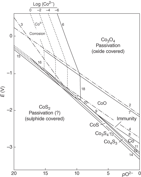
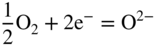
13.4 Corrosion Rate Measurements


13.5 Test Methods
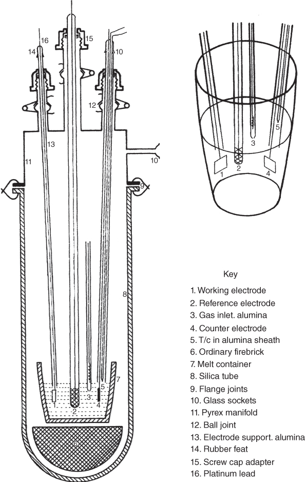
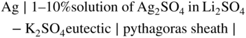
Type of material
Weight change (mg cm−2) and observed corrosion
Sample 1
Repeat sample 1
Sample 2
Repeat sample 2
Sample 3
Repeat sample 3
Pythagoras (sillimanite) (Anderman Ltd.)
−1.86 surface roughened
Severely cracked
−2.24 surface roughened
Severely cracked
−1.04 slightly rough
Few small fragments
Alsint (sintered alumina 99.7%) (Anderman)
−0.48
−0.64 two large fragments
−0.18
−0.28
−0.22 three large fragments
Morgan purox alumina
−0.24
−0.24
−0.20
−0.24
Pythagoras 1800 (Anderman Ltd.)
−0.12
Severely cracked
−0.38
Severely cracked
Severely cracked
Degussit AL 23 alumina
−0.46
−0.40
−0.20
−0.36
−0.24
Silica (thermal syndicate)
−2.66 extremely rough
−3.06 severely dissolved
−3.14 extremely rough
Mullite (Morgan Ref. Ltd.)
Large fragments
−0.30
−0.24
Large fragments
Large fragments
Time (h)
Weight (g)
Sample 1
Sample 2
0
1.0658
0.8086
24
1.0637
0.8031
48
1.0634
0.8020
72
1.0632
0.8014
96
1.0631
0.8010
 = 0.012 atm at 900 °C). Reference electrodes are best stored at a red heat; long cooling times to ambient are necessary to prevent cracking. Against an Au wire electrode at 900 °C, an “ideal” reference electrode has a potential of −160 mV. Its reproducibility, stability, reversibility, and unpolarizability was tested by Sequeira (1979) and found satisfactory for corrosion studies.
13.6 Fluorides
Alloy
Depth of attack, μm (mils)
Generala
Grain boundaryb
Mild steel
—
155 (6.1)
304
—
185 (7.3)
310
—
130 (5.1)
316
—
165 (6.5)
RA330
—
270 (10.6)
B
30 (1.2)
—
N
15 (0.6)
15 (0.6)
S
90 (3.5)
—
X
—
140 (5.5)
600
90 (3.5)
30 (1.2)
718
45 (1.8)
120 (4.7)
75
30 (1.2)
135 (5.3)
25
—
95 (3.7)
188
—
105 (4.1)
13.7 Chlorides
Alloy
Weight change (mg cm−2)
144h
456h
304
Disintegrated
—
316
Disintegrated
—
800
Disintegrated
—
800H
−310
Disintegrated
556
−250
Disintegrated
Nickel
Disintegrated
—
600
−280
Disintegrated
214
−120
Disintegrated
X
Disintegrated
—
N
Disintegrated
—
S
−400
Disintegrated
230
−300
Disintegrated
X‐750
Disintegrated
—
R‐41
−150
Disintegrated
188
Disintegrated
—
Alloy
Cr
Mo
Ni
Mn
Si
C
Fe
Co
Al
B
Cu
S
Zr
Y
W
La
N
Ta
Cb
Haynes 242
7–9
24–26
65
0.8
0.8
0.03
2
2.5
0.5
0.006
0.5
—
—
—
—
—
—
—
—
Alloy was designed for resistance to halides in general due to the low Cr content and elevated Mo content. It is close in composition to Hastelloy N, but it is
available, while Hastelloy N is currently not available
Inconel600
15.5
—
72
1
0.5
0.15
8
—
—
—
0.5
0.015
—
—
—
—
—
—
—
Low Cr content may aid in corrosion performance. Outperformed In 625 (20–25% Cr) in high temperature tests (Indacochea 2001)
HR 224
20
—
48.7
—
—
—
27.5
—
3.8
—
—
—
—
—
—
—
—
—
—
High Al content may help to provide resistance by formation of stable aluminum oxide
HA 214
16
—
75
0.5
0.2
0.05
3
—
4.5
0.001
—
—
0.1
0.001
—
—
—
—
—
High Al content may help to provide resistance by formation of stable aluminum oxide. This alloy also has lower Cr an Fe content, which were found to
dissolve preferentially more readily than Ni (Abramov 2010)
Haynes 230
22
2
57
0.5
0.4
0.1
3
5
0.3
0.015
—
—
—
—
14
0.02
—
—
—
High alloying with refractory materials, in the presence of Ni–Cr alloys, were found to provide better resistance to corrosion (Oryshich and Kostyrko 1985)
HA 556
22
3
20
1
0.4
0.1
31
18
0.2
—
—
—
0.02
—
2.5
0.02
0.2
0.6
—
3% Mo + 2.5% W + 18% Co may indicate better performance (Oryshich and Kostyrko 1985) despite the high concentration of Fe
HR 120
25
2.5
37
0.7
0.6
0.05
33
3
0.1
0.004
—
—
—
—
2.5
—
0.2
—
0.7
2.5% Mo + 2.5% W + 3% Co may indicate better performance (Oryshich and Kostyrko 1985) despite the high concentration of Fe
13.8 Nitrates/nitrites


13.9 Hydroxides
13.10 Carbonates
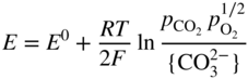
 and E0 is calculated to be near zero. T is temperature, F is Faraday’s constant, and R is the gas constant. There have been numerous electrochemical studies performed to gain a thermodynamic understanding of the system (Keijzer 2003; Keijzer et al. 1999; Nishikata et al. 1991; Vossen et al. 1994, 1996). Many other molten carbonate systems are being investigated for solar applications, but the MCFC conditions are not typical of TES conditions for several reasons.
Alloy
Cr
Mo
Ni
Mn
Si
C
N
Fe
Co
W
Al
Ta
La
Zr
Cu
S
P
Ti
Cb
B
Y
Ce
HA 556
22
3
20
1
0.4
0.1
0.2
31
18
2.5
0.2
0.6
0.02
0.02
—
—
—
—
—
—
—
—
Additions of minor alloying elements such as Al, La, and Zr, coupled with large additions of Ni, provide stable oxidation layers (Ozeryanaya et al. 1984)
In 600
15.5
—
72
1
0.5
0.15
—
8
—
—
—
—
—
—
0.5
0.015
—
—
—
—
—
—
High Ni content coupled with moderate Cr content
HR 224
20
—
48.7
—
—
—
—
27.5
—
—
3.8
—
—
—
—
—
—
—
—
—
—
—
High aluminum content (Oryshich and Kostyrko 1985)
In 625
20–23
8–10
58
0.5
0.5
0.1
—
5
1
—
0.4
—
—
—
—
0.015
0.015
0.4
3.15– 4.15
—
—
—
High Ni content coupled with moderate Cr and Mo content, and minor alloying elements, may provide good resistance to corrosion
Haynes 230
22
2
57
0.5
0.4
0.1
—
3
5
14
0.3
—
0.02
—
—
—
—
—
—
0.015
—
—
Minor alloying element La coupled with large additions of Ni, may provide stable oxidation layers (Ozeryanaya et al. 1984). Shown to have superior cycle
fatigue performance is also favorable for solar applications
HA 214
16
—
75
0.5
0.2
0.05
—
3
—
—
4.5
—
—
0.1
—
—
—
—
—
0.001
0.01
—
High nickel content, with high aluminum and small amounts of Zr (Oryshich and Kostyrko 1985) and Y (Wee and Lee 2006)
253 MA
20–22
—
10–12
0.8
1.4–2
0.05
0.14–0.2
63–68
—
—
—
—
—
—
—
—
0.04
—
—
—
—
0.03
High Si (Kruizenga 2012) and trace amounts of Ce (Wee and Lee 2006)
HR 120
25
2.5
37
0.7
0.6
0.05
0.2
33
3
2.5
0.1
—
—
—
—
—
—
—
0.7
0.004
—
—
2.5% Mo + 2.5% W + 3% Co may indicate better performance (Oryshich and Kostyrko 1985) despite the high concentration of Fe
13.11 Vanadates


13.12 Sulfates
13.12.1 General Aspects

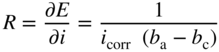
13.12.2 Metal–Metal Ion Systems
System
Li2SO4–K2SO4, 625 °C (mV)
Li2SO4–K2SO4–Na2SO4, 550 °C (mV)
Li2SO4–K2SO4–Na2SO4, 625 °C (mV)
Pd2+–Pd
+541
+518
+530
Rh3+–Rh
+387
+370
Cu2+–Cu+
+51
+55
Ag+–Ag
0
0
0
Cu+–Cu
−202
−220
−206
Co2+–Co
−689
−714
Fe2+–Fe
−930
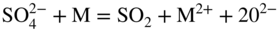
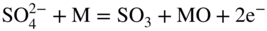
13.12.3 The Oxygen Electrode
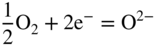
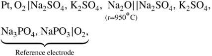
 = CO2 + O2− controls the oxide ion concentration in this case. Flood and Forland investigated the overpotential associated with the anodic evolution of oxygen in fluoride melts containing sulfate, carbonate, orthophosphate, and silicate using an O2∣Pt electrode. At high temperature (900 °C) and low current densities, a Tafel slope of RT/3F was found; at high c.d. at 700 °C, steady‐state measurements gave a Tafel slope of RT/F. The activation overpotential was found to decrease in parallel with the XO bond strength in the order
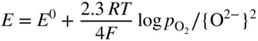
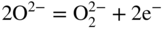
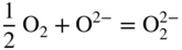
13.12.4 Electronation of Sulfate Species
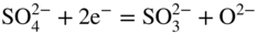
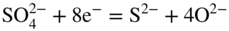
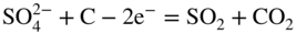
 anions. Attempts to demonstrate sulfate reducibility via its acid (SO3) component proved difficult because the dissociation of sulfate ions into sulfur trioxide and oxide is negligible and a further complication results from the dissociative equilibrium
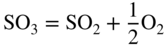
13.12.5 De‐electronation of Sulfate Species
 anion represented by the charge transfer equation:
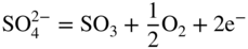
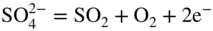
 oxidation to SO2 and O2 at the cathode and anode, respectively. Addition of NaCl into the sulfate did not reduce its stability range.
13.12.6 Corrosion Potential Measurements
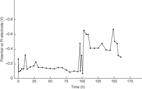
13.12.7 Polarization Studies
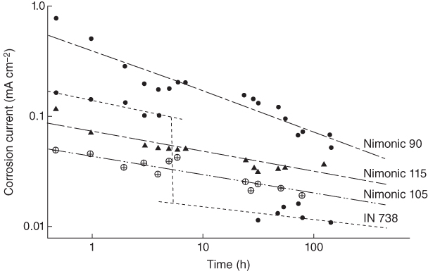
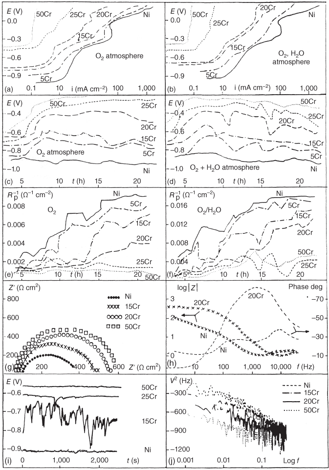

 . The passive state of the studied specimens, accompanied by the enhancement of their film stability, predominates when the alloys contain more than 20% Cr. Microscope, electron probe, and X‐ray studies, not reported here, showed that the principal corrosion products are NiO, Cr2O3, Ni3S2, and CrS (Sequeira 1998).
13.12.8 Other Measurements
 in chloride molten salts. The investigation of the reducibility of sulfate ions was made by several workers by studying solutions of sodium sulfate in the LiCl–KCl eutectic. A chronopotentiometric study of the dissociation of sulfate ions in molten equimolar NaCl–KCl at 750 °C was also carried out. Moreover, K/Na/Mg and Zn/K chlorides containing sulfate have also been used as reaction media for electrochemical studies.
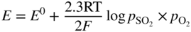
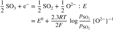
13.13 Prevention of Molten Salt Corrosion
13.14 Summary
References
Further Reading
Corrosion in Molten Salts
13.1
13.2
13.3
13.4
13.5
13.6
13.7
13.8
13.9
13.413.4
13.10
13.11
13.12
13.13
13.14
13.15
13.16
13.17
13.18
13.19
13.20
13.21
13.22
13.23
13.24
13.25
13.26
13.4
13.27
13.18
13.17
13.28
13.29
13.30
13.31
13.32
13.313.3
13.33
13.34
13.35
13.36