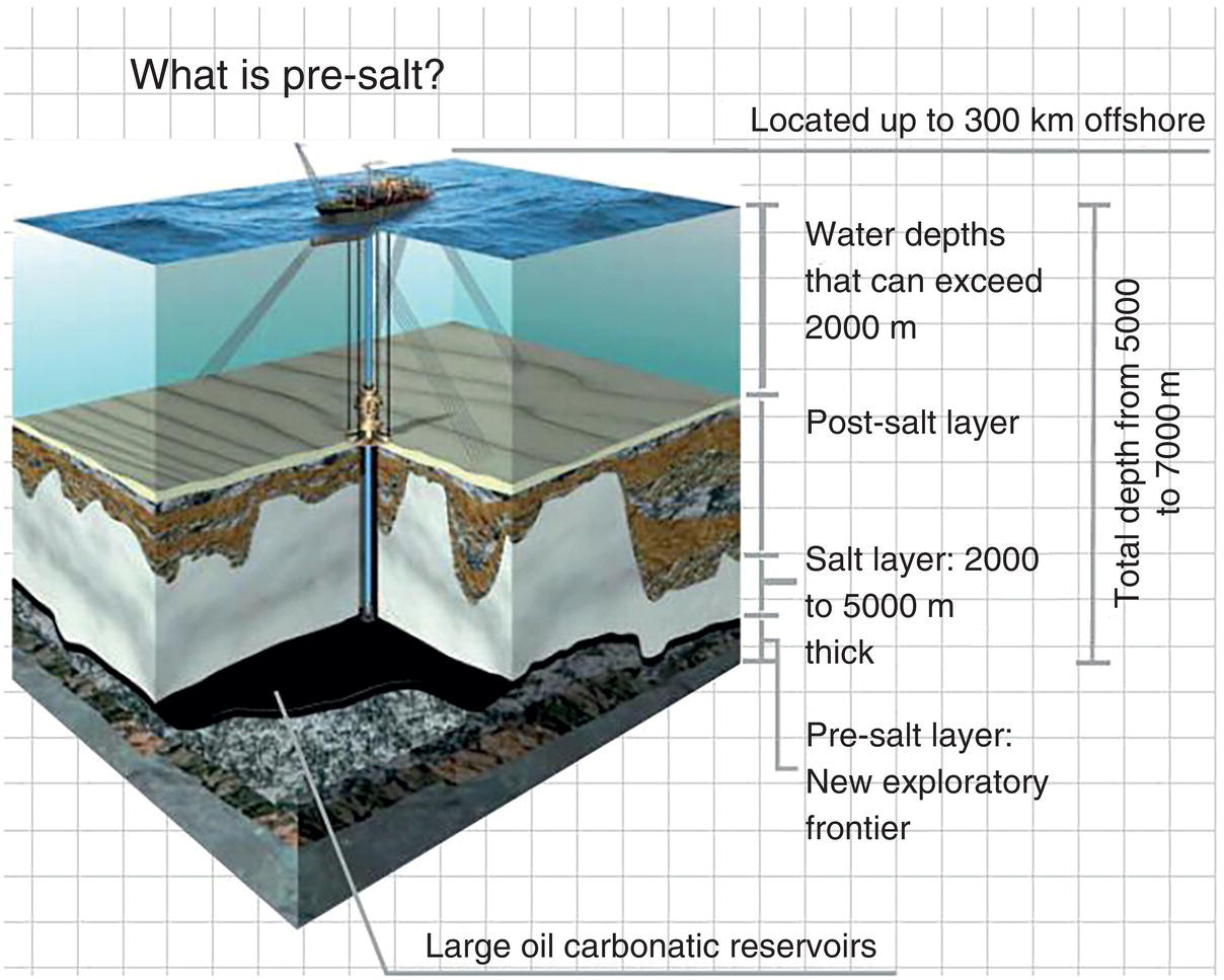
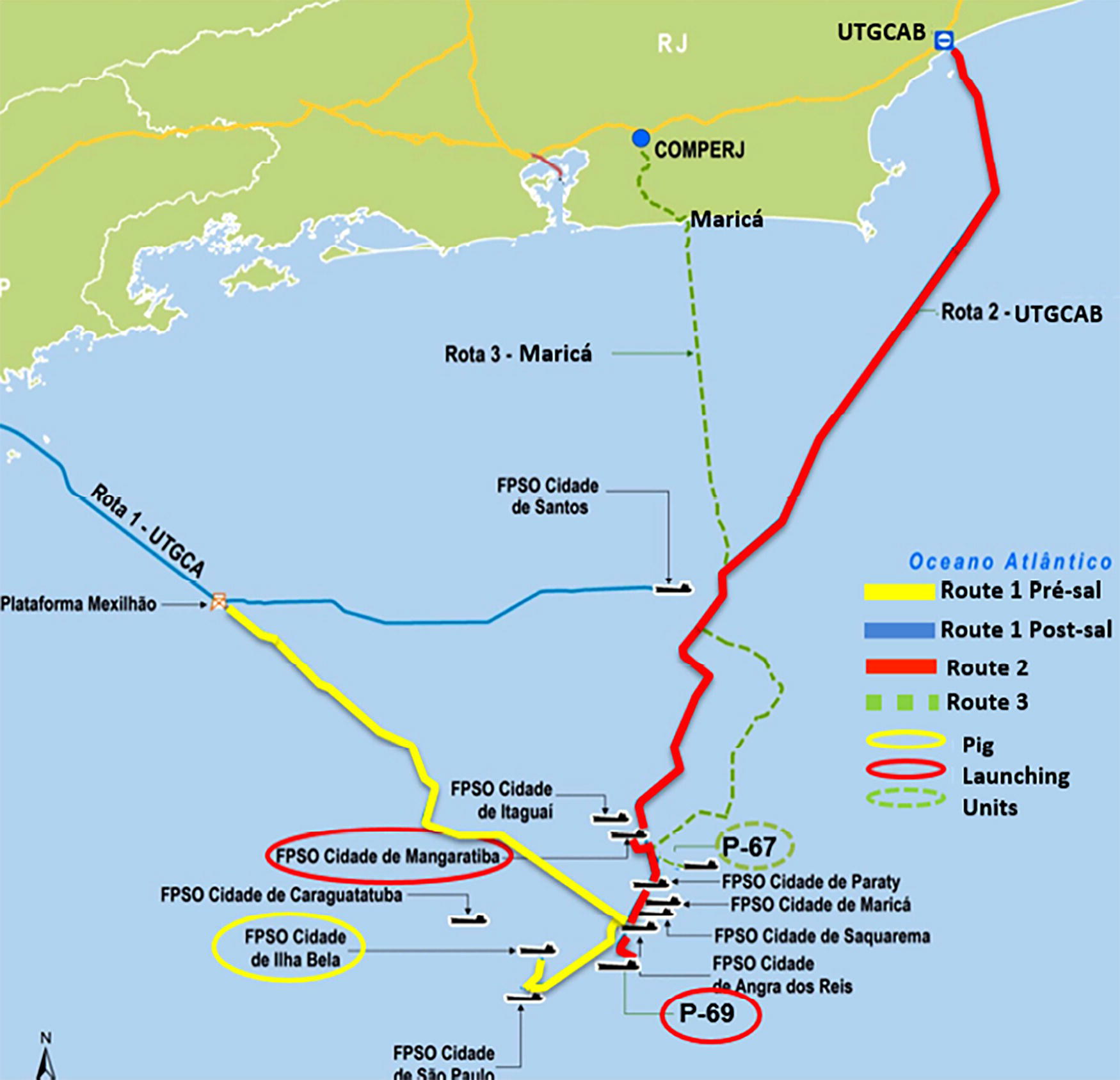
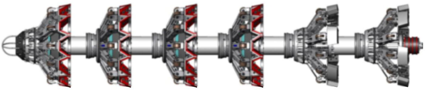
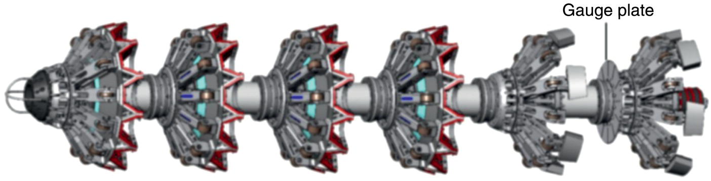
Luciano Baptista1, Tom Steinvoorte2, Stephan Harmsen2 and Carlos Enrique Sabido3 1Rosenbra Engenharia Brasil LTDA, Rio de Janeiro, Brazil 2Rosen Europe B.V., Oldenzaal, The Netherlands 3Rosen Technology & Research Center, Lingen, Germany In-line corrosion inspections with magnetic flux leakage (MFL) or ultrasonic technology (UT) have become standard in pipeline integrity assessments worldwide. Lately, ultrahigh-resolution geometry inspection based on eddy current methods (EC) has been established to assess more accurately the internal pipeline geometry and internal corrosion; it deploys less restrictive tools that can operate independently of the pipeline medium. Approximately 60% of the world’s gas, oil, and product pipelines can be inspected with off-the-shelf inspection tools. In the past, the remaining 40% of pipelines were often classified as “unpiggable.” A large proportion of these unpiggable pipelines are offshore and multidiameter; often, they feature difficult flow conditions and very challenging Outer Diameter (OD) ratios. Today, it is possible to develop individualized inspection solutions for multidiameter pipeline systems. The development of such solutions can already be incorporated into the Front End Engineering Design (FEED) process for these offshore structures. On the other hand, a great number of pipelines were constructed and laid in times when in-line inspection (ILI) was not available or required. Quite often, the passage of these offshore pipelines is restricted. This chapter presents the development of a 16 in./22 in. ILI tool and a successful application survey in a 452-km-long deepwater passage through flexibles, complex installations, and combinations thereof (Y-pieces, bends, jumpers, T-pieces, valves) in a high-pressure, heavy-wall, high-flow offshore pipeline. In a team effort involving the pipeline operator and the inspection company, a solution was developed for a challenging pipeline that would have been considered unpiggable in the recent past. First explored in 2006, the Brazilian presalt oil region is an offshore reserve rich in oil and gas trapped below a 2000-m-thick layer of salt, which itself is located below a 2000-m-thick layer of postsalt sediments, as illustrated in Figure 73.1. The presalt denomination is used to designate geologic layers that were formed before the salt layer accumulated above it (Figure 73.1). The Brazilian presalt cluster structure was created around 160 million years ago from the separation of the continental superstructure Gondwana into the American and African continents. The rifting created the conditions necessary for the deposition of sediments and, as sea water filled the space between them, a low-energy and high-salinity environment propitious to the development of bacterial colonies was formed. The secretion of these bacteria, allied with the precipitation of carbonate salts, created nuclei for the formation of microbialites (carbonate rocks) on which oil accumulated. Most of the oil found has a presalt origin. In some cases, the salt shifts and gives way to the oil, which then accumulates in the postsalt rocks. Even though they have the same origin, the two oils have differences. In the postsalt case, bacteria may consume the lighter part of the oil, from which gasoline and diesel are extracted. For the presalt oil, a high reservoir of rocks such as coquinas and volcaniclastics allied with a higher temperature—above 80 °C, given the greater depths—creates a condition that sterilizes the oil and preserves its qualities. Figure 73.1 Presalt underwater layers. The presalt discoveries are among the most important discoveries made in the world over the last decade. This province comprises large accumulations of excellent-quality light oil with a high commercial value—a reality that puts Brazil in a strategic position to meet the great global demand for energy. The development of presalt fields faces many challenges, including harsh oceanographic conditions. The Brazilian Santos and Campos basins, for example, play host to an ultradeepwater environment with no preinstalled production infrastructure. The basins are located 300 km off the coast (Figure 73.2), with water depths reaching deeper than 2 km and an oil reservoir nestled 5 km below the seabed under a 2-km-thick salt layer. To discover these reserves and operate efficiently in the deep water, operators needed to develop new technologies and work in collaboration with suppliers, universities, and research centers. During the subsea engineering of the pipelines, it became clear that the pipeline design would not be standard—particularly for the export lines transporting the associated gas from offshore production to onshore facilities. Figure 73.2 shows the pipelines system to be inspected by the proposed solution, with focus on the launching areas and the schematics of distances to be achieved for each ILI campaign. Input regarding the possibilities and limitations of ILI technology provided the operator’s engineers with the ultimate flexibility in designing a multidiameter pipeline system while ensuring that the integrity of these extremely valuable assets could be managed using ILI tools. Since the initial discussions, the first part of the pipeline system has been completed; now in operation, it is due for its first in-service inspection. The operator’s pipeline engineers finally settled on a pipeline system with the following main parameters: Although an MFL-based solution can accommodate the internal diameter range, the thick-walled pipe requires that the MFL technology travel at a maximum speed of 1 m/s in the larger diameter. The flow in the pipeline, however, vastly exceeds the capabilities of a multidiameter MFL tool. Figure 73.2 Pipeline system. A remedy for these speed excursions would be a speed control unit (SCU) added to the solution. However, due to the multidiameter design of the tool, the area in which the SCU can be positioned is limited to a range that is not large enough to create the needed bypass for slowing the tool to the necessary speed. As it was also not feasible for the operator to interrupt operations by reducing the gas velocity, another solution had to be found. The engineers agreed to settle on IEC technology instead, due to the following factors: A new multidiameter cleaning tool has been developed with nylon brushes and magnet rings. The newly designed cleaning tool with so-called umbrella cups is shown in Figure 73.3. The umbrella design allows the cleaning tool to pass over a wider ID range than single-diameter pull units, thus enabling it to clean and inspect pipelines with multiple diameters (Figure 73.3). The ID operation range of this tool is from 340 to 610 mm for a safe passage and sealing at any time. During the cleaning of the actual pipeline system, three main aspects have to be considered when engineering the tool setup: sealing length, cleaning effectiveness, and smooth run behavior. The cleaning tool design consists of six segments guided by four umbrella cups and two spring-loaded brush segments. The first four umbrella cups ensure the sealing. This tool design ensures a large sealing length, sufficient for the passage of different installations like T- and Y-pieces. Following these units are two spring-loaded brush units. The six segments are connected with spring-stiffened cardan joints. The basic material used for the tool bodies is stainless steel. Bolting is 8.8-grade galvanized. All bolts are secured with self-locking nuts. The front module is equipped with a conical-shaped polyethylene buffer and two steel ropes that make it possible to pull the tool during loading and retrieving. The elastic elements of the umbrella cups are made of RoPlasthan polyurethane material. As for the ILI tool, two different shore hardnesses are used: 95-shore hardness for the front and 75-shore hardness for the rear polyurethane wedges, which hold the sealing membrane. The harder shore harness is for the stability of the cup, while the softer shore harness is for better sealing. The tool is equipped with two ferrite magnet rings to collect loose metal components, such as rust, welding rods, mill scale, and other ferrous deposits. The spring-supported nylon brushes are forced against the pipe to effectively remove debris from the inner pipe wall. The brushes are mounted on spring-loaded arms to apply consistent pressure against the pipeline wall. To protect the flow coating of the pipelines, all brushes are made of nylon (polypropylene) brush material. To verify the internal diameter of the specific pipeline, the tool can be equipped with a gauge plate between the first and second brush segment, as shown in Figure 73.4. The gauge plate has a thickness of 5 mm and has 12° × 30° radial incisions. The gauge plate is made of aluminum. The gauge plate gives a first impression of whether larger obstructions are to be expected in the pipeline and whether the following tools can safely pass the pipeline. The type of gauge plate and the gauge plate position are the result of ROSEN’s long-term experience with gauging surveys. Figure 73.3 General sketch of the 16/24 in. cleaning tool. Figure 73.4 General sketch of the 16/24 in. cleaning tool with equipped gauge plate. Table 73.1 Specifications of the Multidiameter Cleaning Tool The specifications of the multidiameter pull unit with brush tender and gauge plate are shown in Table 73.1. The ILI tool consists of the multidiameter pull unit and the measurement unit (Figure 73.5). The pull unit is a multidiameter construction. The multidiameter umbrella cups are designed to have optimal sealing in all diameters. ROSEN designed the pull unit with four sealing planes. This ensures optimal sealing not only in straight pipes but also in various installations such as T- and Y-pieces, bends, valves, etc. The four sealing planes ensure that at least one plane always seals and pulls the tool forward, even if other sealing planes do have bypass caused by, e.g., a T-offtake or Y-piece. All four sealing units were also designed to carry battery packs as the tool’s electrical supply. The battery capacity was calculated to include a safety margin. Semistiff joints ensure a stable position in the pipeline. The joints are stiffened with springs. The elastic elements of the umbrella cups are made of RoPlasthan 1200 polyurethane material. For further information, please see the RoPlasthan 1200 data sheet [4]. Two different shore hardnesses are used: 95-shore hardness for the front and 75-shore hardness for the rear polyurethane wedges, which hold the sealing membrane. The harder shore harness is for the stability of the cup, while the softer shore harness is for better sealing. The measurement unit was designed to measure internal corrosion and pipeline geometry in a multidiameter pipeline. There are four measurement modules with multiple sensor arms each to achieve appropriate pipe wall coverage in the maximum ID. The sensor arms are spring-loaded, which ensures that all arms always follow the pipeline wall. Each sensor arm consists of two sensors: one for the diameter change measurement (measures the angle of the sensor arm), and one for the measurement of the internal corrosion and the distance to the pipe wall. Outer support wheels on each sensor arm decrease friction and avoid scratches in the internal flow coating. Instead of the sensors touching and rubbing the pipeline wall, the wheels roll along the pipeline wall. The outer support wheel sealing planes have polyurethane umbrella cups. The specifications of the ILI tool are listed in Table 73.2. Figure 73.5 IEC tool assembly. Table 73.2 IEC Tool Specifications Testing can lead to failure, and failure leads to understanding. After the detailed design, production, and assembly of all tools, they underwent the most stringent tests to prove they were up for the challenges ahead. Four different setups were tested in three different diameters at both high and low differential pressures. In total, 24 bypass tests were performed. The objective of the bypass test was to record absolute bypass (flow) over one umbrella seal in the forward direction to confirm the ability to launch with low flow and maintain a constant velocity given the low flow. Due to the low-flow sections in the pipeline system, it was decided to test different polyurethane hardnesses. A combination of two different cup variants was used for the bypass tests, and the pump test results to decide which cup variant is preferable. Bypass was measured under low and high differential pressures, and no visual damage occurred. Data for pressure and flow are shown in Figure 73.6. Figure 73.6 shows pressure and flow × time graph, confirming that the pulling unit of the ILI tool is able to provide enough sealing for launching and keep the tool running safely and over passing all installations in the pipelines system. A multidiameter test loop represented the most challenging combination of installations of the complete pipelines system (Figures 73.7 and 73.8). The tool was pumped through the test loop using water. For such project and tool development, pump tests are performed to: Figure 73.6 Example of bypass test graphs of pressure and flow. Figure 73.7 Test loop sketch. Figure 73.8 Test loop ready for use. The ILI tool was switched on during the pump tests so that the functionality could be checked. The pump test loop did not have any artificial anomalies. The test loop consisted of 51 items, the most challenging combinations of installations to prove passage, proper run behavior, and acceptable differential-pressure requirements. An original offshore Y-piece combination was installed, weighing almost 10 tons. In total, six pump tests were performed. Figure 73.9 shows pressure peaks while the ILI tool has passed the most critical installations of the test loop. Figures 73.6 and 73.9 are screenshots from pressure test reports showing the type of information that can be generated. Test lines contained artificial internal metal loss and dent anomalies to prove IEC performance. Pull tests were carried out in five different diameters. In each diameter, the tool was pulled at three different velocities. Each test was repeated twice at the same velocity, and a total of 30 pull tests were performed. Pull tests were performed to: Figure 73.10 illustrates the IEC detection and sizing capabilities (in metric and imperial units). For an aspect ratio of D/d ≥ 3, where D and d denote defect diameter and depth, respectively, and above a minimum diameter of 10 mm (0.4 in.) and depth detection threshold of 1.5 mm (0.06 in.) at POD 90%, full detection and sizing capabilities are provided (green-shaded, lower right, area). For defect diameters above 30 mm (1.2 in.), a maximum defect depth of 10 mm (0.4 in.) can be sized. For defects that do not follow the aspect ratio or exceed a depth of 10 mm (0.4 in.), detection is still possible (blue-shaded, upper left, area). All tests were successfully completed in accordance with the project schedule. Minor improvements were made to the tools based on intermediate test results. Major changes were not required, and the scheduled contingency period was not needed. This shows that the multidimensional systems experience and excellent teamwork delivers good tool designs! Figure 73.9 Example of flow and pressure chart during pump tests. Figure 73.10 IEC technology detection and sizing capabilities. ([1]/with permission of ROSEN Group.) Over 450 pages of customized documentation were issued to the client. Quality in a service is not what you put into it; it is what the customer gets out of it. The client was kept informed throughout the preparation phase. Ideas and concepts were shared with the client early on. Early-phase documents included the following: These documents were followed up by official QAQC-checked documents, including design reports and test result reports. This open, transparent, and proactive way of communicating ensured a high level of trust between both parties. Furthermore, by being proactive, early feedback from the client made it possible to address any issues and changes in scope at an early stage, before they could have an impact on the project schedule. After the design and test phases, the onsite execution phase began. Recently, ROSEN reached the milestone of performing the first successful IEC run in the project. The inspection of the Route 2.1 pipeline, which runs from FPSO Cidade de Mangaratiba to the UTGCAB Cabiunas terminal, had the following challenges: In addition to the technical challenges, political and economic factors also played a role in the project. Hydroelectricity is the main source of energy in Brazil. During the ILI run, the country was facing the worst water crisis of the past 91 years, which meant that the government was pushed to find other sources of energy to compensate for this scarcity of water. The alternative is to use thermoelectric systems to generate energy, which requires large quantities of natural gas. Santos Basin is the largest provider of natural gas in the country, and the pipelines are of extreme importance in maintaining the country’s gas supply. Gas flow in the lines can reach up to 8 m/s during normal operation. Because this flow was too high to perform the inspection, the flow was reduced as much as possible during the pigging activities. During that energy crisis moment, reducing the flow was not desired by anyone besides us. The Brazilian minister of energy contacted the operator to request an increase in the flow of gas to feed more volume to the thermoelectric plants. That would have meant that the pigging activities would have to be put on hold until the start of the rainy season, when the hydroelectric units can return to normal operation. After discussion between the government and operator, pigging activities began for the first pipeline, Route 2.1. The multidiameter cleaning and ILI tools were equipped with an ITX 804 HP transmitter and a radioactive isotope supplied by a third-party provider. The ITX transmitter is designed to withstand pressures up to 300 bar (30 MPa). The ILI run was completed within the estimated time, and the recorded geometry, metal loss, and XYZ data were of good quality, providing 100% coverage. After traveling 384 km and passing complex installations, the IEC tool was received in very good condition. The early involvement of the engineering team contributed to significant cost savings for the client during the pipeline construction. By developing a tailored ILI solution, ROSEN supported the operator in managing the integrity of their pipelines, achieving compliance with local regulations, minimizing the operational impact on flows, and ensuring the line could safely transport gas to supply energy.
73
Deepwater, High-Pressure, and Multidiameter Pipelines—A Challenging In-Line Inspection Project
73.1 Introduction
73.2 Background
73.3 Challenge
Maximum water depth:
2230 m
Maximum pressure:
335 bar (33.5 MPa)
Maximum wall thickness:
1.452 in.
Maximum ID range:
14.70–21.75 in./15.40–22.30 in.
Maximum length:
452 km
73.4 Solution
73.5 Scope
73.6 Tool Design
73.6.1 Multidiameter Cleaning Tools
Tool Parameter
Tool Value
Tool length
3202 mm
No. of segments
6
Min. ID passage in straight pipe (designed/tested)
340 mm/344 mm
Min. ID bend passage (2.5D in 18 in.) (designed/tested)
345 mm/356 mm
Max. operating pressure
300 bar (30.0 MPa)
Min. product temperature
0 °C
Max. product temperature
65 °C
Max. tool run velocity
5 m/s
Recommended tool run velocity
1–2 m/s
Operational weight
580 kg
Gauging plate outside diameter
372 mm/355 mm
73.6.1.1 Multidiameter Cleaning Tool Specifications
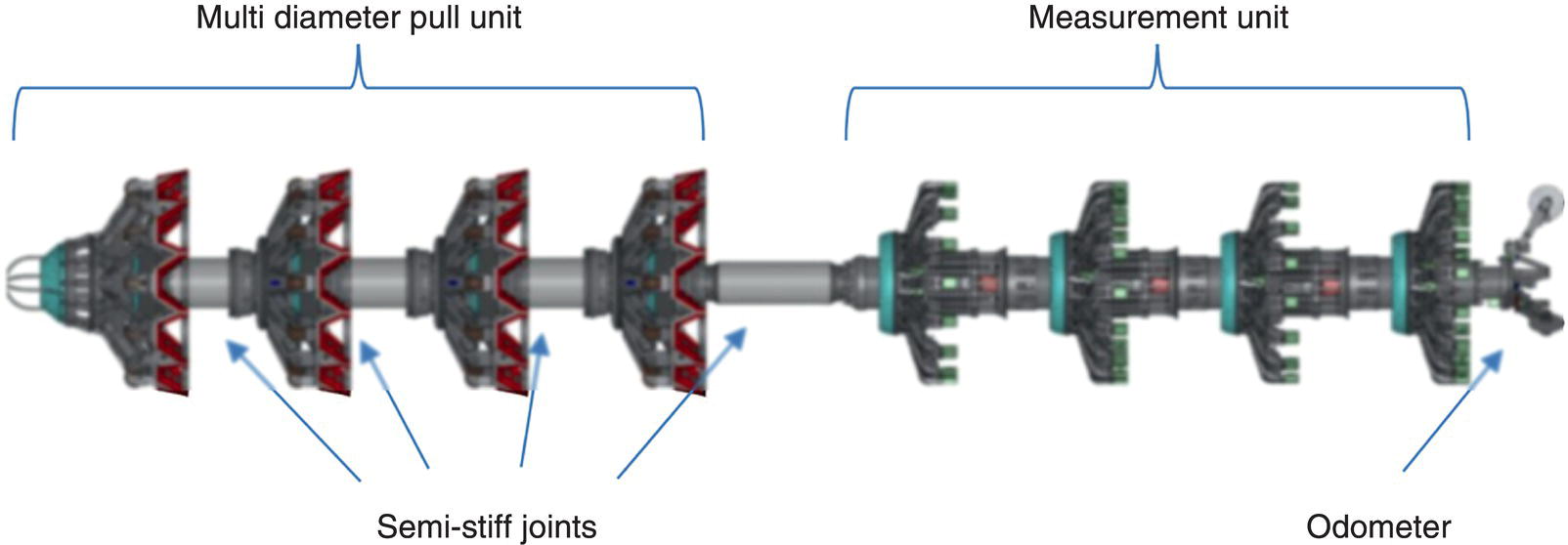
73.6.2 Key Design Features of the ILI Tool
73.6.2.1 Multidiameter Pull Unit
73.6.2.2 Measurement Unit
73.6.2.3 ILI Tool Specifications
Description
Value
Corresponding Pipeline Value
Tool length
4500 mm
4769 mm (min. launcher length)
Tool weight
760 kg
Min. bend radius
2.5D
2.66D
Min. ID in straight pipe
340 mm
370 mm
Min. ID in bend
350 mm
393 mm
Max. ID in straight pipe
570 mm
565 mm
Battery capacity
95 h (+10% safety margin)
82 h
73.7 Testing
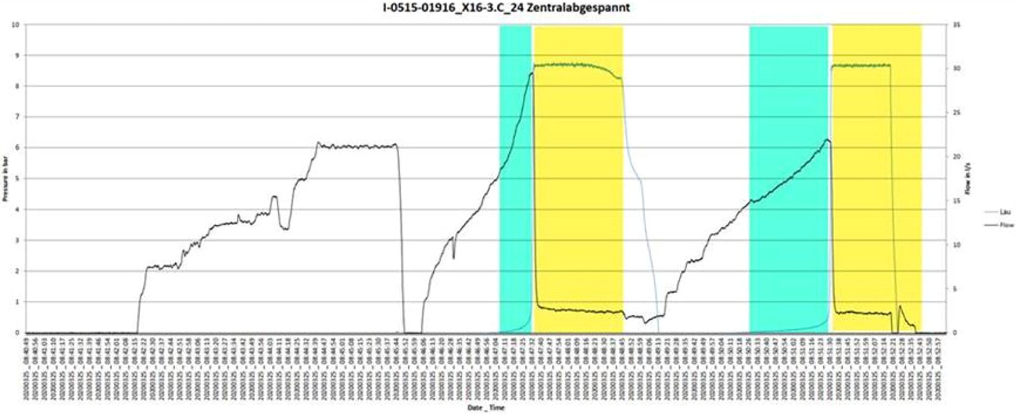
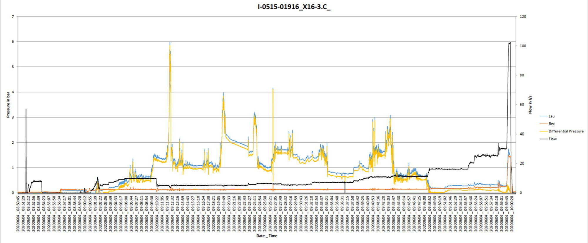
73.7.1 Bypass Tests
73.7.1.1 Bypass Test Objective
73.7.2 Pump Tests
73.7.2.1 Pump Test Objectives
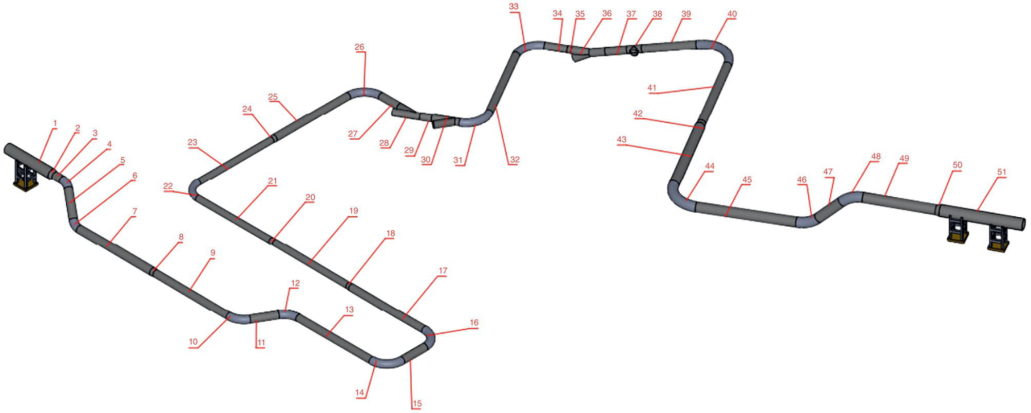
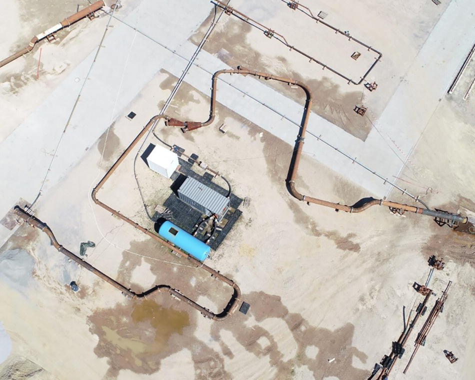
73.7.2.2 Test Loop Assembly Characteristics
73.7.3 Pull Tests
73.7.3.1 Pull Test Objectives
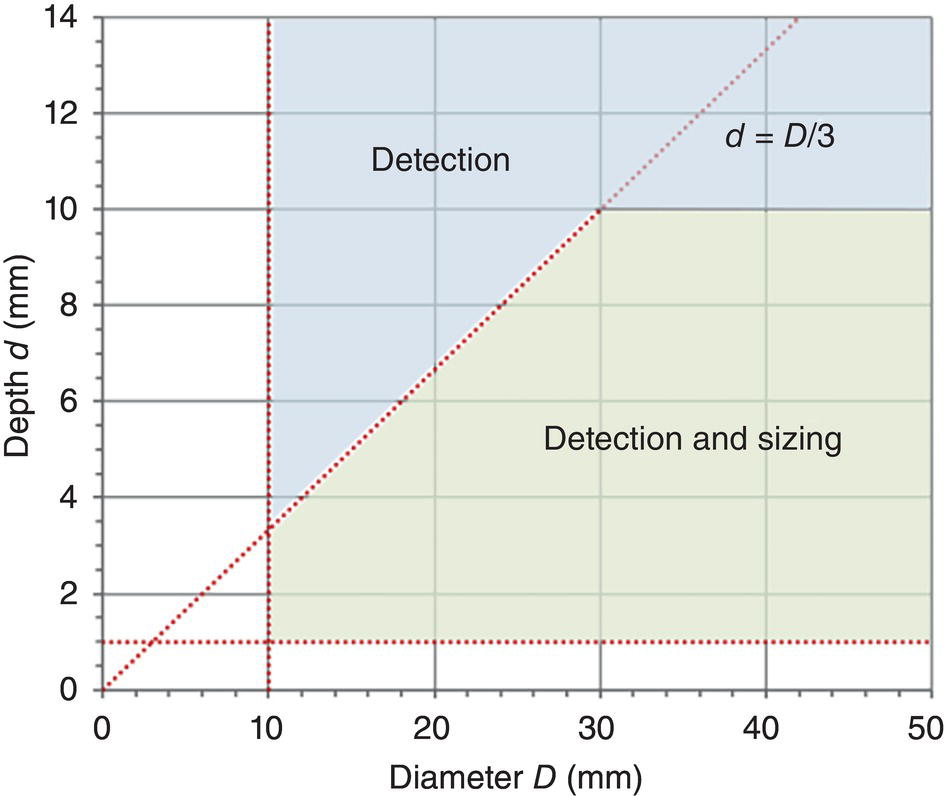
73.7.3.2 IEC Detection and Sizing Capabilities
73.8 Gauging and Inspection Runs
73.8.1 Key Challenges
73.8.2 Cleaning, Gauging, and Inspecting Route 2.1
73.9 Benefit
References