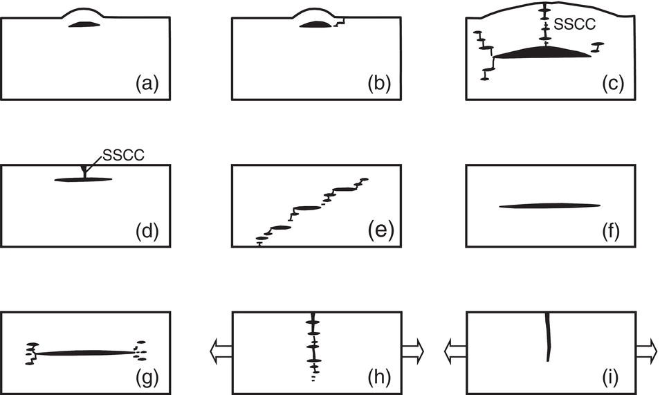
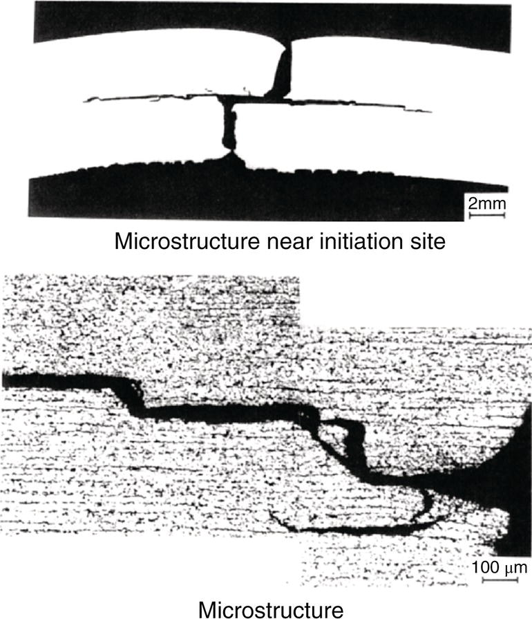
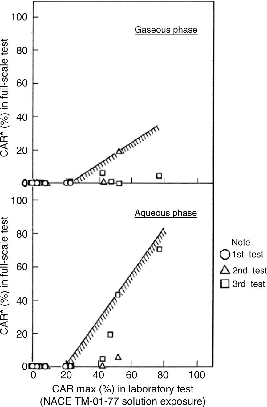
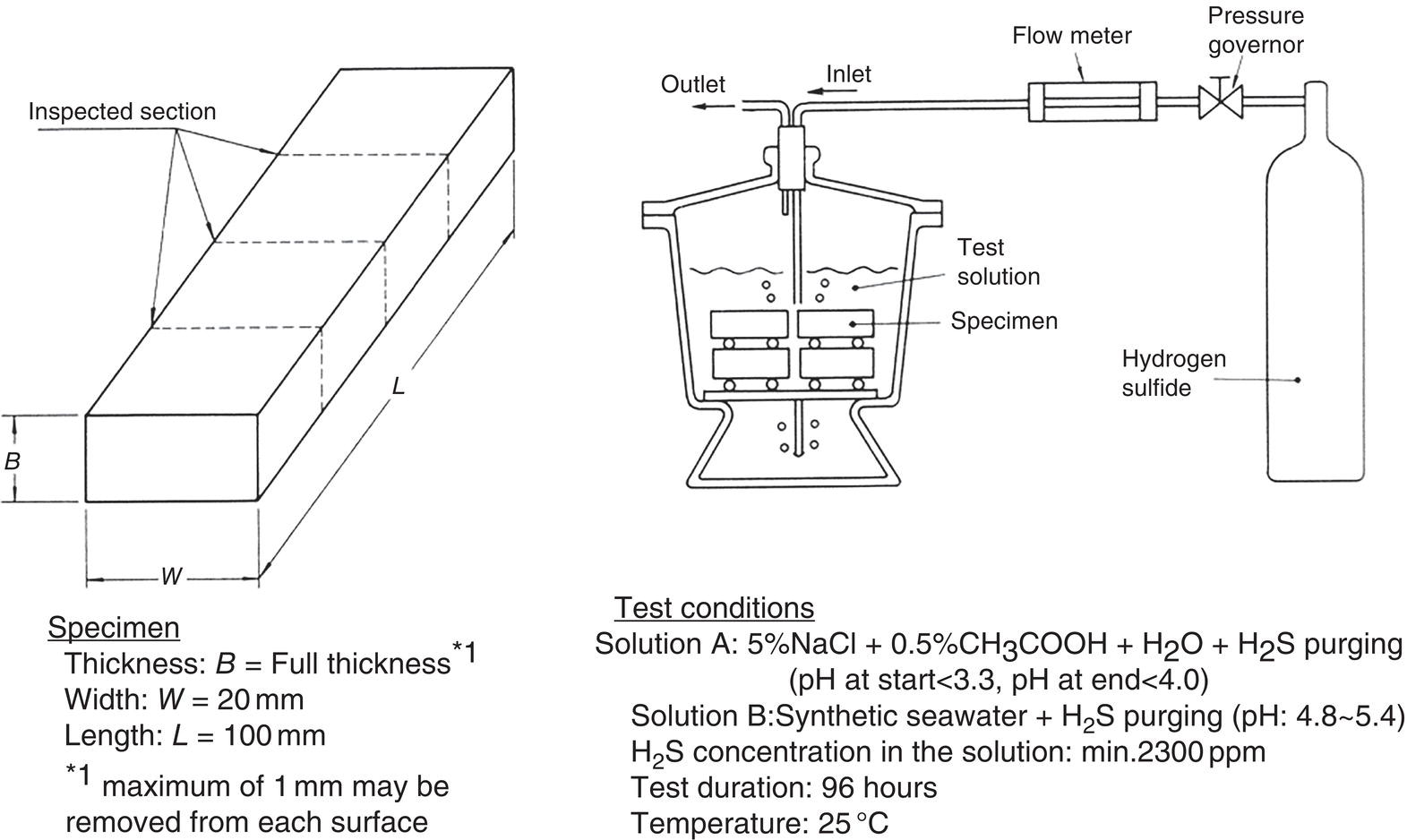
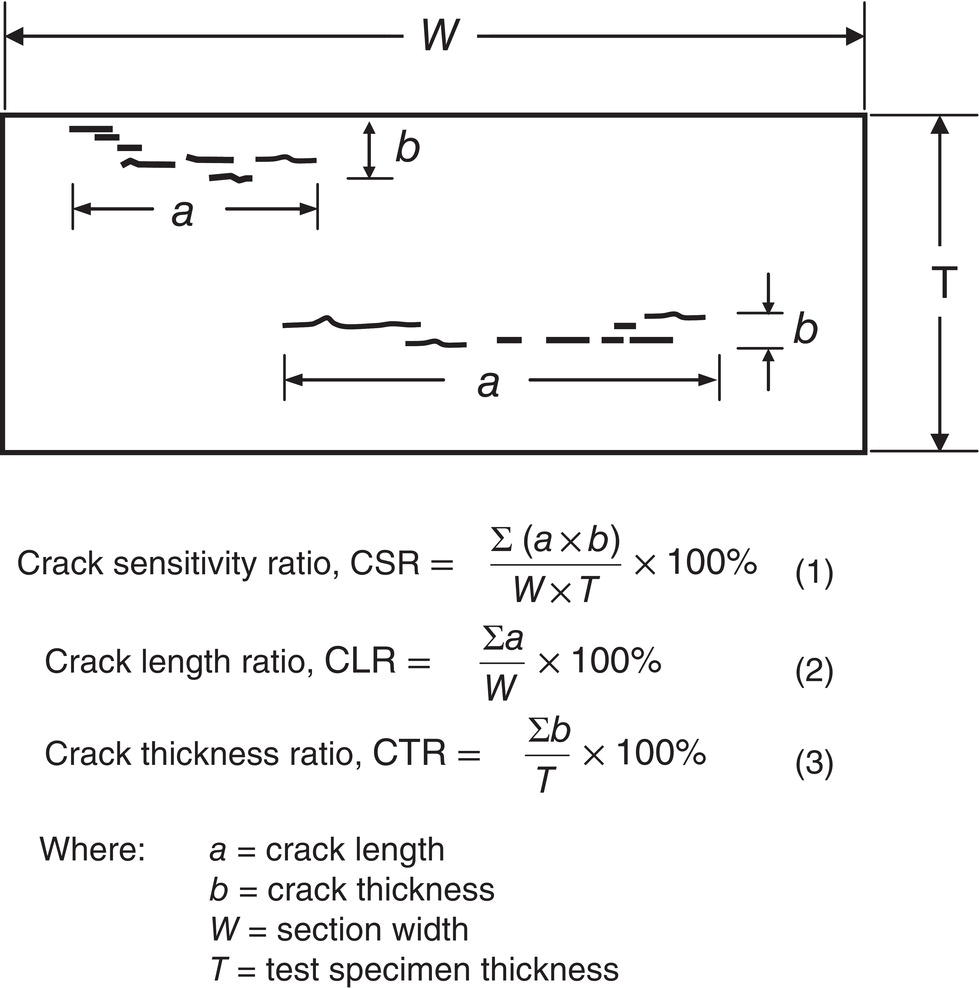
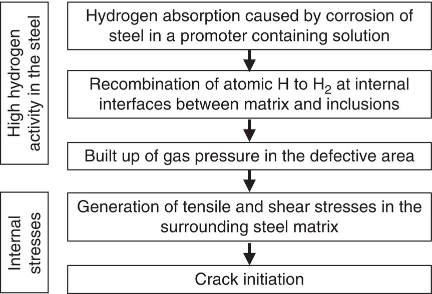
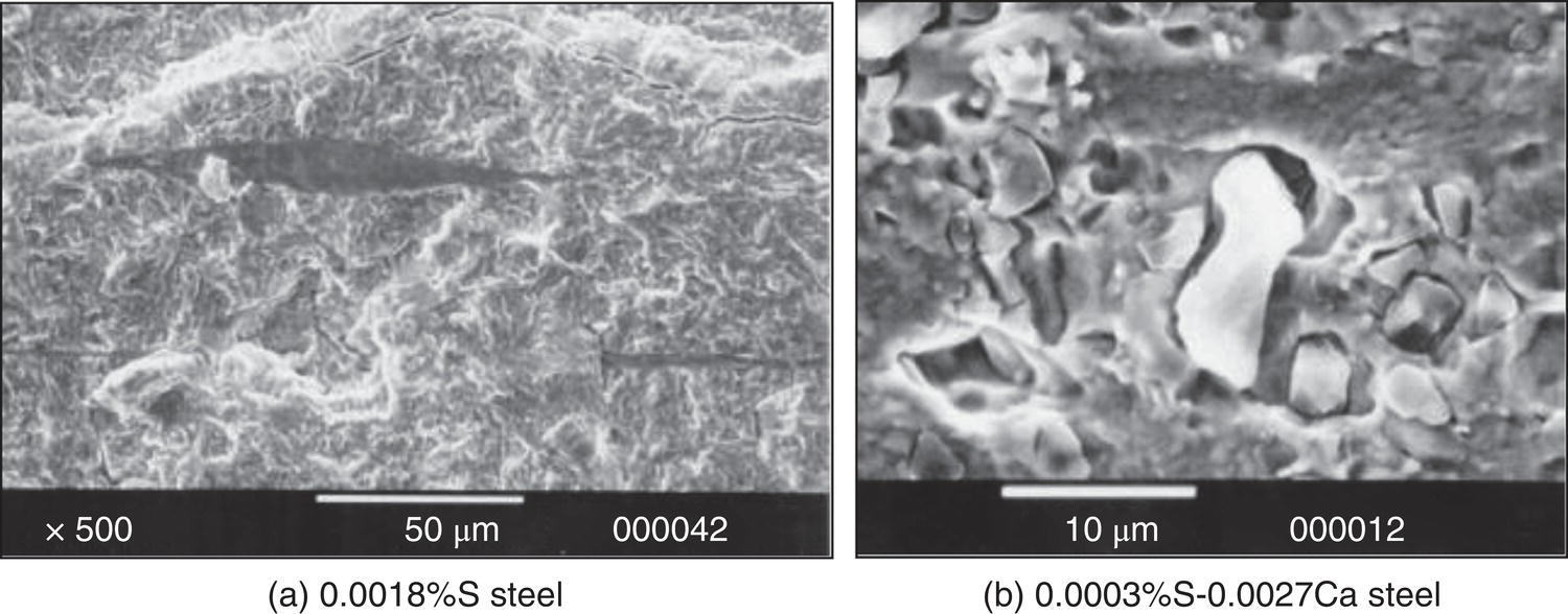
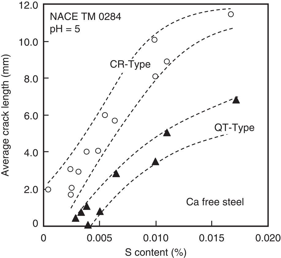
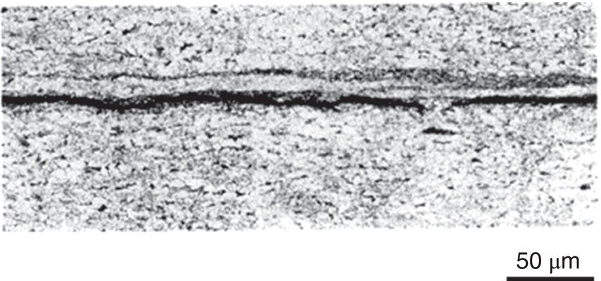
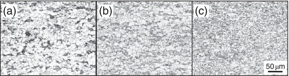
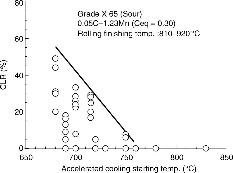
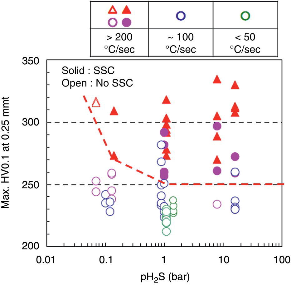
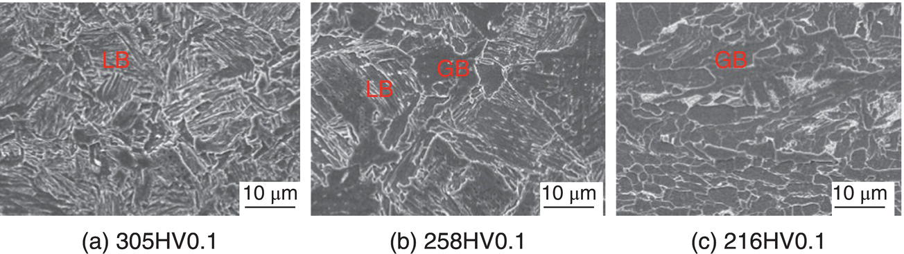
Nobuyuki Ishikawa JFE Steel Corporation, Tokyo, Japan Linepipe material for sour gas service primarily needs to have strong resistance to the cracking caused by hydrogen invasion from gas containing wet H2S. Morphologies of the cracking caused in carbon steel or low alloyed steel under wet H2S environment are illustrated in Figure 20.1 [1]. Hydrogen-induced cracking (HIC) occurs without any applied stress, and there are several types of cracking morphologies, as shown in Figure 20.1a–g. Several terminologies have been used to describe these types of cracking, such as blister cracking, hydrogen-induced blister cracking, hydrogen-induced stepwise cracking, stepwise cracking, and so on. On the other hand, sulfide stress cracking (SSC) or sulfide stress corrosion cracking (SSCC), Figure 20.1h and i, occurs under the presence of a tensile stress field. The SSC has been investigated since the 1960s [2–4], and SSC testing method and guidelines for preventing SSC have been established in NACE MR 0175/ISO 15156-2 [5]. On the other hand, after the accident involving failure of a sour gas pipeline in the 1970s [6, 7], extensive studies have been conducted to investigate the HIC mechanism and to improve material resistance [8–16]. Laboratory testing methods to evaluate the material resistance to HIC have been standardized in NACE TM 0284 [17] and EFC 16 [18]. In addition to the sour resistant properties, higher strength, toughness of base metal and weldments, and many other materials properties are required for the linepipe steels because of the demand for cost reduction in pipeline construction by applying higher grade linepipe and for expanding applications toward the harsh environmental fields such as deep water and cold climate. Recent SSC failures in pipelines operated under severe sour conditions, high concentration and high pressure of H2S, have required further efforts in material development for pipeline safety. Therefore, appropriate materials must be selected for pipelines that are to be used under various environmental conditions. Reducing nonmetallic inclusions and center segregation is the basic measure to prevent initiation and propagation of HIC in linepipes used in wet H2S environments. Microstructural control of the base metal is also important for achieving both higher HIC resistance and other mechanical properties. To select appropriate linepipe steels and develop sour-resistant steels used in severe environmental conditions, it is important to understand the behavior of HIC in the sour pipeline and the evaluation method for sour resistance properties, which are introduced in this chapter first. Then, material design concepts for controlling HIC resistance properties in the production of steels used in sour gas pipelines are summarized. Technical guidelines for SSC are discussed in Chapter 57 of this handbook, whereas recent developments in SSC-resistant materials are presented in this chapter. Failure events caused in actual gas transmission pipelines in the early 1970s [5, 6] initiated the extensive investigations for simulating HIC in laboratory specimens and full-scale tests [19–24]. One of the full-scale tests with pressurized wet gas containing H2S was conducted by the HLP Committee of the Iron and Steel Institute of Japan [20]. Several large-diameter pipes of strength grade up to X65 with different susceptibility to HIC were connected and installed in the test rig that can circulate pressurized gas with brine in the bottom of pipes. Natural gas containing H2S gas was used for the test. Total gas pressure was 8.4 MPa and partial H2S pressure was up to 1.5 MPa. Susceptibility to HIC of the tested pipe was evaluated by the HIC tests with NACE TM0177 [25] solution (5% NaCl + 0.5% CH3COOH + H2O + H2S bubbling, currently the same as NACE TM0284 solution A), and HIC resistance was compared to the full-scale test result. Figure 20.1 Schematic illustration of H2S cracking morphology: (a) blister, (b) blister with stepwise cracking, (c) blister with stepwise cracking and SSCC, (d) blister with high-strength steel (usually accompanied by SSCC), (e) stepwise cracking, (f) straight cracking, (g) straight cracking with stepwise cracking at the crack tip, (h) SSCC in low-strength steel, and (i) SSCC in high-strength steel. ([1]/with permission of The Iron and Steel Institute of Japan.) In this full-scale test, rupture of the pipe by HIC occurred in the pipe containing higher Mn and S content, which has higher susceptibility to HIC. Figure 20.2 shows the macrostructure and microstructure of the burst pipe. It was seen that the cracking was first initiated in the mid-thick region of the pipe wall by forming stepwise cracking, and then the crack grew toward the surface of the pipe by combining with small cracks parallel to the wall. Figure 20.3 shows the comparison of the CAR (crack area ratio, measured by ultrasonic testing) in the laboratory test and full-scale test. In the full-scale test, aqueous phase, which was immersed in the brine, CAR was higher. The pipes with lower HIC susceptibility, less than 20% of CAR, showed no HIC in the full-scale tests in both of gaseous and aqueous regions. This result indicates that there is a good correlation between the hydrogen-induced cracking behavior in the full-scale test and the standardized HIC test. But, it was found that laboratory testing was much more conservative because the immersed samples are charged on six sides, while only one side is immersed in the full-scale test. Although, NACE standard HIC test gave more conservative results than full-scale tests, which is same as other reports on the full-scale tests [22, 24], the HIC test is capable of differentiating between highly susceptible and highly resistant materials. Figure 20.2 Macrostructure and microstructure of the burst pipe in the full-scale test. (Reference [20]/with permission of Elsevier.) Figure 20.3 Relation between small laboratory tests and full-scale tests. ([20]/with permission of Elsevier.) Susceptibility to HIC of linepipe steel is generally evaluated in accordance with NACE TM 0284 [17]. This test method is not intended to reproduce the actual service condition of a sour gas pipeline, and the test result gives a relative measure of the susceptibility of materials under severe sour condition. Figure 20.4 shows the specimen and apparatus used for the HIC test. The specimen is machined, polished with emery paper, degreased by acetone, and then immersed in a test solution. Two types of the test solutions are specified in NACE TM 0284. Solution A consists of 5.0% NaCl and 0.50% CH3COOH in distilled or deionized water, and then the solution is saturated with H2S gas. The value of pH at the start of test shall not exceed 3.3, and pH at the end of test shall not exceed 4.0. On the other hand, solution B is synthetic seawater saturated with H2S gas. The value of pH of solution B shall be within the range of 4.8–5.4 at the start and the end of test. The immersion time of the specimen is 96 h, and temperature of the test solution needs to be kept at 25 °C (±3 °C). After immersion, three sections of the specimen are observed, and crack dimensions are measured to calculate the crack sensitivity ratio (CSR), the crack length ratio (CLR), and the crack thickness ratio (CTR), as shown in Figure 20.5. Ultrasonic testing may be used to evaluate the crack area ratio (CAR) before cutting the sample. However, the use of ultrasonic testing for CAR measurement is not specified in the NACE standard. Figure 20.4 Specimen and apparatus of HIC test by NACE TM 0284. Figure 20.5 Crack dimensions and calculation of CSR, SLR, and CTR. The process of HIC in pipeline steels is explained in Figure 20.6 [26]. Hydrogen atoms are generated by the corrosion of steel, then hydrogen gas forms and bubbles off under normal cathodic reaction. In the H2S environment, the existence of hydrogen sulfide ion reduces the tendency to produce hydrogen gas and strongly promotes absorption of hydrogen atoms into the steel [27]. Hydrogen atoms diffuse into the steel and accumulate around the nonmetallic inclusions such as MnS and oxides. Then, recombination of hydrogen atoms to H2 molecules builds up a heavy gas pressure in the interface between matrix and inclusions. Cracking initiates because of the tensile stress field caused by the hydrogen gas pressure, and the crack propagates in the surrounding steel matrix. Therefore, controlling both inclusions and steel matrix are the key issues for preventing initiation and propagation of HIC. Figure 20.6 Process of HIC. ([26]/with permission of ASME.) Prevention of crack initiation is a primary issue for improving the material resistance to HIC. MnS inclusion is most harmful to HIC. Figure 20.7a shows a typical fracture surface of HIC of the steel which contains 0.0018% S and without Ca addition [28]. Elongated MnS inclusion acts as an initiator of HIC. Therefore, as a basic measure, sulfur content must be reduced for the steels used in sour environments. Figure 20.8 shows the effect of sulfur content on the extent of HIC in NACE TM 0284 solution with pH5 [4]. It is obvious that the resistance to HIC is strongly affected by sulfur contents; sulfur content should be reduced to a low level for the steels used in sour environments. Because of the progress in steel-making process, modern steels for sour gas pipelines contains very low levels of sulfur, under 10 ppm [28]. Figure 20.7 Fracture surfaces of typical HIC. (Reference [28]/with permission of The American Society of Mechanical Engineers.) Ca treatment is usually applied in the steel-making process to prevent the formation of elongated MnS and to control the sulfide inclusions into spherical shapes [30, 31]. However, there is an appropriate Ca content for preventing the cracking. An example of the fracture surface of steel with low sulfur content and Ca treatment is shown in Figure 20.7b. A cluster of Ca oxysulfide is seen on the fracture surface. If the Ca content is relatively high compared with the S content, excess Ca may form oxysulfides that can act as an initiator of HIC. A few parameters that represent effective Ca content to prevent HIC have been proposed for the material design for sour-resistant linepipes [13, 15, 32, 33]. [Ca]/[S], where [Ca] and [S] are contents of Ca and S in weight percent, is the simplest form of the parameter representing effective Ca treatment. The [Ca]/[S] value should be controlled within a narrow range to prevent the formation of both elongated MnS inclusions and Ca oxysulfides. The appropriate [Ca]/[S] range should depend on the steel-making process, but it was pointed out that lower sulfur steel, such as [S] < 0.002%, gives wider [Ca]/[S] range [15, 24]. The formation of Ca oxysulfide is strongly affected by the oxygen content in the steel-making process. Therefore, further precise control of Ca, S, and O is necessary to achieve an excellent HIC resistance. Parameters consisting of Ca, S, and O contents are proposed, such as ACR (atomic concentration ratio, {[Ca] – (0.18+130[Ca])[O]}/1.25[S]) [32, 33] and ESSP (effective sulfide shape control parameter, [Ca] (1 – 124[O])/1.25[S]) [13, 16]. Figure 20.8 Effect of sulfur content on the extent of HIC. (Adapted from [5].) The number of nonmetallic inclusions acting as crack initiator can be reduced by properly controlling the S and Ca contents. Though, it is impossible to reduce them completely, and HIC cannot be prevented if crack propagation occurs easily. Even for the steel plate produced from continues cast slab, it is difficult to completely eliminate the center segregation that can cause centerline cracking in HIC test, as shown in Figure 20.9 [15]. Center segregation can occur during the solidification of molten steel because of the difference in the solubility of alloying elements in the liquid and solid phases of the steel. Alloying elements such as C and Mn tend to become enriched in the liquid phase, and the enriched region that remains in the steel forms a hard microstructure in the center segregation region, enhancing the propagation of cracking. Therefore, addition of C and Mn should be restricted to lower levels [34]. It was also shown that lower carbon content leads to lower Mn enrichment [24, 35, 36]. The Mn segregation ratio, i.e., Mn concentration in the segregation zone to the average Mn content, can be maintained at about 1.5 for the steel containing 0.05% C or less, but Mn segregation ratio increases for steels with higher C content [24, 37]. Phosphorus, P, is a harmful element that increases susceptibility to HIC in the center segregation zone since the segregation ratio of P is much higher than those of C and Mn, and P segregation causes increased hardness and reduced toughness [24, 29, 37]. Therefore, P content should also be restricted to lower levels. Figure 20.9 Microstructure of centerline cracking. (Reference [15]/with permission of Nippon Kokan Technical Report Overseas.) Modern steel plate for high-grade sour linepipe is produced by applying a controlled-rolling and accelerated-cooling process. Resistance to HIC is improved to a significant degree by fine bainitic microstructure [37–39]. During the slow cooling after hot rolling in as-rolled or controlled-rolled steel, microscopic carbon distribution can occur by the transformation from austenite to ferrite-pearlite or bainite. Carbon enriched region may turn into martensite-austenite constituent, so-called MA, and this hard second phase can increase susceptibility to HIC [38]. On the other hand, carbon distribution can be prevented by accelerated cooling, and the resulting fine bainitic microstructure shows excellent resistance to HIC. However, microstructure of the controlled-rolled and accelerated-cooled steel is strongly affected by the plate rolling and cooling conditions, which can, accordingly, change the HIC resistance [28, 38, 39]. Figure 20.10 shows examples of the microstructure of X65 linepipe steels produced with different cooling starting temperatures in plate rolling, which has the ferrite transformation temperature, Ar3, of around 770 °C [28]. When the cooling starting temperature was near the Ar3 temperature, the microstructure obtained was almost fully bainite or bainite and acicular ferrite. On the other hand, polygonal ferrite and bainite or pearlite microstructure was obtained when the cooling starting temperature was under Ar3 temperature. Results of HIC tests are shown in Figure 20.11 [28]. CLR (crack length ratio) in the HIC test was higher for the linepipe with lower cooling starting temperature. If the cooling starting temperature is lower than Ar3 temperature, polygonal ferrite forms and this causes concentration of alloying element in austenite phase that will transform to bainite phase hardened with richer alloying composition. In this case, the difference in hardness of the ferrite and bainite phases becomes large, and cracking can easily propagate along the phase boundary. On the other hand, when the cooling starting temperature was near or above the Ar3 temperature, almost no cracking was found. Therefore, a homogeneous bainitic microstructure is essential for improving crack resistance, and the cooling starting temperature in accelerated-cooling process should be carefully controlled for high-strength sour linepipes. Figure 20.10 Microstructure of X65 linepipe steel accelerated cooled from different temperatures: (a) 760 °C, (b) 730 °C, and (c) 690 °C. (Reference [28]/with permission of The American Society of Mechanical Engineers). Figure 20.11 Relation between accelerated cooling stop temperature and CLR. ([28]/with permission of NOBUYUKI ISHIKAWA.) The accelerated cooling stop temperature is also an important parameter to control. Same as the above, a hard second phase needs to be prevented for the HIC resistance, and there is the appropriate temperature range for the accelerated cooling stop temperature [38, 39]. Higher cooling stop temperature may result in the formation of MA phase, as in the case of air-cooled steel. On the other hand, strength of the steel is increased because of the increase of volume fraction of the harder transformed microstructure, which is susceptible to HIC. Therefore, plate manufacturing conditions should be carefully chosen for balancing the strength, toughness, and HIC resistance of the steel. Guidelines for preventing SSC are given in NACE MR 0175/ISO 15156-2 [5]. Usually, SSC test is conducted with the H2S partial pressure of 100 kPa (1 bar) in accordance with NACE TM0177 [25] and hardness should be 250 HV or lower. However, recent pipeline failure happened in the linepipe qualified by the standard SSC test. Higher H2S pressure than the standard SSC test was a key factor for the SSC failure, and it is considered that the crack initiated in the local hard zone which exists in the very thin surface layer of the steel plate produced by TMCP (Thermo-Mechanical Controlled Processing) [40–42]. The origins for the formation of local hard zone are reported as (1) carbon contamination, (2) dual-phase microstructure, and (3) higher surface cooling rate [42]. Qualification procedures for the linepipes used in severe sour environment were developed by the extensive research programs to prevent SSC [43–46]. Linepipes with different surface hardness were subjected to the four-point bending test specified in NACE TM0177 [25] under the H2S partial pressure of 0.07–16 bar, and results were shown in Figure 20.12 [47]. Surface hardness was evaluated by the Vickers hardness test with 0.1 kg load and measured in the specimen 0.25 mm from the surface. SSC was not seen in the specimen with surface hardness of 250 HV or lower under 1–16 bar H2S. Hardness limit to SSC was higher under 0.13 bar or lower H2S. Similar critical surface hardness to SSC under high pressure H2S was seen in different materials [48]. Figure 20.13 shows surface microstructure of the specimen with different hardness. It was seen that specimen with higher hardness exhibits lath bainite (LB) microstructure, while with lowering hardness granular bainite (GB) becomes dominant. Therefore, controlling surface microstructure to consist of GB should be important to prevent SSC by obtaining the surface hardness of 250 HV or lower. The effect of surface hardness on SSC behavior was evaluated by full ring test and the linepipe with lower surface exhibited strong resistance to SSC [49]. Figure 20.12 Relation between max. HV0.1 at 0.25 mm and H2S pressure condition (4PB SSC test results). ([47]/with permission of NOBUYUKI ISHIKAWA.) Figure 20.13 Surface hardness and microstructure. (Reference [47].) Lower surface cooling rate in the plate production process is the most important factor to obtain lower surface hardness [47]. However, it was point out that surface oxide scale affects the cooling rate, and remaining surface scale could enhance the formation of local hard zone [42]. For the qualification purpose, monitoring the plate surface temperature by thermo-camera is recommended to ensure that homogeneous cooling is achieved in plate production [43, 46].
20
Design of Steels for Large-Diameter Sour Service Pipelines
20.1 Introduction
20.2 Hydrogen-Induced Cracking of Linepipe Steel and Evaluation Method
20.2.1 Hydrogen-Induced Cracking in Full-Scale Test
20.2.2 Standardized Laboratory Evaluation Method for HIC
20.2.3 Mechanisms of Hydrogen-Induced Cracking
20.3 Material Design of Linepipe Steel with HIC Resistance
20.3.1 Effect of Nonmetallic Inclusions
20.3.2 Effect of Center Segregation
20.3.3 Effect of Plate Manufacturing Condition
20.4 Material Design of Linepipe Steel With SSC Resistance Under Severe Sour Conditions
20.4.1 SSC Failure Caused by Local Hard Zone
20.4.2 Effect of Surface Hardness on SSC
References