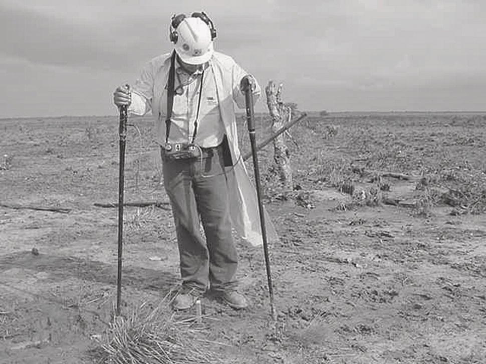
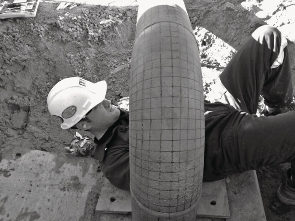
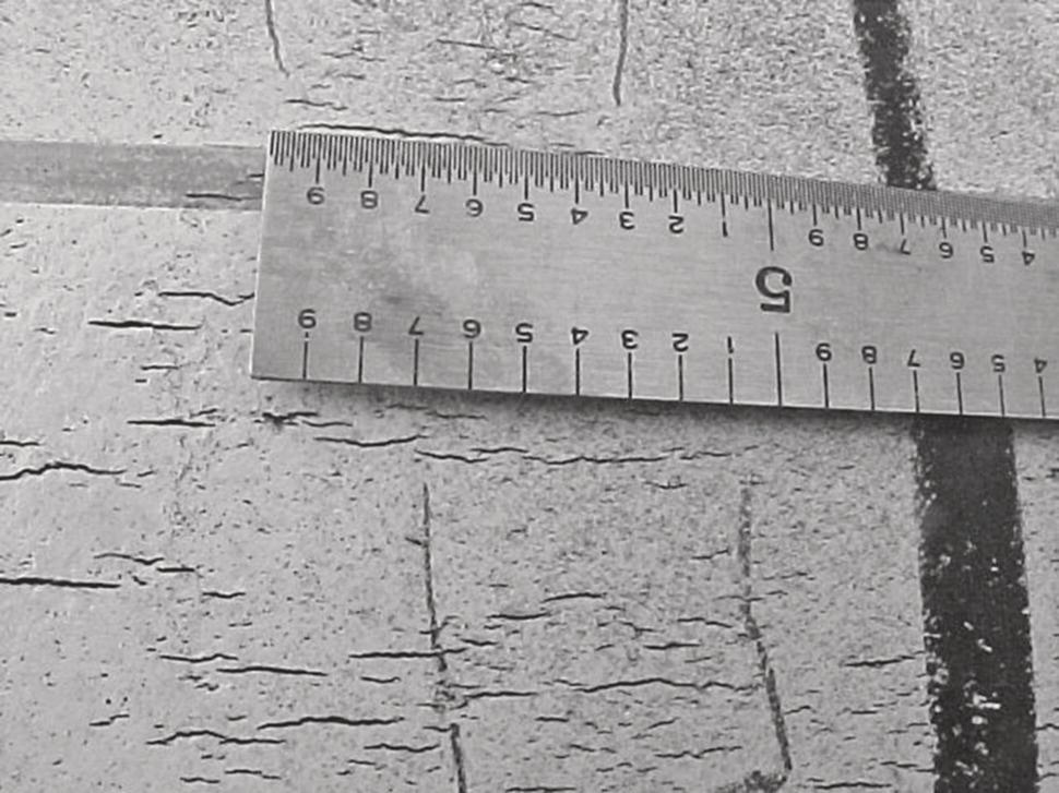
John A. Beavers Lynsay A. Bensman and Angel R. Kowalski DNV, Dublin, OH, USA There are three common techniques used for assessing the integrity of pipelines subject to time-dependent corrosion threats: hydrostatic pressure testing, in-line inspection (ILI), and direct assessment (DA). Each methodology has its strengths and weaknesses and a combination of these methodologies typically provides the most effective integrity management. Hydrostatic pressure testing is the oldest technology used to confirm the integrity of pipelines and prevent future failures. The pipelines are pressure tested with water at pressures significantly higher than the operating pressure in order to remove near critical flaws. Any flaws remaining in the pipeline will be smaller than the critical size at normal operating pressures and, given that the flaw-growth rates are reasonably low, will thus require some time to grow to a critical size. The operator must estimate the growth rate of the flaws remaining in the pipeline in order to establish the retest interval. This growth rate can be estimated based on the prior hydrostatic test history of the pipeline, laboratory research, or the results obtained from ILI or DA. While hydrostatic testing has been effective in reducing service failures, it has a number of limitations. Very few, if any, flaws are removed and the pipeline must be taken out of service for testing. The removed flaws are those that are sufficiently large to cause a rupture at the hydrostatic test pressure. In dry climates, obtaining adequate sources of water can be a challenge while freezing of the water can be an issue in winter months and northern climates. In some pipelines, the addition of water introduces the threat of internal corrosion where previously it did not exist. For liquid petroleum pipelines and some gas pipelines, the water must be treated prior to discharge to prevent the introduction of contaminated water into the environment. A pressure reversal also may occur where the failure pressure after the test is lowered by the hydrostatic test due to growth of flaws during the test. ILI is another technique used to manage time-dependent integrity threats on operating pipelines. There is a long history of using magnetic flux leakage (MFL) and, to a lesser extent, ultrasonic tools to address internal and external corrosion threats on pipelines. Over the past 20 years, there has been significant work performed in the development of ultrasonic crack detection tools. These ILI technologies have a big advantage over hydrostatic testing in that they are capable of detecting flaws that are much smaller than the critical flaws that could fail a hydrostatic test, resulting in longer reinspection intervals than hydrostatic testing. ILI also generally does not require that the pipeline be taken out of service and problems associated with obtaining and handling large volumes of water. However, the pipeline must be capable of accommodating the ILI tools. This requires the presence of appropriate launchers and receivers and the absence of components in the pipeline that would obstruct a tool, such as high angle bends, diameter changes, and certain types of valves. The single biggest issue with ILI technologies is that there is a finite probability that a nearcritical feature will not be detected or will be detected and improperly sized. The technologies for the detection of corrosion flaws are more mature and therefore less likely to miss a near critical defect than those for detection of crack-like defects. Because of these detection and sizing issues, one or more validation methods are typically employed. In some cases, pipeline operators will validate the detection and sizing capabilities of the tool by means of a dig program, where the reported flaw dimensions are compared with the dimensions measured in the field. In other cases, pipeline operators perform confirmatory hydrostatic tests on portions of their system to demonstrate the performance of the ILI tool. Pipeline operators may be faced with a situation where a large number (thousands) of features are found by ILI on a segment of a pipeline. They can use elements of DA, such as those used in the preassessment and indirect inspection steps, in conjunction with sizing of the ILI features, to identify which features are most likely to be an integrity threat and should be excavated. These DA elements are also used to prioritize pipeline systems for ILI. The limitations of hydrostatic testing and ILI have increased interest within the pipeline community in the development of alternatives, such as DA, to these integrity management tools. Elements of DA have always been used in the management of pipeline integrity but the DA procedures have only recently been formalized. DA is somewhat of a misnomer in that the direct inspection or assessment of the pipe is only one, the third, element of the DA process. For the most common DA procedures, there are three other elements or steps: (1) preassessment, (2) indirect inspections, and (3) postassessment. The details of each step can differ significantly for each different type of DA. Formal DA procedures have been developed to address external and internal corrosion threats to both gas and liquid petroleum pipelines. This chapter summarizes these procedures. External corrosion of buried onshore ferrous piping has been identified as a serious threat to the structural integrity around the world. In the United States, a congressional funded research program conducted between 1999 and 2001 [1] determined that the corrosion-related cost to the transmission pipeline industry was approximately $5.4–$8.6 billion annually. The external corrosion direct assessment (ECDA) methodology was developed to assist pipeline operators when evaluating the impact of external corrosion on the structural integrity of buried piping. Pipeline operators have historically managed external corrosion using some of the ECDA tools and techniques. Often, data from aboveground inspection tools have been used to identify areas that may be experiencing external corrosion. The ECDA process takes this practice several steps forward and integrates information on the physical characteristics of a pipeline and operating history with data from multiple field examinations and pipe surface evaluations to provide a more comprehensive integrity evaluation with respect to external corrosion. ECDA is a four-step process that combines preassessment, indirect inspections, direct examinations, and post assessment to evaluate the likelihood of external corrosion on a pipeline. The first recommended practice was issued in 2002 (NACE1 Standard RP-0502-2002 [2]). The standard was reaffirmed in 2008 [3] without significant changes and republished again in 2010 (NACE—ANSI Standard Practice SP0502-2010 [4]). The preassessment step has three main objectives: (1) determine whether ECDA is feasible for the pipeline to be evaluated, (2) select the indirect inspection tools, and (3) identify the ECDA regions. The feasibility of the methodology may be affected by availability of data, conditions for which indirect inspections are not available or cannot be collected, or sections of pipe where visual inspection of the pipe may not be practical or feasible. An ECDA region is a section or sections of the pipeline segment that have similar physical characteristics, corrosion histories, expected future corrosion conditions, and in which the same indirect inspection tools are used. Indirect inspection covers aboveground inspections that help identify and define the coating condition, other anomalies, and areas where corrosion activity may be occurring. The inspection tools include, but are not necessarily limited to, close interval potential survey (CIS), direct current voltage gradient (DCVG), and alternating current voltage gradient (ACVG). An example of a technician performing DCVG measurements to locate coating defects is shown in Figure 27.1. The indirect inspection requires at least two complementary tools to be used over the entire length of each ECDA region, although it is wise to complete as many as are practical. These complementary tools improve detection reliability under the wide variety of conditions that may be encountered along a pipeline segment. After the tests are completed, indications are identified and aligned for comparison. The criterion to establish a classification is determined and the severity of each indication is classified as severe, moderate, or minor. The direct examination step determines which indications from indirect inspections are most severe, and data are collected to assess corrosion activity. Direct examination requires excavations to expose the pipe surface so that measurements can be made on the pipeline and in the immediate surrounding environment. Direct examination of a pipe segment for external corrosion is shown in Figure 27.2. A minimum of one direct examination per ECDA region is required (two per ECDA region when ECDA is applied for the first time on the pipeline segment) regardless of the results of the indirect inspections and preassessment steps. During the direct examination, defects other than external corrosion may be found and should be assessed according to applicable standards and codes. The pipeline operator evaluates or calculates the remaining strength at locations where corrosion defects are found. Figure 27.1 DCVG measurements being performed to locate coating anomalies on an underground pipeline. (with permission of Det Norske Veritas (U.S.A.), Inc.) Figure 27.2 Direct examination of a pipe section. Ultrasonic wall loss measurements are being performed at the center of each grid square. (with permission of Det Norske Veritas (U.S.A.), Inc.) During postassessment, analyses of data collected from the previous three steps are conducted to assess the effectiveness of the ECDA, identify existing root causes of external metal loss identified and determine reassessment intervals. The reassessment interval may be defined as half of the remaining life of the piping system based on remaining indications not mitigated during the process. The estimate of remaining life is based on conservative growth rates and conservative growth periods. Some of the advantages of ECDA are as follows: (1) it is not an intrusive method as it does not require interruption of pipeline operation, (2) it is an alternative assessment methodology for pipelines that cannot be inspected by ILI, (3) it identifies the direct cause of external metal loss due to corrosion, and (4) it may be used as a complementary assessment to improve results of ILI and hydrostatic testing. Some of the limitations of ECDA are as follows: (1) the effectiveness and feasibility of DA are based on the amount and quality of relevant data, (2) it may not be feasible for pipelines susceptible to electrical shielding, (3) it may not be cost effective when indirect inspection is limited by external conditions that require additional activities such as drilling, and (4) excavation of the pipeline for direct examination may not be practical or feasible due to associated risks. Under AMPP, the ECDA standard is under review by the Standard Committee (SC) 15 Pipelines and Tanks. No new ECDA standard has been published after NACE SP0502-2010. As already discussed, the task group working on the standard is incorporating lessons learned from experience to improve the effectiveness of the methodology. One aspect being analyzed at the present time is the incorporation of new guidelines to assess the integrity of pipeline sections located in steel casings. There is also interest in providing more guidance to pipeline operators on how to address the ECDA feasibility when required data are not available. Future ECDA improvements will most likely come from innovation in technologies associated with predictive capabilities of indirect inspections and also with overcoming existing limitations related to electrical shielding and cased pipe sections. The first recognized stress corrosion cracking (SCC) failure of an underground pipeline occurred in 1965 in Natchitoches, Louisiana [5]. The SCC associated with this failure was intergranular in nature (the cracks followed the grain boundaries in the metal) and is referred to as high-pH or classical SCC (HpH SCC). A second form of external SCC was discovered in the 1980s [6]. This form of SCC is referred to as near-neutral pH SCC (NNpH SCC) and is transgranular (the crack path is through the grains in the metal). Both forms of cracking are associated with crack colonies that may contain up to thousands of cracks. The cracks most typically are axially oriented but may be at other orientations depending on the nature of the stresses in the pipelines. In some cases, growth and interlinking of the stress corrosion cracks produce flaws of sufficient size to cause leaks or ruptures of the pipelines at normal operating pressures. The first recommended practice for Stress Corrosion Cracking Direct Assessment (SCCDA) was issued in 2004 (NACE Standard RP0204-2004) [7]. The standard was reaffirmed in 2008 without significant changes [8] and was revised in 2015 [9]. SCCDA is a structured process that is intended to assist pipeline companies in assessing the extent of SCC on buried pipelines and thus contribute to their efforts to improve safety by reducing the impact of external SCC on pipeline integrity. The term is somewhat of a misnomer in that the process is much more extensive than simply examining the pipeline for evidence of SCC. SCCDA is a four-step process; preassessment, indirect inspections, direct examinations, and postassessment. The preassessment step involves the collection of existing information on the pipeline that can be used to assess the likelihood that the pipeline is susceptible to SCC, prioritize sections of the pipeline for examination, and select dig sites. In the indirect inspection step, aboveground or other types of measurements are conducted to supplement the data obtained from the preassessment. This could include CIS data, coating fault survey data, or geological information. In the direct examination step, the pipe is examined to assess the presence, extent, type, and severity of SCC. An example of a colony of stress corrosion cracks found during direct examination is shown in Figure 27.3. Other information, such as coating condition, soil information, or electrolyte composition, can also be collected. The information that is required to be collected in the direct examination step of the SCC DA process is data necessary to confirm the integrity of the pipe segment examined. This includes the pipe diameter, wall thickness, seam weld type, location and size of SCC colonies, results of crack length and depth measurements, and the identification and sentencing of any other defects found on the pipe segment. In the postassessment step, remedial actions, if required, are identified and prioritized, reassessment intervals are defined, and the effectiveness of SCCDA is evaluated. Figure 27.3 Colony of stress corrosion cracks found during the DA step of SCCDA. The cracks were revealed by magnetic particle inspection of the external surface of the pipe. (with permission of Det Norske Veritas (U.S.A.), Inc.) Table 27.1 [9] summarizes important factors that should be initially considered in ranking susceptible valve segments of a pipeline and in the selection of dig sites. The information in this table considers pipe related, construction related, soil/environmental related, and corrosion control related factors and pipeline operational data and is based on laboratory and field research performed over the past 50 years on SCC. The first recommended practice for SCCDA, RP0204-2004 [7], adopted the criteria found in the 2004 version of ASME B31.8S [10)] for the selection of pipeline segments that have the highest likelihood of containing SCC colonies. In the case of HpH SCC, the initial selection of susceptible segments is based on five factors: operating temperature (>100 °F), operating stress (>60% of the specified minimum yield strength), distance from compressor station (<20 miles), pipeline age (>10 years), and coating type other than fusion bonded epoxy (FBE)] [10]. The 2004 version of ASME B31.8S [10] only addressed high-pH SCC. RP0204-2008 [8] used the same criteria for the selection of NNpH SCC susceptible segments but removed the temperature criterion. The 2010 version of ASME B31.8S [11] excludes both the temperature criterion and the distance criterion for NNpH SCC. The distance parameter is somewhat redundant in that it is generally thought to incorporate the stress effect, as well as the temperature effect, in the case of high-pH SCC. Table 27.1 Important Factors for Consideration in Ranking Susceptible Segments and in site Selection for SCC; Condensed from Reference [9] Source: [9]/with permission of NACE International. A: major factor; B: factor having some effect In the most recent version of the SCCDA Standard Practice, SP0204-2015 [9], primary guidance for assessing and managing the structural integrity of natural gas pipelines that have a risk of containing stress corrosion cracks was adopted from ASME B31.8S, Appendix A3 [11], which identifies several options for assessment and mitigation. The CEPA Stress Corrosion Cracking Recommended Practices [12] is recommended in the NACE SCCDA SP [9] for additional guidance for managing the structural integrity of natural gas and liquid petroleum pipelines subject to NNpH SCC. When applying guidance found in these documents to liquids pipelines, the potential for fatigue and or corrosion fatigue must be considered in order to establish appropriate assessment intervals and mitigation activities [9]. For complicated pipeline systems, the preassessment phase of SCCDA can be used to eliminate SCC as a significant integrity threat, allowing operators to focus their efforts on portions of the system where SCC is likely to occur. Where it has been determined that SCC is a serious threat, carrying out SCCDA is complementary to ILI and hydrostatic testing. As already discussed, it can be used to prioritize segments for ILI or hydrostatic testing. For validation of an ILI run, SCCDA can be used to identify which ILI indications are most likely to be caused by SCC and require excavation. Appendix A3 of ASME B31.8S [10, 11] (both versions) states that each pipeline segment should be assessed for risk for the possible threat of SCC if all of the relevant criteria are present, implying that SCC is not an integrity issue for segments that do not meet these criteria. Batte [13] reviewed the service experience of the gas transmission pipeline industry from the mid-1960s through 2010. It was found that between 80 and 90% of SCC failures met all of the relevant criteria; thereby, demonstrating the importance of these parameters in the SCC process. On the other hand, this is not adequate performance for an integrity management program that relies solely on SCCDA. The authors of NACE RP0204-2004 [7] recognized this issue and included wording in the standard to state the following. “It is recognized that these screening factors will identify a substantial percentage of the susceptible locations, but not necessarily all of them.” In other words, the criteria are great for selecting the most susceptible sites for SCC but will not find all of them. Therefore, a significant limitation of SCCDA is that it is presently not capable of reliably identifying the location or locations of the most severe SCC on a pipeline segment. Perhaps, the predictive capability of SCCDA will improve with better techniques and or understanding of the phenomenon. However, at the present time, it is not always a suitable replacement for hydrostatic testing or ILI. The preassessment step of SCCDA may indicate that a particular pipeline segment is not likely to be susceptible to SCC, and, therefore, other threats are of a more immediate concern. An example would be a newer pipeline with an FBE coating. At the other extreme, ILI, hydrostatic testing, or even pipe replacement may be warranted if extensive, severe, SCC is found. On this basis, SCCDA is currently better suited as a threat identification tool than for integrity verification. The last update of SP0204 was published in 2015 [9], and the standard currently is due to be updated based on industry experience with the standard over the past 10 years, changes to referenced standards, and new findings from applied research. As already discussed, SCCDA, in its current form, is better suited as a threat identification tool than for integrity verification because it is presently not capable of reliably identifying the location or locations of the most severe SCC on a pipeline segment. For pipelines where SCC has been identified as a major threat, SCCDA can be used to prioritize segments for ILI or hydrostatic testing and to assist in the selection of dig sites for verification of ILI. It is unlikely that, in the near future, technology will change to the extent that SCCDA will be capable of locating the most severe or all SCC on a pipeline segment. This is primarily the result of the inability of the indirect tools used to address the issue of the variation in SCC susceptibility of individual pipeline segments. These tools typically are used to look for evidence of coating damage or cathodic protection (CP) levels. Major changes to the standard will likely address any recent changes to ASME B31.8S [11] with respect to severity categories. For example, in the earlier versions of the ASME document [10] and the CEPA Recommended Practice [14], there were two SCC severity categories (significant and not significant) and the number of these categories was expanded in the later documents. All pipeline systems can be susceptible to internal corrosion. Even “dry” gas transmission lines can suffer from internal corrosion as a result of upsets at upstream gas processing facilities or the transportation of gas that does not meet quality specifications designed to prevent water condensation. The concept of internal corrosion direct assessment (ICDA) was first formalized in 2002 [15] and was developed based on existing technologies, namely, modeling techniques, to evaluate and assess internal corrosion. The original concept behind ICDA for gas transmission lines was that examination of locations where water is expected to accumulate allows conclusions to be drawn regarding the remaining portions of a pipeline. The first NACE ICDA standard for dry gas ICDA (DG-ICDA) was issued in 2006 [16], followed by liquid petroleum ICDA (LP-ICDA) in 2008 [17], wet gas ICDA (WG-ICDA) in 2010 [18], and multiphase flow ICDA (MP-ICDA) in 2016 [19]. The preassessment step involves the collection of data that can be used to determine the feasibility of performing ICDA, identify locations of potential water input, and perform flow modeling and corrosion rate modeling/factor analysis. The indirect inspection step involves performing flow modeling in order to determine the location of expected water and/or solids accumulation as well as corrosion rate modeling/factor analysis in order to select locations for examination. In the direct inspection step, which is often referred to as the detailed examination step for ICDA, the pipe is inspected for the presence, extent, and severity of internal corrosion. Nondestructive testing methods are utilized as the internal surface of the pipe cannot be visually examined while the pipeline is in service. In the postassessment step, remedial actions, if required, are identified and prioritized, reassessment intervals are defined, and the effectiveness of ICDA is evaluated. The particulars for how the indirect inspection step is executed are different for each ICDA method and are discussed as follows. Dry gas ICDA operates under the premise that examination of the furthest downstream locations where water is expected to accumulate allows inferences to be made regarding the integrity of the remaining downstream sections of the pipeline. In the indirect inspection step, the critical inclination angle past which water is not expected to flow is calculated. At pipeline inclinations less than the critical angle, the forces exerted by gas movement overcome the force of gravity acting on the water and cause the water to be transported through the pipe. At inclinations greater than or equal to the critical angle, the force exerted by gravity overcomes the force exerted by gas flow and the water is expected to “holdup” or accumulate. The highest velocity experienced by the pipeline (or other combination of velocity and pressure that yields the greatest critical inclination angle) is used to select the furthest downstream location to which water could have been transported. Two locations downstream from this point are also inspected as confirmation that there is no corrosion downstream from the furthest location where water could have been transported. If internal corrosion is found downstream of the initial site, then either a higher velocity has occurred than the velocity utilized in the critical angle calculation or the pipeline operated outside of a “normally dry” environment at some point historically. In order to account for periods of lower flow, upstream (or subregion) inspections are also performed. If internal corrosion is found at any of the inspection locations, additional inspections are required. Thus, this method is not applicable to pipelines on which extensive internal corrosion is present. Wet gas ICDA operates under the premise that the pipeline is continuously wet and therefore focuses on the differentiation in predicted wall loss due to internal corrosion. In the indirect inspection step, flow modeling is performed in order to identify where different flow regimes are expected to occur and liquid hold-up volumes are estimated for locations where accumulation is predicted. Corrosion rate modeling is then performed to estimate the corrosion wall loss that has occurred during the service life. Multiple scenarios may need to be modeled in order to account for different internal environments that existed during the service life. The number of inspections performed is then determined based on the total length of pipeline being assessed and the predicted wall loss. Success of the WG-ICDA process is determined by comparison of the results found during the detailed examination step versus what was predicted during the indirect inspection step. Similar to DG-ICDA, liquid petroleum ICDA is intended to identify locations along the pipeline where water may accumulate. Liquid flow modeling is utilized to determine whether or not water will remain entrained within the liquid hydrocarbon product being transported or will separate out into a separate layer (this separation is referred to as stratified flow). Solids flow modeling is also performed to identify whether solids accumulation is expected to occur. Factor analysis, which considers how different factors impact the corrosion rate and thus corrosion distribution within the pipeline, is used to identify which accumulation locations are most likely to experience internal corrosion. Alternatively, corrosion rate modeling may be utilized to prioritize locations. Inspections are performed at locations where water and solids accumulation is predicted. Again, similar to DG-ICDA, additional inspections are required if internal corrosion is found. Thus, this method may not be applicable to pipelines in which extensive internal corrosion is present. Similar to WG-ICDA, multiphase flow ICDA is intended to predict the expected wall loss along the length of the pipeline and then perform detailed examinations at various locations to confirm the predicted wall loss. MP-ICDA is intended for pipelines that transport gas, water, solids, and/or crude oil or hydrocarbon liquids during normal operation. In the indirect inspection step, multiphase flow modeling is performed to determine the flow pattern as well as pressure and temperature profiles, water hold-up, and gas and liquid velocities along the length of the pipeline. Subregions are then identified, based on flow patterns, and corrosion severity (i.e., wall loss) is predicted within each subregion. The number of inspections performed is then determined based on the total length of pipeline being assessed and the predicted wall loss. If the results of the identified wall loss from the detailed examination step do not corroborate what was predicted during the indirect inspection step, additional inspections are required. Both DG-ICDA and LP-ICDA are best suited for long pipelines with limited numbers of inputs because direct examination requirements are set per region (and new regions are set for each input location). For networks or systems with multiple inputs, DG- or LP-ICDA can quickly become economically unfeasible to perform. ICDA techniques can be incorporated into overall internal corrosion management programs in order to identify pipelines that are more susceptible to internal corrosion or to select locations for installation of monitoring devices. Historical information is crucial to the success of ICDA. Multiple data inputs are needed to perform flow modeling and corrosion rate modeling (where needed). The modeling is intended to be performed on the most severe conditions experienced from an internal corrosion standpoint or for a sufficient number of conditions experienced to fully represent the history of the segment. While it is possible to collect data regarding current conditions; for older pipelines, these data may not sufficiently represent historical conditions. In such cases, it is possible to draw erroneous conclusions based on the limited number of detailed examinations performed. In addition, it is generally more difficult to accurately predict locations where solids accumulation will occur because less information tends to be available regarding the volume and composition of solids being transported. One final note from a corrosion rate modeling perspective; widely accepted models that predict the rate and location where microbiologically influenced corrosion (MIC) is expected to occur have not yet been developed. Because MIC is known to be a prevalent internal corrosion threat, which can cause very high internal corrosion rates, this can be a significant limitation for systems in which MIC is occurring. The entire suite of internal operating environments has been addressed through the existing four standards. AMPP maintains and updates the standards, as necessary. Additional AMPP documents have been developed related to corrosion rate and flow modeling that support the ICDA standards [20, 21]. ICDA can be used as a standalone integrity management technique and is routinely used as such, mainly in nonpiggable pipelines. However, it is also an excellent tool to use in conjunction with ILI in order to better understand why internal corrosion is occurring at certain locations. ICDA usage continues to grow, especially outside the United States. As users gain experience with the techniques, improvements will undoubtedly continue to be made in the process. In addition, as improvements continue to be made for both flow and corrosion rate modeling techniques, the ICDA methodologies will continue to increase in accuracy.
27
Direct Assessment
27.1 Introduction
27.2 External Corrosion Direct Assessment
27.2.1 Overview of Technique/Standard
27.2.2 Strengths
27.2.3 Limitations
27.2.4 Status of Standard
27.2.5 Context of Technique/Standard in Integrity Management
27.2.6 Where ECDA Technique is Headed
27.3 Stress Corrosion Cracking Direct Assessment
27.3.1 Overview of Technique/Standard
Factor
Relevance to SCC
Use and Interpretation of Results
Ranking
Pipe Related Factors
Pipe manufacturer
NNpH SCC found preferentially in heat affected zone (HAZ) of electric resistance welded (ERW) line pipe from one pipe manufacturer. Reported to be statistically significant predictor for NNpH SCC for one pipeline system.
Important factor for NNpH SCC.
A
Seam type
NNpH SCC found under tented tape coatings along double submerged arc welded (DSAW) seams and in ERW seams. No known correlation with HpH SCC.
Important factor for NNpH SCC.
B
Surface preparation
Grit blasting can be beneficial in mitigating SCC by introducing compressive residual stresses at the pipe surface and removing mill scale.
Important factor for both forms of SCC.
A
Coating type
SCC has not been reported, to date, with undamaged fusion bonded epoxy (FBE) coatings. HpH SCC is found under coal tar, asphalt, and tape coatings. NNpH SCC is most prevalent under tape coatings but is also found under other susceptible coating types.
Important factor for both forms of SCC.
A
Bare pipe
SCC had been observed on bare pipe in high-resistivity soils.
May be important factor.
B
Hard spots
NNpH SCC has been observed in hard spots.
May be important factor.
B
Construction Related Factors
Year installed
Time required for coating to degrade, cracking environment to develop, and cracks to initiate and grow.
Age of pipeline used in criteria for selection of susceptible segments in Part A3 of ASME B31.8S [10].
A
Construction practices
Backfilling practices influence coating damage during construction. Time between burying of pipe and installation of cathodic protection (CP) affects pipe-to-soil potentials.
Early CP levels might be important.
B
Weights and anchors
NNpH SCC has been found under buoyancy control weights.
May be important factor, especially for NNpH SCC
B
Casings
CP shielding and coating damage more likely in casings.
May be important factor.
B
Bends
Increase residual stresses.
May be important factor, especially for NNpH SCC.
B
Dents
Increase residual stresses.
May be important factor, especially for NNpH SCC.
B
Soil/Environmental Related Factors
Soil characteristics
Some evidence that high sodium or potassium concentrations may promote development of HpH SCC environment. Some success in correlating NNpH SCC with specific soil types.
May be important factor.
B
Drainage
Has been correlated with both forms of SCC.
May be important factor.
B
Topography
Has been correlated with both forms of SCC. Circumferential SCC has been observed on slopes where soil movement has occurred.
May be important factor.
B
Land use (current/past)
No correlations have been found, but use of fertilizer may affect groundwater and trapped water chemistry under coatings.
May be important factor.
B
Soil/groundwater resistivity
Soil resistivity affects throwing power of CP systems.
May be important factor.
B
River crossings
Affects soil moisture/ drainage.
May be important factor.
B
Soil CO2 concentrations.
CO2 dissolved in groundwater associated with both forms of SCC.
May be important factor.
B
Corrosion Control Related Factors
CP system type (impressed current versus sacrificial anode)
Adequate CP at pipe surface can prevent SCC, but overprotection from impressed current CP systems can promote generation of HpH SCC environment.
Important factor.
B
CP shielding
CP shielding commonly associated with NNpH SCC.
Important factor.
B
Close interval survey (CIS) and test station data
HpH SCC occurs in a relatively narrow potential range between typical corrosion potentials and potentials for adequate protection. NNpH SCC occurs near typical corrosion potentials. Locations of crack colonies may correlate with CP history.
Important factor.
B
Coating Fault Survey Data
SCC occurs at coating faults where groundwater has access to the pipe surface.
Important factor.
B
Pipeline Operational Data
Pipeline operating temperature
Elevated temperature can contribute to coating degradation and promote HpH SCC.
Important factor, especially for HpH SCC.
A
Operating stress and stress fluctuations.
Tensile stress must be above threshold for SCC and stress fluctuations lower the threshold and increase crack growth rates. Critical flaw size is inversely proportional to stress level.
Important factor.
A
SCC leak/rupture history
High probability of finding SCC in the vicinity of previous in-service and hydrotest SCC failures.
Important factor.
A
Direct inspection and repair history
High probability of finding SCC in the vicinity of previously discovered SCC.
Important factor.
A
ILI data from crack detection tools
High probability of finding SCC in the vicinity of previously discovered SCC.
Important factor.
A
ILI data from crack metal loss tools
NNpH associated with regions of coating disbondment and superficial external corrosion.
May be important factor for NNpH SCC.
B
Product type
Lower probability of HpH SCC on liquid pipelines because of lower operating temperatures (except for heated products).
May be important factor for HpH SCC.
B
27.3.2 Strengths
27.3.3 Limitations
27.3.4 Status of Standard
27.3.5 Context of Technique/Standard in Integrity Management
27.3.6 Where SCCDA Technique is Headed
27.4 Internal Corrosion Direct Assessment
27.4.1 Overview of Technique/Standard
27.4.2 Dry Gas ICDA
27.4.3 Wet Gas ICDA
27.4.4 Liquid Petroleum ICDA
27.4.5 Multiphase Flow ICDA
27.4.6 Strengths
27.4.7 Limitations
27.4.8 Status of Standards
27.4.9 Context of Technique/Standard in Integrity Management
27.4.10 Where ICDA Technique is Headed
References
Note