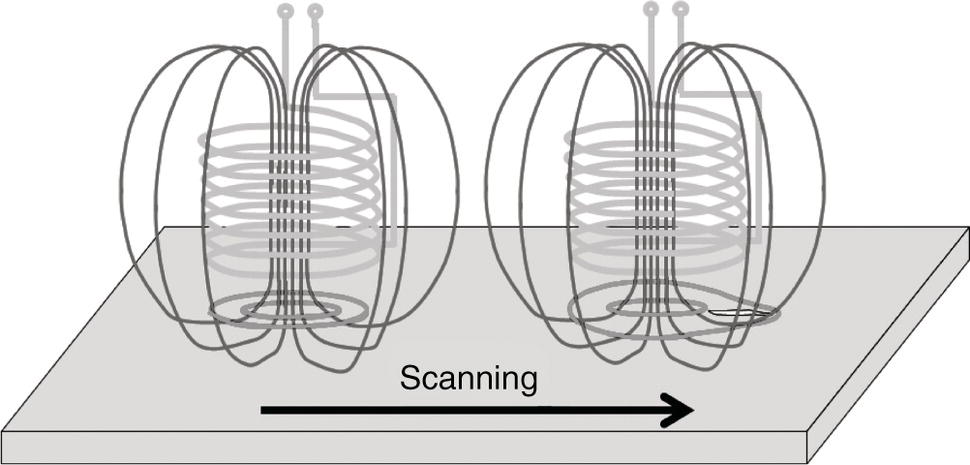
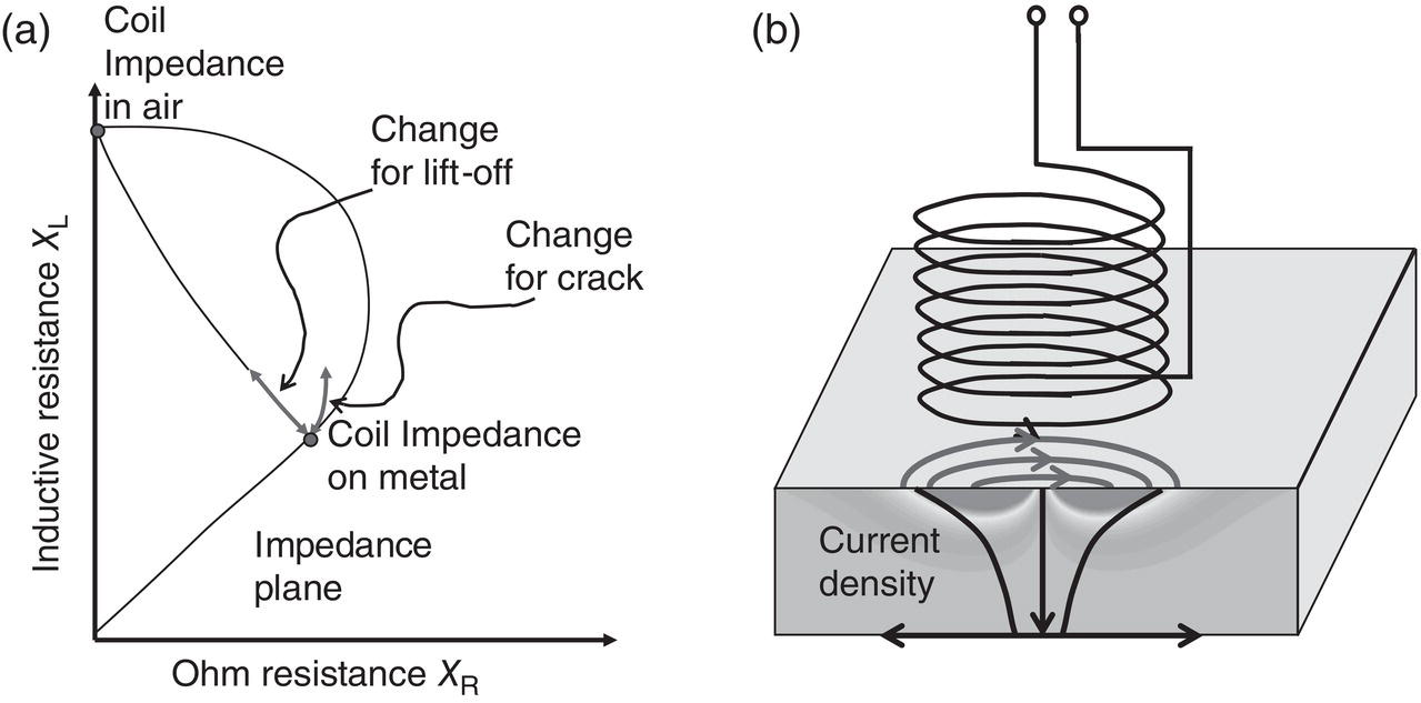
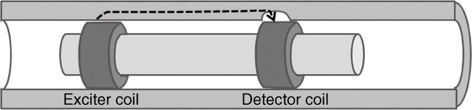
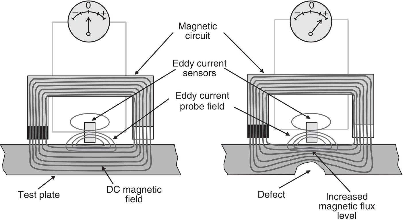
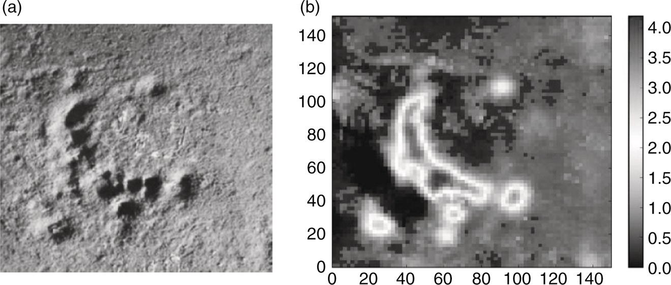
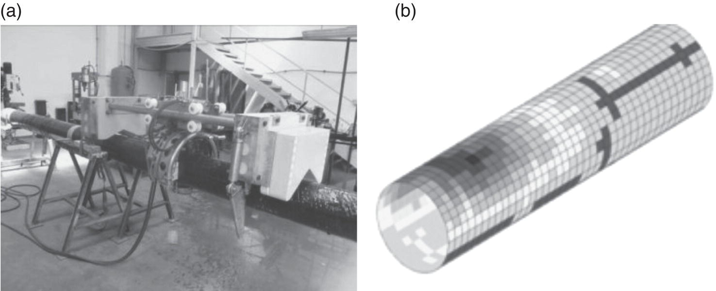
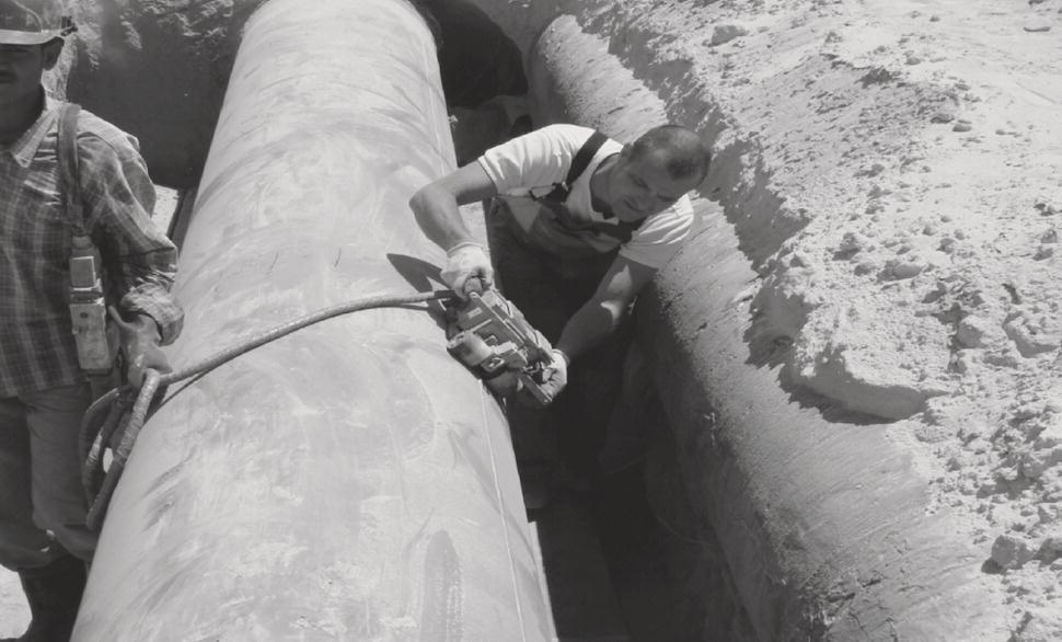
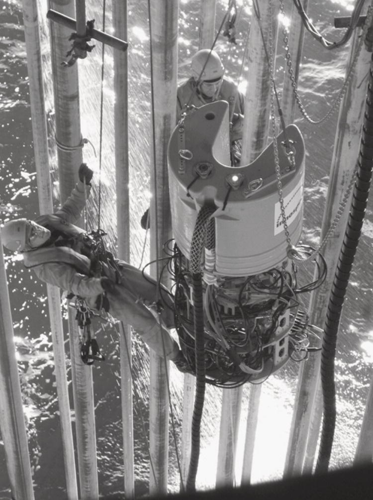
Konrad Reber Innetiqs GmbH, Stutensee, Germany The basis for eddy current testing (ECT) was laid by the discoveries of electromagnetic effects in the nineteenth century. The protagonists were Michael Faraday (1791–1867) for the discovery of the interaction between magnetic fields and electrical currents and Leon Foucault (1819–1868) for the discovery of eddy currents in metal objects. Only the sound electromagnetic theory developed by James Clerk Maxwell (1831–1879) allows us to engineer circuits and probes today for inspection. The tribute for the first application of eddy currents is given to David Edward Hughes (1830–1900) for metal sorting. Friedrich Foerster (1908–1999) developed the first devices for ECT as we know them today. Eddy current inspection developed into a major branch of nondestructive testing (NDT). Although it is limited to conductive materials, the possibility to automate the scanning and signal analysis has increased its importance since it was introduced. As will be described in the following section, its role in pipeline inspection is minor today, although recent developments suggest that this is currently changing. The basic principle of ECT consists of measuring the impedance of an electrical coil. The impedance is its complex resistance, which also depends on a property called inductance. The inductance is a physical property of a coil that describes how a magnetic field is generated, when an electrical current is sent through it. Electromagnetic theory shows that the effect of inductance leads to a phase shift and amplitude change in the current, when an AC voltage is applied to the coil. The inductance of a coil can, thus, be measured by measuring its AC resistance (impedance). It depends on the size of the coil, the number of turns, and most importantly on the electromagnetic properties of all materials in the vicinity of the coil. A coil in the vicinity of a metallic surface will have a different impedance as compared to the same coil in air. Moreover, a coil close to a metallic surface will have a different impedance depending on whether the metallic surface is flawless or has a crack. This is the basis of ECT. To understand the capabilities and limitations of ECT better, a few more details are required. The details of the setup are shown in Figures 32.1 and 32.2. An AC current flows through a coil. An AC magnetic field is generated around the coil. If the coil is in air, the magnetic field depends only on the nature of the coil (its inductance). If the coil is brought closer to a metallic surface, the magnetic field will penetrate the metal piece. According to the law of electromagnetic induction, an AC magnetic field will lead to the generation of currents in the surface. These currents generate a magnetic field that, according to Lenz’s Law, is opposed to the initial field. It weakens the original field and thus influences the inductance of the coil. Anything that changes the nature of the eddy currents in the metal can, thus, be detected by a change in the impedance. Naturally, the vicinity of the coil to the surface and the presence of a crack in the metal are such influences on the eddy currents. The deeper the crack, the more it will impede the flow of currents in the surface and the higher the effect. It lies in the nature of electromagnetic induction that the currents flow in the surface only (skin-effect). The degree to which they will penetrate the bulk of the material depends on the material properties. Electromagnetic theory shows that the higher the frequency of the currents and the higher the conductivity and permeability of the metal, the more the currents will be confined to the surface. Standard eddy current techniques employ a frequency of a few kHz to MHz. This means that stainless steel tubes of a few mm wall thickness can be inspected, while on carbon steel tubes, only surface effects are detected. The effect of limited penetration depth is shown on the right of Figure 32.2. Figure 32.1 The concept of eddy current testing. The coils used for inspection vary considerably in size, shape, and design. Either single coils (absolute coil) or two coils in a bridge mode (differential coil) can be used. The latter makes the arrangement very sensitive to sudden changes, while the first is more suitable for the detection of gradual changes in material properties. Also, coils can be arranged in a send–receive setup (reflection mode). In general, it can be said that the smaller the defect to be detected, the smaller the coil should be and the closer it should be to the surface. The instrumentation itself then consists of a scanner that holds sensors in a predefined distance to the surface (lift-off) and allows moving them smoothly in a certain direction. An electronic data acquisition system carries out a phase-sensitive detection to determine the complex impedance. The value of the impedance is shown in the impedance plane (the left of Figure 32.2) as a point. As the sensor moves over a surface, the locus point, i.e., the position of the point on the impedance plane moves, when the impedance changes. Eddy current sensing technology has widespread application in the aviation industry. Here, the detection of cracks in riveted joints is of paramount importance. As the material to be tested is aluminum and the sheets are rather thin, ECT has been the method of choice for many years now. Also, ECT is applied in all kinds of component testing. Another application is material sorting, which makes use of the fact that different metals have different conductivity values. The application of ECT in the oil and gas industry and, in particular, for pipeline inspection is so far of minor importance. The task in pipeline inspection involves finding cracks and corrosion in a comparatively thick-walled pipe, which is always produced from low-carbon ferritic steel (exceptions are described in the following section). Also, far-side defects need to be detected, i.e., for internal inspection (pigging), external corrosion defects are of interest. With the limitation in penetration depth, none of these tasks can be achieved with standard eddy current technology. In summary, it can be said that standard eddy current testing in pipeline inspection is rather used to complement other techniques. The most often applied technique consists of measuring the stand-off of a probe from a surface. This allows for profiling the near-side surface. Altogether, three methods can be identified that use an alteration of the standard eddy current idea and are frequently used in the oil and gas industry. It is a matter of viewpoint whether these methods should be called eddy current technology. Nevertheless, all of these techniques employ an AC-electromagnetic method and are commonly referred to as “eddy current” techniques. These methods comprise remote field eddy current testing (RFEC) and the closely related low-frequency eddy current testing (LFET), pulsed eddy current technology (PEC), and magnetic eddy current testing (SLOFEC™, MEC™, or MagControl™). SLOFEC™ stands for saturation low-frequency eddy current and MEC™ for magnetic eddy current. A commonly used generic term is “partial saturation eddy current” or “magnetic biased eddy current”. Figure 32.2 (a) The change of the locus point in the impedance plane will indicate defects. (b) The depth of penetration of eddy currents into the metal is limited. The main idea about remote field eddy current testing (RFEC) is that it uses very low frequencies. Very low in this context means frequencies in the range of 10–50 Hz. At these frequencies, currents and magnetic fields are no longer confined to the surface. If an exciter coil is placed inside a ferritic tube, a characteristic distribution of eddy currents and magnetic fields will be established. The tube conducts these fields along the axis. If detector coils are placed at a certain distance, the received signal will depend on the quality of the transmission path. Metal loss defects or cracks impeding the flow of eddy currents or magnetic flux will influence the signal. The setup is shown in Figure 32.3. The detector coils need to be placed at a certain distance to avoid any direct coupling with the exciter coil. This coined the name “remote field.” In the early days of RFEC, the working principle was not so evident but has been explored and developed through experimental studies. Today, the interaction principle is well-understood [1]. The key is the distribution of the magnetic field. The magnetization is in the axial direction of the tube or pipe. This reduces the interaction with defects oriented along the axis of the pipe, such as axial cracks. Magnetic flux leakage (MFL) technologies suffer from the same drawback. Closely related to RFEC is a technique called low frequency eddy current testing (LFET). Here also, low frequency magnetization processes are used. The technology is used for external inspection of piping. The typical cylindrical symmetry is not present, which determines the spacing between the sending and receiving coils. Special send–receive configurations are required [2]. External pipe and tank floor scanners based on this technology are available. Figure 32.3 The idea of remote field eddy current testing. The development of the pulsed eddy current (PEC) technique and its application to the oil and gas industry was driven by Shell Global Solutions [3]. The idea is to use a short pulse of current and investigate the response over time. A pulse contains a broad spectrum of frequencies. The lower frequency range will lead to eddy currents propagating through the pipe wall. The speed of this propagation is given by material properties and can be described as a diffusion process. Due to the limitation in wall thickness, the response will show a change in signal once the eddy currents have diffused through the wall. The principle is shown in Figure 32.4. The left shows a steep, broadband, excitation pulse. The resulting eddy currents diffuse through the wall and lead to a delayed response in the coil. The right shows the response on a logarithmic scale. The response originates from deeper and deeper layers of the metal with increasing time. The limitation of the metal sheath thickness shows up as a sudden change in the decay rate of the response. The higher the wall thickness, the later this change-over will occur. The advantages and difference to the other mentioned techniques are that it can deliver absolute wall thickness readings. It is, thus, suitable for a monitoring application, where a stationary sensor measures wall thickness over a long period of time. A drawback is that because of the use of a broader frequency band, a single measurement takes too much time to use PEC on a scanning tool. The sensor needs to be at rest when a measurement is done. The available sensors are made such that larger lift-off values are permissible for the measurement. A measurement through several millimeter and even centimeter of coating is possible. At the same time, the measured wall thickness is an average over the active area of the sensor. Today, service companies can obtain licences to use this technology or purchase corresponding equipment. Refer to Section 32.3.3 for applications. The inability to use standard eddy current techniques on the ferritic pipe material is due to its high values of permeability. This limits the depth of penetration and the obtained information to the near-side surface only. However, far-side defects can influence the near-side response of eddy current sensors. If a pipe wall is magnetized, the magnetic flux distribution will be distorted by the presence of a crack-like or metal loss defect. The distortion of the magnetic flux leads to a higher level of magnetization on the near side of the pipe wall. This concept is shown in Figure 32.5. Figure 32.4 (a) In pulsed eddy current testing, a pulse or step generates eddy currents in the material; (b) the decay of the response is analyzed on a logarithmic scale. The different level of magnetization can be detected with a regular eddy current sensor. At the same time, near-side defects are detected by the regular eddy current effect. In the impedance plane, the two effects can be easily distinguished by analysis of the signal phase. It is important to understand the difference between magnetic eddy current testing and magnetic flux leakage (MFL). The setups of the two methods look quite similar. However, MFL requires a leakage field to be measured. The method senses on the surfaces of the pipe wall. For a repeatable signal in MFL, the magnetizing field requires a rather high level [4]. A value of about 10 kA/m is considered a minimum [5]. In magnetic eddy current testing, a field of 3 kA/m is usually sufficient. The requirement for a minimum magnetization level is due to the need to discriminate other permeability-related signals. Pipeline stresses or material inhomogeneities may be an interesting aspect for inspection. However, a clear distinction of metal loss defects is required. In the early days of in-line inspection (ILI), a need for the detection of internal cracks was deemed to be necessary. Pipelines under cyclic loading may suffer from fatigue. Fatigue cracks may develop from the internal surface as tensile stresses in cylindrical pressure vessels are slightly higher on the inside of the wall. A pig has been developed to find internal cracks using eddy current-based sensing technology [6]. This tool employed a special PEC-technology. The purpose of the pulsation here was to limit power consumption and data storage requirements. The project was discontinued mainly because the need to find internal cracking today is considered to be less important as compared to finding stress corrosion cracking (SCC) on the external pipe surface. Also, for liquid pipelines, a method based on pulse-echo ultrasonic testing (UT) is available. Today, there is no ILI tool based on eddy-current technology alone. With the advent of hydrogen transportation in regular carbon steel pipelines and the medium-related degradation mechanisms, the need for such an inspection may need to be reconsidered. It is now well-understood that the presence of hydrogen increases the susceptibility to crack formation and corresponding codes have been adjusted [7]. Figure 32.5 The principle of magnetic eddy current. Eddy current sensing is, however, employed in regular in-line inspection to complement other technologies. In regular ILI using MFL, a special sensor is required to determine whether a signal originates from the near or the far-side of a pipe wall. Traditionally, a magnetostatic reluctance measurement was used. The problem was that this measurement interferes with the strong magnets of the standard MFL measurement. One ILI provider uses eddy current sensors to measure lift-off and metal loss at the position of an internal defect [8]. This type of corrosion is sometimes called SIC (shallow internal corrosion). If no signal is found, the potential corrosion site is external and vice-versa. However, more than a simple yes/no information can be derived. A calibration allows for converting the signal to the corrosion depth. Figure 32.6 shows a near-side corrosion defect. The left shows the picture of the defect and the right the quantitative measurement by an ILI tool. A similar technology can be used to complement an EMAT sensing technology [9]. For external inspection of pipelines, the mapping of general corrosion is important. This is often done to verify the results of ILIs. Before making a decision on the severity of a corrosion site, a complete mapping of the area is done. One commercial system is based on sheets consisting of an eight-by-eight array of eddy current sensors [10]. The sheet is conformable to allow placing it onto any pipe radius. Through lift-off measurement, a profile of the defect under the array is obtained rapidly. An advanced form of this system has been given the name MWM™ (meandering winding magnetometer) [11]. Another application of standard eddy current technology relies on its capability to distinguish metals with different conductivity. Pipe joints within a pipeline rarely differ in their material alloys. However, there are small changes in conductivity of the steel with respect to the material grade. Higher steel grades often have smaller grain structures due to a thermo-mechanical treatment. Eddy current sensors can be used to measure these subtle changes in conductivity and relate the readings to the material strength. An ILI tool has been set up to qualify pipe joints according to their material strength [12]. In this case, the pipe wall is also magnetized in order to isolate the conductivity effects from other material-related changes like stress or anisotropy. Remote field testing is an internal pipe or tube inspection method. It is a common method for tube inspection. Applications in the pipeline industry were initially found in well inspection [13]. In-line inspection tools based on remote field technology were also developed [14]. The main goal had been to find external crack-like indications in gas pipelines as this has been a defect type not addressed by MFL and UT inspection tools in the 1990s. The drawback for this technology has been that the inspection speed is limited. For ILI tools, a speed of at least approx. 2 m/s is desirable. This, however, is not achievable due to the low frequency. Today, inspection pigs based on RFEC are not used in gas pipelines. However, the same technology is successfully employed in liquid, mainly water pipelines [15]. Figure 32.6 Shallow internal corrosion (SIC) measured using eddy current sensors. (a) Photo of a corrosion site; (b) Corresponding scanning data. (With permission of ROSEN Group.) Figure 32.7 (a) An inspection tool for the external inspection of subsea pipelines using PEC. (b) Depiction of results of the same. (With permission of Impresub.) The PEC method has several applications. One key application is absolute wall thickness measurement in piping, in particular offshore piping. Most electromagnetic methods are very sensitive to localized corrosion defects. Gradual wall thinning is more difficult to detect. In addition, PEC is ideal for monitoring defects [16]. A monitoring process is an application, where a sensor is affixed to a certain position on the pipe. No scanning is performed, but the sensor reading is taken from that position continually. Hence, PEC sensors can be placed where problems like erosion are expected, such as in pipe elbows. PEC is also used for scanning surfaces, in particular when UT is not feasible or difficult to apply. Figure 32.7 shows a device for scanning subsea pipelines using PEC [17]. Another application is the inspection of piping under insulation (CUI for corrosion under insulation) [18]. One form of this technology is offered under the trade name INsulated COmponent TESTing (INCOTEST™). Since PEC sensors can be designed such that they measure over relatively large lift-off, they can measure through heat insulation. Also, PEC can measure through a thin layer of aluminum shield as the low-frequency content is mainly responsible for the wall thickness reading. The eddy current technique in combination with the DC magnetic field was developed into a method also for piping and pipelines under the tradename SLOFEC™, MEC™ or MAGControlTM [19]. This technology is available in the form of handheld pipe scanners or cable-operated tools for external and internal pipe inspection, respectively. A typical application is shown in Figure 32.8. Figure 32.8 Using SLOFEC™ to verify results of in-line inspection. (With permission of Innospection Germany GmbH.) Concerning the application of handheld pipe scanners, the method is often used for the verification of ILI results. Typically, ILI tools can point to the location of a defect to within 10 cm. Nevertheless, in the case of an in-the-ditch verification, a larger area of coating needs to be removed for the verification by, for instance, handheld UT. Magnetic eddy current allows locating the defect under the coating, and cutting the coating can be avoided or at least reduced to a smaller size. As the required magnetization can be supplied by permanent magnets, the technology is also used for subsea pipeline inspection, where the power for electromagnets is not available. The technology is mounted on a crawler system and inspects pipelines or other tubular or flat structures. It is deployed either by a remotely operated vehicle (ROV) or from the top-side with an umbilical. Whereas this technology can be used to inspect bare steel piping, it is particularly advantageous when an inspection through a coating of a polymer or a cladding of Monel or stainless steel is required. Also, inspections of flexible risers are carried out with this technique [20]. The top-side deployment of such a tool for the inspection of a flexible riser is shown in Figure 32.9. Figure 32.9 Using MEC-HUG™ to externally inspect a flexible riser. (With permission of Innospection Germany GmbH.) In a recent development, this type of eddy current technology was also made available for an ILI application. One particular interest was to allow for the inspection of internally CRA-lined pipelines, which are common in the upstream and sour-service sector. The corrosion resistant alloy (CRA) may be an Incoloy, Inconel or stainless-steel material. In a CRA-lined or -clad pipe, the inner CRA layer functions as a corrosion barrier, while an outer carbon steel pipe takes the hoop stress from the internal pressure. Standard ILI technologies struggle for various reasons [21]. The advantage of the magnetic eddy current technology is that by tailoring the eddy current sensor, carefully selecting the measurement frequency, and using a multifrequency approach, information on defects from a carbon steel carrier pipe can be obtained through an inner CRA pipe. At the same time, this CRA layer can also be inspected [22].
32
Eddy Current Testing in Pipeline Inspection
32.1 Standard Eddy Current Testing
32.1.1 Introduction
32.1.2 How Eddy Current Testing (ECT) Works
32.1.3 Limitations for Pipeline Inspection
32.2 Enhanced Eddy Current Testing
32.2.1 Remote Field Eddy Current Testing
32.2.2 Pulsed Eddy Current Testing
32.2.3 Magnetic Eddy Current Testing

32.3 Applications for Pipeline Inspection
32.3.1 Standard EC Applications
32.3.2 Remote Field and Low-Frequency Testing
32.3.3 Pulsed Eddy Current Applications
32.3.4 Magnetic Eddy Current Testing
References