section epub:type=”chapter” role=”doc-chapter”> It is a widely accepted fact that 25% of steel produced each year is damaged by corrosion but that only a small part of this is caused by high temperature corrosion (HTC). However, HTC generally occurs in state‐of‐the‐art technologies for which the consequences of failures have a particularly high financial, environmental, and human cost. The technical domains in which HTC is of importance can be categorized into five headings, as reported in the literature and described in this book: Besides these purely environmental aspects, high temperature oxidation constitutes a stage of some industrial processes, for example, to obtain materials with controlled properties. Thermal oxidation of silicon wafers to obtain a scale of silica (SiO2) with a thickness less than about 100 nm (grid dielectric) is the basic manufacturing process of integrated metal–oxide semiconductor (MOS) transistors. The last stage stripping of stainless steel (SS) requires an oxidation step to obtain an appropriate surface state for cold wire drawing. This operation is generally carried out in a gas oven under complex atmospheres. Similarly, the formation of a bonding layer on steel support structures for catalytic convertors to limit pollution involves an oxidation process. It should also be pointed out that all thermochemical surface treatment processes (nitriding, carburizing, siliciding, boriding), using either chemical vapor deposition techniques of pack cementation, are analyzed and characterized using the tools and concepts of HTC. Table 19.1 gives several examples of industrial devices working at high temperatures with their maximum temperature of utilization and expected useful life. This table clearly shows that the expected performances of these devices can be attained only if HTC phenomena are taken into account from the outset, i.e. at the design state. The improvement of energy conversion efficiencies, which is one of the key economic factors in the present technological development, is accentuating this necessity. But in the near future, many more important engineering systems requiring increased operating efficiencies will be confronted with HTC issues; therefore a general background on some of existing systems, which are subject to a number of corrosion problems, requires consideration. For example, nuclear power systems require a fail‐safe feature and cannot afford a major failure with catastrophic consequences. A high degree of predictability and reliability of component performance is vital, and the temperature range is wide, from 100 °C to more than 700 °C. They use many low‐alloy carbon steels and ferritic and austenitic steels in their nuclear reactors. The selection of these materials for component fabrication depends on the temperature, environment, and service conditions. It is enough to understand that HTC plays here a key role. Table 19.1 Typical useful life of various industrial devices Among the various industries in which HTC is a widespread problem, the energy arena involving (i) the study of processing and properties of high temperature materials, by means of ceramic science, chemistry, electrochemistry, chemical engineering, electrical engineering, mechanical engineering, metallurgy, and physics, and (ii) the experimental observations for predicting behavior, from scientific principles to engineering design and from atomic scale models to performance while in use, constitutes our choice as summarized below for two types of energy technologies: advanced energy conversion sources and nuclear power plants (NPPs). Among energy conversion sources being developed for using commonly available fossil and hydrocarbon‐based fuels, fuel cells have attracted most attention from utilities, automotive manufacturers, and military hardware designers. Desirable characteristics are silent operation, ecological soundness, significantly high electrical conversion efficiency (up to 70% chemical to electrical), modularity of construction (from a few watts to megawatts), and multifuel capability (coal‐derived syngas, gaseous, and liquid hydrocarbons). Fuel cells also offer the ability to hybridize with gas turbines, as well as the potential to develop near‐zero emissions power plants and to capture greenhouse gas from the exhaust, ultimately leading to a hydrogen economy and infrastructure. At present, widespread use of fuel cells is limited by performance and longer operational life. In the next three sections, three types of high temperature fuel cells are addressed: molten carbonate fuel cells (MCFCs), solid oxide fuel cells, and direct carbon fuel cells (DCFCs). Corrosion processes operating in these cell systems, which lead to electrical performance degradation, are presented and discussed, and corrosion mitigation schemes are highlighted. The understanding of corrosion processes in these fuel cells is also expected to help in developing robust materials and a knowledge base for technologies such as high temperature steam electrolysis for highly efficient hydrogen production, energy storage, and gas separation membranes. NPPs typically use fissile 235UO2 as fuel. Fission results in the release of thermal energy that is used to heat pressurized water. The pressurized water flows through heat exchanger tubes, heating secondary water to produce steam, which drives a turbine using the Rankine cycle. Under normal operating conditions, aqueous corrosion of reactor components is the degradation mode of concern. Aqueous corrosion is outside the scope of this book. However, under loss of coolant accident (LOCA) conditions, temperatures rapidly increase and HTC reactions control the reactor failure and radioactive product release. Three high temperature reaction mechanisms during LOCA are of particular note. First, the zirconium alloy (Zircaloy) fuel cladding reacts with steam. Due to exothermic nature of Reaction 19.1, oxidation proceeds at a runaway rate at temperatures above about 1200 °C, generating large amounts of hydrogen. The high levels of hydrogen can result in explosions, which damage the reactor containment systems. Second, volatile fission products are released from the fuel matrix, react with the steam/hydrogen gas mixture flowing through the reactor core, and can be released into the environment through the damaged containment. Finally, the high temperature fuel reacts with reactor vessel and structural materials, forming a molten mixture. Subsequent injection of water can result in dissolution of the reacted fuel mixture, which can be released to the environment with subsequent cooling water leaks. Table 19.2 Electrode reactions for fuel cells Of these three issues, the oxidation of zirconium alloys is most well understood. Current research focuses on developing alternative fuel cladding materials to replace zirconium alloys with more slowly oxidizing materials. Further evaluation of these candidate fuel cladding materials, including their response to radiation exposure, is needed. A second area of concern during LOCA is the release of fission products during vaporization reactions. Short‐lived fission products including 131I and 137Cs are of interest due to their radioactive danger. Vapor species such as Cs(OH) and CsI are expected to form in amounts greater than the metal vapor partial pressures, increasing transport rates out of the hot core. This issue demonstrates the need for accurate thermochemical measurements and calculations, which usually use estimated thermochemical data. Finally, consideration of reactions occurring during reactor core melting is of importance. Melted fuel will react with concrete stainless steel reactor vessel components and zirconium alloy fuel cladding, as well as other structural components of the reactor. The resulting phase assemblage is expected to be very complex, with long‐term environmental hazards due to potential radioactive material release if complete isolation of contaminated water is not maintained. Therefore, development of more oxidation‐resistant fuel cladding and improved thermochemical data for gas, liquid, and solid phases formed during LOCA events are needed. The nuclear energy technology is a complex world. Many more subsystems and components are subject to HTC problems, as it will be shortly addressed in Section 19.5. Today’s growing energy needs in many countries must be satisfied both cost‐effectively and reliably while still conserving our environment and resources for future generations. A technology that supports these requirements is the fuel cell. It will have a major role in the evolution of serving society’s energy needs (Reiser and Schroll 1981). There are a number of different fuel cell types. They are characterized by the electrolyte used and the operating temperature. Low temperature fuel cells are alkaline fuel cells (AFC), the proton exchange membrane fuel cell (PEMFC), and the phosphoric acid fuel cell (PAFC). These cells operate at 80, 100, and 220 °C, respectively. At this low temperature, the strain on materials is only moderate; however expensive noble metal catalysts are required to facilitate the electrode reactions. High temperature fuel cells such as the MCFC and the solid oxide electrolyte fuel cell (SOFC) operate at 650 °C and 900–1000 °C, respectively. At these temperatures, HTC can become a serious problem, and the choice of the proper materials has great influence on the lifetime and performance of the fuel cells. In principle, fuel cells function like batteries. The difference is the continuous supply of fuel, in most cases hydrogen or hydrocarbons like methane. The fuel is electrochemically oxidized at the anode, while oxygen is electrochemically reduced at the cathode. When hydrocarbons such as natural gas are used as fuel, a reforming step has to precede the fuel cell reactions. The reforming converts the methane into hydrogen and CO2 by Reactions 19.2 and 19.3: Reaction 19.2 is strongly endothermic while Reaction 19.3 is slightly exothermic. In total, the reforming requires energy and therefore lowers the net efficiency of the system. To facilitate the reactions, a reforming catalyst is usually employed. The hydrogen is consumed by the electrochemical fuel cell reaction, which liberates two electrons for each hydrogen molecule. The electrons flow via an electrical load to the cathode where they are involved in the reduction of oxygen. Equations (19.4)–(19.8) describe in a simplified manner the reactions taking place for the different fuel cell types at the anode and the cathode (Table 19.2). In the fuel cells, the chemical energy of the reactants is directly converted to electrical power and heat. The electrical efficiency of fuel cell systems ranges from about 40% to 65%. By stacking a number of cells on top of each other, the voltages of the individual cells are added up to technically relevant stack voltages. Nowadays, an individual cell supplies about 800 mV at a load of 160 mA cm−2. It is an important goal to improve this number in the future by reducing losses in the cells caused by polarization and ohmic resistivities. Fuel cell stacks produce DC power, which is converted to AC power by means of an inverter before it is supplied to the grid. Reducing our carbon footprint is widely acknowledged as one of modern society’s top priorities, as well as building a sustainable economy based on knowledge and innovation for enduring opportunities of development. MCFCs offer rich potential in these terms as a forward‐looking and highly flexible way to reduce CO2 emissions, providing more efficient and cleaner, greener energy, making use of both fossil and renewable sources. Table 19.3 Contact list for MCFC deployment MCFCs are a key technology for stationary applications, especially in the size of hundreds to thousands of kilowatts, which is a very interesting power range in view of the increasing decentralization of energy supply and the increased need for high‐quality power independent of the grid. After several years of research programs and extensive demonstration, MCFC‐based systems are now appearing in commercial ventures of multiple megawatts, providing clean energy to commercial and small/midsize industrial customers all over the world. Especially in this phase of early deployment, and with a view to stay at the forefront of smart solutions for the evolving energy paradigm, to improve the technology, increase reliability, and reduce manufacturing costs, a lot of effort is still required from research and development to safeguard the relevancy and make real the enormous potential of MCFC solutions in the near and long‐term future. The investment cost for MCFC systems is decreasing steadily and is below US$ 4000 kW−1 today, and further cost reduction would be achieved if the production volume increased. MCFC is the most mature high temperature fuel cell technology available nowadays, with several plants already producing energy, as reported above. The installed power is already about 24 MW (around 85 units), with 6 MW being installed in Europe and 18 MW in North America and Asia. Two main companies are responsible for the field trials: Fuel Cell Energy (FCE) in the United States and CFC Solutions in Germany. CFC Solutions recently presented results after 25 000 hours (about three years) of operation for one of their main field trials. The shutdown of the power plant was planned and was not due to any failure. Furthermore, FCE has proved high reliability in their systems and has produced to date more than 20 GWh electrical energy in total. Typical customers are food and beverage industries, hotels, hospitals, prisons, wastewater treatment plants, and manufacturing industries, where key values such as reliability, efficiency, and green technology are important and where the fuel for the power plant is sometimes their own waste. However, companies such as Ansaldo Fuel Cells in Italy are also not behind, and research centers in South Korea and Japan are developing the technology in close collaboration with industry. Table 19.3 gives a contact list for MCFC deployment. In the present section the basic principles of MCFCs and the status of the fuel cell development will be considered briefly, followed by a more emphasized analysis on its limitations by corrosion problems and cost issues. The first MCFC was demonstrated by Broers in 1958, and the first MCFC at high pressure was built by Reiser and Schroll in 1980. At present, the MCFC is the most efficient fuel cell, and this will be discussed hereinafter. The MCFC, operating at a temperature between 600 and 650 °C, is generally considered a second‐generation fuel cell. It can be used with coal gas and even more so with natural gas as a fuel (Glasstone and Sesonske 1994). Figure 19.1 Schematic view of an individual MCFC. The electrodes are porous, favorable for gas diffusion in the reaction zone, i.e. at the contact between gaseous reactants, liquid electrolyte, and electrode. Molten carbonates are an extremely corrosive medium for the majority of metals and alloys at temperatures around 600 °C. Therefore, the choice of materials at a reasonable cost, to be used as stable cathodes under an oxidizing atmosphere such as air or oxygen–CO2 mixtures, is limited. Only semiconducting oxides are materials with such properties. In the MCFC, the currently used material for the cathode is lithiated nickel oxide. Initially, the cathode is metallic nickel, but during the first period of time of cell operation, a lithiation and oxidation of the nickel occurs spontaneously in the presence of lithium carbonate under an oxidizing atmosphere at high temperature. The original structure of the material is completely changed due to these phenomena. The cathode mass acquires many very small pores, which increase the contact surface area between the electrolyte and the gaseous reactant. The thickness of the NiO cathode ranges from 0.4 to 0.8 mm, and it has an electronic conductivity of approximately 5 Ω−1 cm−1. The MCFC anode operates under reducing atmosphere, at a potential typically 700–1000 mV more negative than that of the cathode. Many metals are stable in molten carbonates under these conditions, and several transition metals have electrocatalytic activity for hydrogen oxidation. Nickel, cobalt, copper, and alloys in the form of powder or composites with oxides are usually used as anode materials. Ceramic materials are included into the anode composition to stabilize the anode structure (pore growth, shrinkage, loss of surface area) at the time of sintering. An alloy powder of Ni + 2–10 wt% Cr can be used. The initial formation of Cr2O3, followed by surface formation of LiCrO2, can stabilize the anode structure. The electrode has a particular structure. A mixture of LiAlO2 and alkali carbonates (typically >50 vol%) is hot‐pressed (about 5000 psi) at temperatures slightly below the melting point of the carbonate salts. In this way, a porous matrix support material of ceramic particles (LiAlO2) is formed that contains a capillary network filled with molten electrolyte. The ceramic material in the electrolyte structure represents a mechanical resistance, which does not participate in the electrical or electrochemical processes. The prepared electrolyte has a thickness of 1–2 mm, and it is very difficult to produce it in large shapes. The preferred electrolyte is a binary lithium–potassium carbonate consisting of 62 mol% Li2CO3 and 38 mol% K2CO3, with a liquidus temperature of 490 °C. Figure 19.1 shows an outline of an MCFC cell that uses a gaseous mixture of H2 + CO. The principal electrode reactions are A gaseous mixture of H2 and CO can be obtained by coal gasification or reforming of natural gas. That mixture reacts at the anode with molten At the anode, hydrogen is oxidized more easily than CO, so Reaction 19.10 is more important than Reaction 19.11. For this reason, the main electroactive species is hydrogen. Carbon dioxide produced at the anode is recycled to the cathode where it reacts with electrons and atmospheric oxygen to regenerate the carbonate ion consumed at the anode. Two mechanisms have been proposed for the anode reaction. The first is The second is Reaction 19.16 with Reaction 19.17 followed by where Reaction 19.17 is the rate‐determining step (r.d.s.). The cathodic mechanism is complex, and it depends on the melt composition, especially the acidity of the electrolyte, namely, the cation composition. In less acidic electrolytes (see Reaction 19.21), the peroxide mechanism prevails: where In acidic melts, however, the superoxide mechanism is dominant (Reaction 19.24): The relative basicity of the commonly used alkali carbonates is The cathode reaction mechanism is not so well understood, and more studies are necessary to elucidate it as a function of the electrode material and electrolyte composition. The reversible cell potential for an MCFC depends on the gas composition at the anode (partial pressures of H2, H2O, and CO2) and at the cathode (partial pressures of O2 and CO2): where the subscripts a and c refer to the anode and cathode gases, respectively. When the CO2 partial pressures in the cathode and the anode gases are identical, the cell potential depends only on the partial pressures of H2, O2, and H2O. The values of E0 (the standard cell potential) for hydrogen oxidation and for several other reactions at 650 °C are given in Table 19.4. Table 19.4 Thermodynamic characteristics and voltages of fuel cell reactions at 650 °C From Eq. 19.27 it follows that a pressure increase from P1 to P2 causes an increase in the reversible cell voltage: Therefore, a 10‐fold increase in cell pressure corresponds to an increase of 46 mV in the reversible cell potential at 650 °C. Both the cell voltage and the gas solubility in the electrolyte increase with the gas pressure. A serious difficulty is the solubility of the nickel oxide cathode in the electrolyte. The solubility of NiO depends on the CO2 partial pressure, according to the equilibrium The equilibrium constant of this reaction is about 5.7 × 10⁻⁶ at 600 °C. The NiO solubility is low in basic electrolytes or at high oxide ion concentrations (O2−). Under the conditions of an operating fuel cell, the dissolution reaction that takes place is Therefore, in the presence of an excess of O2− ions, the solubility of NiO is suppressed. The solubility of NiO is lowered by a factor of 3 in the Li2CO3–Na2CO3 mixture compared with the Li2CO3–K2CO3 mixture. The Ni2+ ions formed at the cathode migrate toward the anode under the influence of the electrical field and the concentration gradient. At the anode, the Ni2+ ions are reduced and deposited, and for this reason short circuiting of the cell can result after some time. Alternative cathode materials are LiCoO2, LiFeO2, and LiMnO3 (see Section 19.2.4). Recently, many corrosion studies of the materials used in MCFC were made (see Sections 19.2.3–19.2.7). These works led to an increase of cell life up to 50 000 hours. The internal reforming MCFC has a particular construction. In the anode chamber there is a catalyst for the reforming reaction of natural gas. In this case, the following reactions occur at the anode: The main product from the reforming reaction, which is H2, is consumed in the anode reaction. Figure 19.2 attempts to show the principle of an MCFC stack. The separator plates (also called bipolar plates) and current collectors function as the single‐cell housing components and provide cell‐to‐cell electronic contact. H2 + CO enter at the anode side by flowing through the anode corrugated current collector. The oxidizing gas, consisting of O2, CO2, and H2O, flows through a corrugated current collector at the cathode side. Figure 19.2 The principle of a molten carbonate fuel cell stack. In general, the single operating cell voltage is of the order of 800 mV for current densities of the order of 160 mA cm−2. To produce larger currents and useful voltages, it is necessary to increase the electrode active area and to stack individual cells in series. It is in this context that the bipolar plates, which are in contact with the anode and cathode current collectors, play a key role, connecting the single or individual cells in series. Therefore, cells with thicknesses of about 5 mm and areas larger than 1 m2 can be superposed, composing stacks of many MW. Recent studies of research and development deal with issues of the component materials and their corrosivity in the molten salt environment, as discussed in the following subsections. The MCFC anode is a porous structure like the cathode, which allows diffusion of gases and collects current from triple‐phase boundary (TPB) interfaces at reaction sites. General materials required for MCFC anode have good electrical conductivity and structural stability and suitable catalytic properties for the type of fuel used. Since the reaction kinetics (oxidation of fuel) is faster at the anode side of MCFC at the operating temperature, the base metal catalysis (Ni) is sufficient for hydrogen fuel. Therefore less surface area is acceptable in the case of the anode as compared with the cathode. Since the early stages of development of MCFC, the pure Ni‐based anodes have demonstrated reasonable electrochemical performance with polarization losses of less than 30 mV at 160 mA cm−2. One of the issues with the pure Ni anode is performance degradation and shrinkage due to creep and sintering. Furthermore, the manufacturing processes and typical operating conditions of MCFC lead to compressive stress at high temperatures on MCFC components including the anode. These conditions are clearly favorable for the creep‐type failures of metallic components in MCFC. The creep exponents of pure Ni anode are close to the Nabarro–Herring‐type creep (diffusion of vacancies within crystal lattice) or Coble‐type creep (diffusion of vacancies via grain boundaries). Apart from the creep, the decrease in the surface area and shrinkage due to sintering (via neck formation–mass transport) cause the degradation in performance of anodes during the initial few days of MCFC operation. To overcome these problems, alloying of Ni anode with various metals such as Cr, Al, and Cu is a common approach taken by the developers. Arresting the creep by addition of intermetallics is a well‐proven technique used in high temperature metals engineering. Wee et al. (2005) studied the effect of addition of intermetallic powders (Ni3Al) on the sintering and creep resistance of the NiO anodes. They found that the addition of 5 wt% Ni3Al phase along with 3 wt% Al decreases the shrinkage and also prevents the porosity collapse. As in the case of cathodes, an improvement in the electrochemical performance of the anode is desired. As MCFC operation relies on the ionic exchange between the melt and solid electrodes, the wetting of the electrodes (the wetting angle) especially on the anode side is an important parameter determining the MCFC performance. The wetting angle for standard MCFC anodic gas composition is around 50° with (Li/Na)2CO3 and 31° (Li/K)2CO3. Hence, efforts are being made to improve the wetting of the anode using the coatings or additives. Apart from the material composition and morphology, the electrolyte melt distribution and amount in the anode pores are important characteristics that determine the performance of the anode. For Ni–Cr anode 5–25% electrolyte fill demonstrates the maximum performance with Li/Na carbonate melt as an electrolyte (Yoshikawa et al. 2006). However, some researchers have investigated the use of anodes as an electrolyte reservoir to compensate for the electrolyte loss from the matrix during long‐term operation of MCFC. Youn et al. (2006) reported the use of Ni‐10 wt% Cr anode as an electrolyte reservoir. The anode was coated with boehmite (γ‐AlO(OH)) solution via a dip coating process, which was then converted into Li‐aluminate particles in situ during the cell operation. The surface modifications allowed an increase in the electrolyte filling of anode to 50–60 vol%. The coating resulted in good electrolyte wettability as compared to bare Ni surface, which partially compensates for the decrease in conductivity by providing additional sites for the reaction. The polarization characteristics of a coated cell with additional electrolyte were found to be slightly inferior to a standard cell (25 vol% electrolyte), but the results suggest that the surface modification could be used to modify the anode surface to make it function as an electrolyte reservoir. As MCFC systems are considered mainly for stationary power generation, significant efforts have been made over the past few decades to develop MCFC systems fueled with “real‐world fuels” such as natural gas, digester gas, and allied hydrocarbon fuels. These fuels can be reformed to H2 and CO inside the MCFC unit or externally using a separate reformer. Since heat from the electrochemical oxidation of fuels and steam form can be used for reforming inside the anode chamber, the MCFCs with direct in situ reforming (DIR) are more efficient than those with external reforming. In a high temperature fuel cell such as SOFC operating at temperatures from 800 to 900 °C, the reforming can be achieved using the Ni–YSZ anode itself as a catalyst. In the case of MCFC, DIR is achieved by placing the reforming catalysts into the fuel channels as the catalytic activity of the conventional MCFC anode is not sufficient for reforming because of the lower surface area and lower operating temperature of MCFC. The placing of the catalyst in fuel channels can be accommodated by modification of cell hardware. Typically, supported metal‐type catalysts are used for internal reforming. Commercial suppliers of MCFC systems (such as FCE and Mitsubishi) and research organizations (CNR‐TAE Institute) developing MCFCs have tested DIR MCFCs with catalysts such as NiO/MgO, Ni/alumina, and Ru/ZrO2. Apart from internal reforming catalysts, the anode itself needs to be tolerant of impurities such as sulfur and carbon. To make the anodes more tolerant toward the impurities, the anode materials have been modified by coating with additives or catalysts. Fang et al. (1998) reported the surface alloying of NiO anode with niobium using a molten fluoride process. The surface alloying demonstrated significantly lower corrosion rate (0.02 nm yr−1 compared with 0.17 mm yr−1 for bare NiO) in a carbonate bath and improved electrocatalytic activity toward CO oxidation. The lower solubility is attributed to the formation of a composite phase NiO, Nb2O3, and the improvement in the wetting angle and increased surface area after the surface treatment. Other approaches to mitigate the problem of deactivation of DIR catalysts are indirect internal reforming (IIR) and the use of a separator plate. In IIR, the reforming catalyst unit is kept in thermal contact with the MCFC unit with exit ports of the IIR unit connected to entry port of the anode (Baker 1989). In this arrangement, the catalyst is not exposed to the anodic atmosphere, and thus it increases the life of the catalyst. Furthermore, the IIR arrangement also offers a better thermal gradient in the stack as compared with DIR. However, the efficiency of IIR unit is lower than DIR as hot steam formed at the anode is not used in IIR. To combine the advantages of both IIR and DIR systems, the commercial developers FCE, Inc. and MELCO used a hybrid approach (Vielstich et al. 2007). The partially reformed fuel from IIR catalyst is further reformed at the anode with DIR. The hybrid design improves the thermal distribution inside the cell and thus improves the overall performance and stability. The cathode is most often made of lithiated NiO, usually oxidized and lithiated in situ. The dissolution of the cathode material has been one of the main issues for MCFC research although posttest characterization of the recently performed long‐term field trials has shown that the problem may be smaller than the models have predicted. The nickel oxide dissolves according to the mechanism described above, in which nickel oxide and carbon dioxide form nickel ions and carbonate ions, as shown in Eq. . The dissolved nickel ions are then transported from the electrolyte in the pore of the cathode into the matrix. Near the cathode, the nickel ions react with hydrogen, dissolve in the melt, and precipitate as metallic nickel, forming chains that eventually short‐circuit the cell (Yoshikawa et al. 2001). Since the time to short circuit the cell depends on the equilibrium concentration of nickel dissolved in the melt, research has aimed at a reduced solubility of the cathode. This can be done in three ways: changing to another cathode material, stabilizing the present nickel oxide, or changing the melt composition. Alternatives to nickel oxide as cathode material should have equal or higher electrocatalytic activity, good conductivity, even lower dissolution, mechanical stability, and low cost combined with an inexpensive manufacturing process. Over the years, several alternative materials have been investigated for use as cathode in MCFC (Bergman et al. 2001; Selman et al. 1990; Uchida et al. 1999; Young 1960). LiCoO2 and LiFeO2 have been tested more extensively. LiCoO2 has a lower solubility than nickel oxide at carbon dioxide pressures below 2 atm and a comparable performance, but the higher cost, brittleness, and the higher contact resistance limit the use of LiCoO2. On the other hand, LiFeO2, which has low dissolution and is less expensive, has a too low electrocatalytic activity and conductivity to be used as cathode material. One solution to the problem has been binary or ternary mixtures of the oxides LiCoO2, LiFeO2, and NiO (Wijayasinghe et al. 2006). Coatings onto the nickel oxide, most often containing cobalt or iron, have however been the most common approach to stabilizing the nickel oxide with promising results (Escudero et al. 2005), regarding both the solubility of nickel and the performance. To further increase the stability or conductivity, a number of oxides, added to all the three types of cathode materials (pure oxides, mixtures, and coatings), have been investigated (Huang et al. 2004). The cathode dissolution is also lowered by increasing the basicity of the melt where the basicity is defined as the ability to donate oxide ions. Ota et al. (1992) showed that the degree of basicity for the three carbonates was (in decreasing order) Li2CO3 > Na2CO3 > K2CO3 by varying the melt composition in the region where the acidic dissolution mechanism is valid. Therefore, lithium–sodium carbonate as well as electrolytes with high contents of lithium carbonate is considered to have lower nickel solubility than the traditional lithium–potassium carbonate. However, increased lithium contents result in lower solubility and diffusivity of the gases in the melt, and the gas solubility and reaction rate of sodium containing melts are more temperature dependent. Therefore, a change in the electrolyte composition may cause lower or uneven performance, and the cell design and the operating conditions will determine the melt composition used. Instead of changing to another alkali carbonate, the basicity of the melt could be increased by adding oxides of alkaline earth metals or lanthanum. Although lanthanum seems to have the best effect to decrease the solubility of NiO, Matsuzawa et al. (2005) and Mitsushima et al. (2002) showed that a combination of adding MgO to the melt and having a MgO containing cathode results in a synergy effect, leading to even lower nickel dissolution. It is not clear, however, if the effect of the additives will remain during long‐term operation since the segregation of the electrolyte can cause the additives to migrate to the anode side, thus decreasing the additive concentration at the cathode side of the cell (Carlin 1996). It should be noted though that recent evaluation of long‐term field trials on single cells (25000–40 000 hours) shows a lower effect of the nickel oxide dissolution than the models have predicted. This brings research in the field of nickel dissolution up to date, where the models and predictions have to be reviewed and improved to better predict the results before more experimental work is performed. Needless to say, protection of the bipolar plate from corrosion is essential for the entire stability and performance of the cell. From a design point of view, the bipolar plate is frequently composed of three distinct metallic components: the separator plate, the current collector, and the center plate. Schematically, separators are corrugated plates that must fulfill the following main functional requirements: (i) separate fuel and oxidant gas streams; (ii) create flow channels for the gases to pass the electrodes; (iii) provide electrical contact between adjacent cells (in combination with the current collectors and the center plates); and (iv) provide a tight gas flange by extending the electrolyte tile to the plate edges where it is sandwiched between two plates (wet seals) (Figure 19.3). The purpose of the current collectors and center plates is mostly to reduce the contact and corrosion areas of the separator plate with the electrolyte. Figure 19.3 Side view and top view sections of a molten carbonate single cell showing the different corrosion areas of the bipolar plate: see text for explanation of letters A–H. Separator plates, current collectors, and center plates must simultaneously satisfy various chemical, electrical, and mechanical requirements, and therefore they are usually made of the same materials. For the sake of simplicity, we will refer to them as a whole with the term bipolar plate. Table 19.5 Candidate alloys evaluated for the MCFC bipolar plate (Yuh et al. 1995) The most critical requirement is undoubtedly the corrosion resistance as the bipolar plate must tolerate a wide range of aggressive chemical conditions intermediate between the highly oxidizing cathode environment and the highly reducing character of the anode in the presence of a liquid salt. Strictly speaking, the bipolar plate experiences different corrosion conditions along its length. In Figure 19.3, the letters A–H identify such corrosion cell as: In a rather, although widely used, oversimplified approach, these different corrosion areas can be conveniently grouped in (i) cathode region (points A, B, E, F), (ii) anode region (C, D, G, H), and (iii) anode (H) and cathode (F) wet‐seal regions. Design modifications have been found useful to mitigate the corrosion problems by reducing the wetting areas with electrolyte. For instance, Shimada (1996) describes a “soft” plate that is flexible enough to adsorb the deformation of the active components by means of flat springs contained inside the wet seal that ensure the necessary component pressures. In this way, a pressed current collector with a gas flow channel function could be used instead of a corrugated separator to reduce wetting and, in turn, corrosion areas. A similar pressed plate structure directed to reduce the number of components and the contact areas has been tested with promising results in terms of corrosion and electrolyte loss (Selman et al. 1997). Another important requirement is that the bipolar plate material should be a metallic conductor. Additionally, the corrosion products must also be sufficiently conductive (σ > 104 S cm−1) and insoluble in the carbonate melt. Finally, several mechanical requirements are associated with fluid flow, high temperature mechanical resistance, proper contact of the components, weldability, and easy formability. Table 19.5 lists about 60 different high temperature alloys that have been so far evaluated by various developers (Yuh et al. 1995). The austenitic stainless steels 316L and 310S are the current choices for their appropriate cathode‐side corrosion resistance and a relatively low cost. Regarding the role of alloying elements in the corrosion resistance of commercial steels, chromium is the element that confers the best corrosion resistance under both cathode and anode conditions, whereas nickel is less important or has a slight negative effect in oxidizing environments. Aluminum results in high corrosion resistance but also in corrosion layers with high electrical resistance. To improve their anode‐side corrosion resistance, Ni‐cladded or Cr‐plated stainless steels can be used there (nickel is thermodynamically stable in the reducing anode gas conditions). Both electroless and electrolytic plating methods have been evaluated, but they are rarely used due to their higher costs and to a lesser corrosion resistance. With the Ni‐clad structure very dense, a 50–100 μm thick layer is adequate to provide the best protection to corrosion, thermal cycles, and interdiffusion. High nickel‐based alloys show appropriate anode‐side corrosion, although they are scarcely used because of their cost and an insufficient resistance in the cathode compartment. It is easily understood that the formation of a corrosion scale with a poor electrical conductivity could result in a voltage loss so that the ohmic drop at the bipolar plate/electrode interface would tend to increase as the corrosion proceeds. The increase of ohmic drop on the cathode side due to scale growth is estimated to contribute to the cell decay rate for less than 0.8 mV/1000 hours (≈1%/1000 hours), if AISI 316L is used (Fujita and Urushibata 1996). However, this number may not be acceptable for a 40 000 hour operation in future MCFC systems, where a cell decay rate of 0.25%/1000 hours has been recently targeted. The following table evidences that the bipolar plate corrosion is one of the most important items to be solved for reducing the cell decay (Tatsumi et al. 1996) (Table 19.6). Table 19.6 Items to study to attain a 40 000 h stack life (Tatsumi et al. 1996) Based on posttest analysis of failed MCFCs, the influence of corrosion is not limited to ohmic losses, but many results have indicated that corrosion degrades also the functionality of the cell components (both metallic and active ones). A good presentation of this problem has been discussed by Singh (1983) to which the reader is invited to refer for a more detailed analysis. Here a brief excerpt of his work is presented. The main corrosion factors contributing to the cell performance decay can be grouped in the following categories: (a) dimensional and (b) mechanical change of the plate, (c) loss of electrolyte and gas leakage, and (d) chemical contamination of electrodes and electrolyte. The cell‐perimeter seal area simultaneously experiences reducing and oxidizing environments (Donado et al. 1984). MCFC seal is provided by a molten electrolyte‐filled matrix (wet seal). The concept of the wet‐seal flange is nowadays largely applied in the MCFC bipolar plate fabrication as a method of minimizing corrosion and sustaining large differential pressures across the stack. Successive improvements have been performed in the seal design from the pioneeristic work of Davtyan in the 1940s (1946). In the “wet‐seal technique,” the bipolar plate is pressed against the flat surface of the electrolyte tile (i.e. the solid porous support filled with the carbonate mixture). At the MCFC working temperature, the molten electrolyte wets the metallic surface and forms the gas wet seal. Although the width dimension of the wet‐seal area is relatively small (usually 5–10 mm, i.e. about only five times the tile thickness), it has long been realized that corrosion of the wet‐seal area metal is particularly critical and may lead to a poor sealing with consequent gas leakage and rapid decay of the cell performance. An excessive corrosion may also lead to a critical electrolyte loss from the tile causing catastrophic failure (Donado et al. 1984). The use of the wet‐seal technique results in the onset of galvanic couples whose corrosion currents are often limited by the mass transfer rates of O2 and CO2. Fe and Ni‐based alloys have been found to offer limited resistance to this kind of attack since their corrosion products are usually too conductive to block the current paths. Thus, for instance, AISI 316L was so severely corroded as anode wet‐seal material during short‐term tests (2000 hours) cannot be absolutely used without protection (Lovering 1982). Corrosion in the cathode wet seal was found to be about 2 orders of magnitude lower than at the anode side (Lovering 1982); therefore AISI 316L could be used without significant problems in the cathode wet seals in short‐term MCFC operation (a few thousand hours). Methods of minimizing the galvanic corrosion of wet seals are very limited. A review on this subject has been published by Pigeaud et al. (1981). Based on the consideration that an insulating material is desirable to break the corrosion cells, the possibility of using more than one type of material for the bipolar plate was early examined. Aluminum‐containing alloys, such as Kanthal A‐1, reduce the corrosion rate in the anode gas environment by at least 2 orders of magnitude to less than 0.002 cm in 1000 hours with respect to the AISI 316L (Lovering 1982). This is ascribed to the formation of an insulating LiAlO2 thin surface layer. However, this approach was not pursued for the high costs of fabrication of metallic bipolar plates. Aluminum foil gaskets were also investigated but with unsatisfactory results because the Al melting point (c. 660 °C) is so close to the MCFC operating temperature that even small temperature fluctuations in the cells can melt the gasket (Yuh et al. 1987). Currently, the only followed approach is to protect the stainless steel by deposition of aluminum diffusion coatings in the wet‐seal area. Aluminized stainless steels are in fact known to provide HTC resistance in both oxidizing and reducing environments by forming a dielectric alumina thin film. In the presence of carbonate, alumina converts to LiAlO2, which is also effective in inhibiting the corrosion cells with a minimal consumption of electrolyte, thus providing the required long‐term stability to the wet seal. Various aluminizing processes have been so far evaluated for their effectiveness, including painting, thermal spraying, vacuum deposition, and pack cementation (Yuh et al. 1987, 1995). At the present time, the ion vapor deposition (IVD) method followed by a diffusion heat treatment is generally considered to offer the most protective and adherent aluminized coating in the MCFC wet‐seal environment. A detailed description of the principles of IVD coating method is given in the Metals Handbook (1982). Diffusion bonding is obtained at 900–1000 °C for one to three hours in a reducing atmosphere. The resultant IVD coating is dense and uniform, mainly consisting of an intermetallic MAl–M3Al structure (M = iron, nickel plus 5–10 wt% Cr). Concentration of Al in the diffusion layer ranges from the 50 wt% of the outer layer to the 30 wt% of the inner layer, values that are much higher than those obtainable by other methods (Yuh et al. 1987). This confers to the IVD coatings the sufficient long‐term stability and durability required for a 40 000 hour cell operation. MCFCs use mixtures of alkali carbonates as electrolyte. Structure and properties of alkali carbonate melts are under study since the beginning of the 1960s (Bloom 1992). During cell operation, the carbonate ions take part in the anode and cathode reactions according to Eq. 19.12. At the cathode, they are created and at the anode they are consumed in equal amounts. Hence, ionic conduction in the MCFC is achieved by transporting carbonate ions from the cathode to the anode. Eutectic or close to eutectic binary (Li/K; Li/Na; Na/K) as well as ternary (Li/Na/K) mixtures of carbonates are suitable for MCFC application. Varying compositions of the ternary system have been investigated at many research institutes. It was found that, regarding cell performance, the blend Li/Na/K (56.8 : 31.2 : 12) gave the best results. Similar results were obtained by the Energy Research Corporation (ERC) (Yuh and Pigeaud 1989). Table 19.7 Comparison of Li/Na and Li/K electrolytes for MCFC (Yuh and Pigeaud 1989) n.d., No data. The performance and lifetime of MCFCs depend to a great extent on the proper choice of the electrolyte. Critical factors for the selection are, for instance, ionic conduction, gas solubility, wetting characteristics in contact with metallic and ceramic surfaces, vapor pressure, viscosity, surface tension, and corrosion stability of materials in contact with the electrolyte. In the past decades, most of the work has been done using mixtures of lithium carbonate and potassium carbonate. The mixture has a eutectic melting point of 761 K (488 °C) at a mole ratio of 62 : 38 (Li/K). Recently, the Li/Na carbonate electrolyte is getting increasing attention. Earlier reports that this electrolyte leads to increased corrosion have not been confirmed. There are some properties that make the Li/Na carbonate attractive: It can be seen that the Li/Na blend provides many superior characteristics compared with the currently used Li/K blend. However, there are also shortcomings. One is the reduced solubility of gases in the Li/Na melt. This gives rise to higher polarization resistance and lower cell performance. A direct comparison of the Li/Na and Li/K electrolyte is given by Yuh and Pigeaud (1989). Table 19.7 shows the result. Data for Li/K and gas solubility have been added from other sources. The table illustrates that five superior (⇑), three approximately equal (⇔), and one inferior (⇓) quality ratings can be assigned to the Li/Na blend as compared with the standard Li/K blend. It is noteworthy that the solubility of the cathode material NiO is 2.5 times smaller in the Li/Na electrolyte. The high surface tension/large contact angle may lead to problems because it retards the filling of the porous components. In an experimental study, ERC observed this effect with laboratory cells. It could be overcome however by small changes in the assembly and start‐up procedure. Laboratory cells with Li/Na electrolyte were operated up to 5000 hours. After the test, the cell components did not show stronger corrosion as compared with standard electrolyte cells. Little Ni precipitation in the matrix was found, and the particle growth was comparable with Li/K carbonate. The reduced oxygen solubility of the Li/Na blend gives rise to some concern. Low gas activity in the melt generates high polarization resistance, which lowers the cell performance. The Institute of Gas Technology (IGT) in Des Plaines, IL, seems to have overcome this problem because they reported some time ago that fuel cells using Li/Na carbonate electrolyte routinely exhibit higher performances and lower decay rates than equivalent cells using Li/K carbonate electrolyte when operated at an isothermal temperature of 650 °C. However, Li/Na cells show lower performance than the Li/K cells at temperatures below 600 °C. The loss in performance was determined to be due to increased cathode polarization. The electrolyte in an MCFC is contained in a ceramic electrolyte matrix structure. Early developers used MgO, which turned out to be not stable enough. Today, lithium aluminate (LiAlO2) is used, which has a very low solubility in the carbonate melt. The matrix was formerly manufactured by a sintering process, which resulted in a so‐called electrolyte tile. These structures were very stiff and therefore easily cracked with subsequent gas crossover in the cells. With the advent of the tape casting technology, a more appropriate manufacturing method could be used, which also allowed the manufacturing of larger area components. The matrix obtained by this process is a flat tape with very uniform thickness. The fine LiAlO2 powder is contained in an organic binder, which gives the tape high flexibility. The matrix is incorporated in the cells in this state. During the start‐up of the cells, the organic binder is burned out, and the remaining fine pores are filled with the electrolyte. However, there are stability aspects with LiAlO2 as well, namely, the growth that can take place in number and size of large crystallites at the expense of very fine particles, leading to losses of the surface area. Furthermore, a phase transformation of the LiAlO2 crystal structure has been observed that leads to increases in bulk volume. Such changes in particle size and shape due to sintering, and the structural expansion of the ceramic matrix as a result of phase transformation, can have an impact on the overall porosity and pore size distribution. This affects both the matrix capillarity and its bulk strength with consequent problems for the distribution of electrolyte between matrix and electrodes. In the past two decades, there was renewed interest in LiAlO2 phase stability because long‐term carbonate fuel cell testing (up to 34 000 hours) has indicated particle growth, pore coarsening, and γ‐to‐α phase transformations accompanied by a change in the density during the MCFC operation (Heiming and Krauss 1996; Hyun et al. 2001; Kim et al. 2004; Li et al. 2001; Söllner 1997; Terada et al. 1998; Tomimatsu et al. 1997). The stack module and balance‐of‐plant (BOP) hardware materials undergo temperatures between 200 and 900 °C and can experience various thermal and gas atmosphere transients during operation. The materials are generally less exposed to molten electrolyte and experience less hot corrosion. Nevertheless, excessive oxide spallation may cause undesirable debris formation and fouling. Another important consideration is cost. BOP materials contribute a significant portion of the total power plant material cost. For lower temperature service (<600 °C), lower‐cost standard ferritic stainless steels (FSS) may be acceptable. Standard high Cr austenitic stainless steels may be usable for up to 750 °C. Although alumina‐forming alloys may be usable at temperatures even beyond 800 °C, their high cost may prohibit usage in significant quantities. Therefore, high‐cost materials can only be used sparingly. FCE (Fuel Cell Energy, Inc., Danbury, CT 06813, USA) has accumulated extensive material experience through long‐term, multiyear DFC (FCE’s direct fuel cell power plant) power plant field operations. FCE has also conducted extensive long‐term material tests in simulated environments; oxidation, debris formation, and mechanical properties (yield strength, ductility, and creep) have been measured for numerous heat‐resistant alloys. Higher Cr (>22 wt% Cr) stainless steels demonstrated no corrosion issue, as shown by the gas manifold in field use for more than five years. The medium Cr (∼18 wt% Cr) stainless steels, although having a faster corrosion rate, have shown to be adequate for 20‐year service for thick‐walled piping/equipment application. However, faster corrosion could occur for thin‐walled material such as expandable bellow at certain locations experiencing electrolyte vapor attack. Al‐coated FSS are potential alloys to reduce cost compared with austenitic alloys. For example, medium Cr austenitic stainless steel used for the module vessel lining has shown significant oxide debris spallation, but at a higher cost. FCE has identified a low‐cost Al‐coated FSS that has demonstrated excellent corrosion and spallation resistance. Stress corrosion cracking (SCC) that could lead to sudden high gas leakage was also occasionally observed. A sensitized structure is developed during service. The stainless steels inherently become brittle due to high temperature phase transformation as discussed above, and it is well known that temperature, environment, and stress are key factors contributing to SCC (Sedricks 1996). Therefore, thermomechanical stresses could be minimized to avoid such brittle failure. Moisture condensation should also be eliminated to prevent the SCC failure. Hot corrosion attack and galvanic corrosion are the major corrosion problems historically afflicting the bipolar plate materials. Although these problems have been solved, at least partially, by appropriate selection of materials and protection techniques, the result is that the capital cost of the current solutions is too high. To reduce material costs it is required to improve cell performance (lower cell decay rates) and possibly operate at higher current densities (∼300 mA cm−2 against ∼150 mA cm−2). The cost of bipolar materials constitutes a relevant part of the total stack cost so that economical Fe‐based alloys are desirable. However, Fe‐based alloys cheaper than AISI 316L or 310S stainless steels could be used only if sufficiently cost‐effective protection techniques can be individuated. Alternatively, the development of highly corrosion‐resistant alloys specifically designed for MCFC may result in the final application of uncoated but more expensive materials (for instance, Inconel alloys). In these last years, we have noticed a renewed interest in corrosion studies of metals and model alloys to better understand the effects of alloying elements added to the Fe‐based alloys as this appears essential to individuate innovative metallic materials and protective surface treatments (Spiegel et al. 1997). In this context, it has been carried out a systematic investigation on binary Fe and Ni‐based alloys to evaluate the effect of Al and Ti additions on both electrochemical corrosion behavior and scale conductivity of these alloys. It was found that the addition of 4 wt% Al to a Fe–21Cr alloy decreases drastically the corrosion current, whereas analogous addition of Al or Ti to a Fe–20Ni alloy does not show any effect. The addition of a 4 wt% Ti to the ternary Fe–21Cr–4Al increases the electrical conductivity of the corrosion protective layer without minimizing the corrosion resistance. By a similar approach, a 30Cr–45Ni–1Al–0.03Y–Fe alloy has been developed by Ohe et al. (1996). The alloy shows a much better corrosion resistance than AISI 310S in 300 hour salt coating test under both anode and cathode gas conditions, suggesting that this alloy could be applied without nickel cladding and aluminum diffusion coatings. The alloys proposed by these two works could represent interesting alternative to the use of stainless steels, provided that their cost‐effectiveness would be demonstrated. A different strategy for material cost savings is to investigate innovative coatings for the wet seals. In particular, aluminization methods, which do not require the expensive post‐deposition diffusion heat treatment, would be highly desirable. Recently, some investigators have used thermal spraying of Al‐containing powders (FeCrAlY, NiAl, Ni3Al, FeAl) with poor results due to the porous structure of the coatings produced, which are not corrosion protective enough (Yuh et al. 1995). As the corrosion resistance of the Al diffusion coating relies on the in situ formation of an intermetallic iron–aluminum structure, the behavior of a bulk intermetallic alloy FeAl has been extensively studied by Frangini et al. (1996) and Frangini (2000). It has been found that the corrosion resistance of the FeAl aluminide is comparable with that of IVD aluminized 310S steel in both cathode and fuel gas. The use of this alloy for protecting the wet seal deserves further research to individuate a suitable technique to deposit FeAl layers with the desired structure and corrosion properties. Other researchers have focused their attention on suitable ceramic coating materials to protect Fe‐based alloys under anode gas showing that TiN, TiC, and Ce‐based ceramics are promising anode‐side coatings (Keijzer 1997). It is clearly apparent from this overview that the fundamental mechanisms of hot corrosion and scale fluxing of stainless steels, especially in the anode reducing gas, remain to be better defined. The influence of the different corrosion tests on the final results has been mentioned; much work remains yet to find suitable standardized methods for the purpose of materials screening and long‐term performance predictions. In addition, the corrosion effects on the various cell performance decay modes deserve further attention, especially in the long‐term stack operation (>30 000 hours). In summary, it is vital to find advanced solutions for cost reduction of metallic materials and coating technologies that could, in turn, further increase the stack performance and extend useful lifetime. Although MCFC is approaching to a mature technology, the search of innovative materials for the new generation of MCFC plants still offers great opportunities for studies to both scientists and developers. The solid oxide fuel cell (SOFC) technology has attracted significant attention due to the fuel flexibility and environmental advantages of this highly efficient electrochemical device. However, typical SOFC operating temperatures near 1000 °C introduce a series of drawbacks related to electrode sintering and chemical reactivity between cell components. Aiming at solving these problems, researchers around the world have attempted to reduce the SOFC operating temperature to 500–750 °C or lower. It would result in the use of inexpensive interconnect materials, minimization of reactions between cell components, and, as a result, longer operational lifetime. Furthermore, decreasing the operation temperature increases the system reliability and the possibility of using SOFCs for a wide variety of applications such as in residential and automotive devices. On the other hand, reduced operating temperatures contribute to increasing ohmic losses and electrode polarization losses, decreasing the overall electrochemical performance of SOFC components. Thus, to attain acceptable performance, reducing the resistance of the electrolyte component and polarization losses of electrodes are two key points. Losses attributed to the electrolyte can be minimized by decreasing its thickness or by using high‐conductivity materials such as doped ceria and apatite‐like ceramics. Regarding electrode losses, the higher activation energy and lower reaction kinetics of the cathode compared with those of the anode limit the overall cell performance. Therefore, the development of new functional SOFC materials with improved electrical/electrochemical properties, combined with controlled microstructures, becomes a critical issue for the development of solid oxide fuel cells. These topics as well as the operating principles of an SOFC, the requirements of interconnect materials, namely, the corrosion resistance, and the oxidation resistance, scale properties, and microstructures of chromium containing alloy/cathode interfaces will be discussed along the following subsections. The heart of the high temperature SOFC is an yttria‐stabilized zirconia (YSZ) Zr(Y)O2 film, which acts as a solid electrolyte, allowing high conductivity for O2− ions at about 1000 °C. The addition of yttrium stabilizes the cubic fluorite structure of ZrO2, which otherwise has a monoclinic → tetrahedral → cubic phase transition with increasing temperature. Yttrium doping up to 98 mol% also increases the ionic conductivity by introducing oxygen vacancies. The perovskite (La,Sr)(Mg,Ga)O3 (LSMG) and related compositions have higher ionic conductivities than YSZ and are potentially more compatible with a wider range of cathode materials (Ishihara et al. 1994). The main drawbacks of LSMG are the high reactivity with the commonly used Ni–YSZ anode and the uncertain cost of Ga sources (Feng et al. 1996; Singhal 2013). Doped ceria‐based oxides such as Ce1 − xGdxO2 are considered the most promising electrolyte materials for intermediate temperature (<600 °C) SOFC due to their ionic conductivity at low temperatures (Steele 2000). At higher operating temperatures, these materials suffer from high electrical conductivities under reducing conditions (Mogensen et al. 2000). These electrolyte materials, whose main purpose is to transport oxide ions from the cathode to the anode, should possess high ionic conductivity, low electronic conductivity, good chemical stability in the oxygen partial pressure gradient between the anode and the cathode, and good sinterability to enable a fully dense structure to be fabricated. The electrolytes are dry solids. This property eliminates many engineering problems of water management, which tend to complicate the design and operation of other types of fuel cells, considering that the critical temperature of water is 374.15 °C, so it cannot exist in the liquid phase above this temperature. Waste heat is produced at high temperature and can be used for different purposes, making the overall efficiency of electricity and heat production very high. In fact, the waste heat produced in this type of fuel cell can even be used to produce electricity in a conventional heat engine. In this mode of cogeneration, fuel can be converted to electricity at an overall efficiency exceeding 60%. The SOFC anode material should have catalytic activity toward electrochemical oxidation of the fuel, a high electrical conductivity, and high stability in the reducing environment. In addition, if the electrode is to be used in a fuel cell running of hydrocarbon fuels, the anode should display catalytic activity toward the water shift and reforming reactions and a tolerance to sulfur as well. Nickel is a relatively cheap metal that has a very high catalytic activity toward the oxidation of H2 (Setoguchi et al. 1992). However, nickel cannot be used on its own due to a high coefficient of thermal expansion (CTE) and problems with Ni grain growth, leading to microstructural coarsening (Singhal 2013). The solution has been to make a porous ceramic‐metal composite (cermet) of Ni and YSZ. The role of the YSZ, in addition to lowering the CTE and hindering Ni coarsening, is to extend the TPB area at which the anode reaction can take place, as illustrated in Figure 19.4, for the boundary where the fuel gas, Ni, and YSZ phases meet (Mogensen and Skaarup 2000). Figure 19.4 Triple‐phase boundary (TPB) model. Carbon deposition covers the active sites of the anodes, resulting in the loss of cell performance. In high carbon activity environments, iron, nickel, cobalt, and alloys based on these metals could corrode by a process known as metal dusting (see Section 9.4). Metal dusting involves the disintegration of bulk metals and alloys into metal particles at high temperatures (300–850 °C) in environments that are supersaturated with carbon. The Ni corrosion process strongly depends on the temperature and the gas composition, and, in general, the Ni corrosion rate increases with temperature. The presence of sulfur (primarily in the form H2S) in the fuel gas can also affect the performance of Ni–YSZ cermet anodes. The electrode polarization resistance (Ω cm2) increases by a factor of 2 by adding only 5 ppm of H2S at 950 °C in 97% H2/3% H2O system. The poisoning effect of sulfur‐containing fuel gas on electrode performance depends on the total sulfur content and the temperature (Singh and Minh 2004). Several alternative anode materials have been suggested, for example, Cu–CeO2 composites (Brett et al. 2005) and LaxSr1−xTiO3 (Marina et al. 2002). Nevertheless, Ni–YSZ remains the most commonly used anode material today. The cathode material in an SOFC should have high catalytic activity toward oxygen dissociation and reduction and high electrical conductivity and be chemically stable in the oxidizing environment. Most economically viable candidate materials belong to the perovskite family, with lanthanum strontium manganite (LSM) being the most popular choice to date. By doping LaMnO3 with Sr, a CTE closely matching YSZ and an appreciable electrical conductivity can be achieved (Yang 2008). The electrocatalytic activity of LSM is modest but may be significantly improved by infiltration or impregnation with catalytic nanoparticles (Jiang 2006). Because LSM is nearly a pure electronic conductor, it is often mixed with YSZ in order to increase the TPB area at which the oxygen reduction reaction can take place (Ji et al. 2005). Cathode materials with mixed ionic and electronic conductivity would be preferable since the electrochemically active region would then be extended from the cathode–electrolyte interface to the whole cathode surface. A promising material in this respect is (La,Sr)(Co, Fe)O3 (LSCF). A challenge with LSCF is that it reacts with YSZ to form insulating SrZrO3 (Simmer et al. 2006); however, this can be prevented by using doped ceria as the electrolyte material or as a buffer layer between the cathode and YSZ electrolyte (Choi et al. 2012). A major challenge for all the conventional cathode materials is sensitivity toward chromium poisoning (Park et al. 2014). Volatile Cr(VI) species released from the metallic interconnect have been found to deposit both specifically on the electrochemically active TPB sites (Konysheva et al. 2006) and randomly along the cathode–electrolyte interface (Jiang et al. 2005). Although the exact deposition and poisoning mechanisms are under debate, it is clear that the cell voltage degrades faster than usual in the presence of volatile Cr species (Jiang and Chen 2014). There is however a large difference in how sensitive the different cathode materials are toward Cr poisoning, and new cathode materials with reportedly higher Cr tolerance are under development (Park et al. 2014). The cathode process (the air electrode) in an SOFC normally involves the reduction of molecular oxygen to oxygen anions (2O2−) using electrons external to the cell: In order to accomplish this reaction, the cathode should be able to dissociate O2 and be electronically conductive. The oxygen anions formed are transported through the ionically conducting (but electronically insulating) solid electrolyte to the anode where they react electrochemically with the fuel gas (CH4, H2, CO, etc.): if H2 is used as fuel, to generate an electrical voltage. The latter reaction can be written following the Kröger–Vink notation as where Figure 19.5 is a schematic diagram showing how SOFCs work. Figure 19.5 Illustration of solid oxide fuel cell components and basic operating principle. The primary advantages of fuel cells are that they provide continuous power (as long as fuel and oxidizer are supplied), have a low weight with a high output power, and have an efficiency of about 70%. These advantages make them very useful for manned missions. The main disadvantages of fuel cells are their expense and the possibility that a loss of cooling can result in an explosion. Consequently, elaborate control systems are required to keep them operating. In any event, as long as hydrogen and oxygen are continuously fed to the fuel cell, the flow of electric current will be sustained. To meet the requirements of the application, interconnect material is used to connect single cells together in series or parallel to achieve high output voltage, current, and power performance. Thus, it is possible to form a fuel cell stack of any desired voltage or current. The number of fuel cells in the stack determines the total voltage, and the surface area of each cell determines the total current. Multiplying the voltage (V) by the current density (A cm−2) will yield the total electrical power density (W cm−2) generated. Table 19.8 Composition (in wt%) of some ferritic stainless steels developed for the application as SOFC interconnects as specified by manufacturers The active components of the SOFC (anode, electrolyte, and cathode) can be arranged in a variety of geometric configurations. The two most common designs are the tubular and planar configurations. Tubular cells can be fabricated by extruding the first layer and subsequently depositing the others by, e.g. electrochemical vapor deposition or atmospheric plasma spraying. This design has the advantage of not requiring high temperature seals to isolate the air and fuel, and tubular cells typically display excellent long‐term stability (Singhal 2013). However, the power density is limited to about 0.2 W cm−2, and the manufacturing costs are high. On the other hand, the planar design requires less complicated processing and can achieve higher power densities. In early designs, planar cells were mechanically supported by a relatively thick (150 μm) YSZ electrolyte and needed to operate at high temperatures (>900 °C) to achieve sufficiently high ionic transport through the electrolyte (Singhal 2013). Advances in ceramic processing lead to the development of anode‐supported cells and a reduction of the electrolyte thickness to 10–20 μm. This resulted in lower ohmic losses across the electrolyte and consequently allowed the operating temperature with the LSM/YSZ/Ni–YSZ combination of materials to be reduced to around 800 °C (Zhu and Deevi 2003a,b). The latest development in SOFC design is aiming toward even lower operating temperatures (∼600 °C) with metal‐supported cells (Tucker 2010). Metal‐supported cells are expected to decrease the price and increase the robustness of SOFC considerably; however, so far their performance and stability is far inferior to the anode‐supported design. The interconnect is the means by which electronic connection is achieved between two neighboring fuel cells. It physically separates the fuel cell, in the anode cavity, and at the same type helps to maintain the structural integrity of the SOFC stack. The interconnect material is conventionally made of ceramic materials, such as lanthanum chromite (LaCrO3) doped with either CaO or SrO, or LaxSr(1−x)CrO3 (LSC), a typical high temperature ceramic interconnect material. The recent development of sintering procedures below 1000 °C, which should allow the use of metal substrates, represents a significant advance that will enable the development of more rugged SOFC systems. The importance of the interconnect materials relies on their electrical conductivity, and more than 70% of the electrical losses in an SOFC system are due to the interconnect design. The high cost of raw materials and manufacturing, difficulties in obtaining high density lanthanum chromite parts, the tendency of chromite to be reduced at the fuel gas/interconnect interface, and the recent trend in developing lower temperature operation (700–850 °C) using new electrolytes with improved conductivity make it feasible for LaCrO3 to be replaced by metals or alloys as the interconnect materials. A very used metal interconnect is an alloy that is largely chromium with 5 wt% iron and 1 wt% yttria to give dispersion strengthening. This alloy has almost the same CTE as YSZ and has the benefit of improved strength and toughness compared with lanthanum chromite. However, it requires coating to prevent chromium migration and is also an expensive option at the present time. If it is assumed that the electrolyte component should not contribute more than 0.15 Ω cm2 to the total cell area‐specific resistance (ASR), then for a thick‐film thickness (ξ) of 15 μm, the associated specific ionic conductivity (σ) of the electrolyte should exceed 10−2 S cm−1 (σ = ξ/ASR = 0.0015 cm/0.15 Ω cm2). The advantages of metallic interconnects over ceramic interconnects include lower material and manufacturing costs, the possibility of easier and more complex shaping, better electrical and thermal conductivity, and no deformation or failure due to different gas atmospheres across the interconnection. Interconnects can be manufactured by machining, pressing, or, in the case of powder metallurgical alloys, near‐net‐shape sintering. The gas distribution is usually achieved by parallel channels with the ridges that separate the channels serving as electrical contact with the electrodes. It is generally accepted that the oxidation of SS and nickel‐based alloy materials is one of the most serious disadvantages for their application in SOFCs. At low temperatures, pitting corrosion of SS is the main limitation for industrial applications. FSS are today by far the most popular choice as the interconnect material, particularly for planar cells (Fergus 2005; Yang 2008). In 2003, a review of several FSS commercially available at the time was made by Quadakkers et al. (2003), who concluded that the specific combination of properties required of an SOFC interconnect necessitated the development of new, more specialized alloys. After systematic investigations of several steels (Piron‐Abellan et al. 2002), Crofer 22 APU was introduced in the market. The composition of Crofer 22 APU and other alloys developed for the application as SOFC interconnect materials are given in Table 19.8. Some common features of these alloys are (i) high content of Cr to ensure a sufficiently large “Cr reservoir” for long‐term stability, (ii) addition of Mn to promote the formation of an outer MnCr2O4 scale and therefore reduce Cr volatility (Holcomb and Alman 2006), and (iii) addition of rare earth elements (e.g. La or Zr) for improved scale adherence and oxidation resistance (Alman and Jablonski 2007). Some of the alloys also have small additions of Ti that form fine internal TiO2 precipitates during oxidation, which are believed to aid in strengthening the near‐surface region of the alloy (Quadakkers et al. 2003). Two different strategies have been adopted by the manufacturers to prevent the formation of a continuous, electrically insulating SiO2 layer. Crofer 22 APU and ZMG232 are fabricated by a vacuum induction melting process by which the Si content in the steel can be reduced down to a minimum. The costs of vacuum induction melting are however high. For this reason, Crofer 22 H and Sanergy HT instead rely on additions of Nb and Mo or W to bind up the Si in the alloy by formation of Laves phases. The formation of such Laves phases has the additional benefit of improving the creep and hot tensile strength of the alloy (Froitzheim et al. 2008). Metallic materials used as interconnects for SOFCs face several issues, the three major being degradation due to corrosion, evaporation of chromium, and influence in electrical resistance due to the growing chromia scale. These aspects are considered here. The corrosion resistance of FSS relies on the selective oxidation of Cr to form an outer Cr2O3 scale. Before reviewing the literature on oxidation of FSS, the oxidation of pure Cr will be briefly considered. When pure Cr is oxidized in near atmospheric oxygen partial pressure above 700 °C, a Cr2O3 scale usually grows in accordance with parabolic oxidation kinetics. However, depending on sample preparation and surface finish, the parabolic rate constant reported in the literature varies by more than 4 orders of magnitude (Lillerud and Kofstad 1980). The lattice diffusion coefficients of both Cr and O are, however, very small (Sabioni et al. 1992), and it has been increasingly acknowledged that fast diffusion paths such as grain boundaries, pores, and microcracks likely dominate the growth rate of Cr2O3 on pure Cr (Sabioni et al. 1992). The formation of a single‐phase chromia scale on FSS requires a chromium content of 16–20%, depending on the exposure conditions, surface treatment, and the presence of other alloying elements and impurities. FSS intended for application as SOFC interconnect materials are in most cases reported to obey parabolic oxidation kinetics with kp in the range of 10−14 to 10−13 g2 cm4 s−1 when oxidized in air at 800 °C. The chromia scale is believed to grow mainly by outward diffusion of chromium. Minor alloying elements may have a significant influence on the oxidation rate. Huczkowski et al. (2006) reported that Si and Al in the alloy are internally oxidized and that the volume increase accompanying this internal oxidation leads to metal protrusion into the oxide scale, which increases the oxidation rate. The addition of small quantities of rare earth reactive elements (RE) such as Y, La, and Nd is, on the other hand, reported to have a beneficial effect on the oxidation resistance of Cr2O3‐forming alloys, both in terms of reducing the growth rate of Cr2O3 and improving the scale adhesion (Alman and Jablonski 2007). The exact mechanism behind the so‐called RE effect has not been established, although several suggestions have been put forth (Pint 1996). The oxidation rate of some FSS has been reported to increase with decreasing specimen thickness (Asensio‐Jimenez et al. 2013). The effect is mostly pronounced >850 °C but could also be of practical significance at 800 °C during long‐term operation. Huczkowski et al. (2004) suggested that the higher oxidation rate of thinner components is due to faster depletion of minor alloying elements and microcracking of the scale occurring during thermal cycling. It was later proposed that although these factors may contribute, the effect is primarily a result of compressive growth stresses leading to plastic deformation of the thin specimens. Accordingly, the oxidation rate of Laves phase that strengthened Crofer 22 H shows a markedly reduced dependence of thickness compared with Crofer 22 APU. When Cr evaporation contributes significantly to the mass change during oxidation, the oxidation kinetics of FSS can shift from parabolic to paralinear (Sachitanand et al. 2016). At 800 °C the typical Cr evaporation rate reported for FSS is in the range of 2–8 × 10⁻¹⁰ kg m−2 (Stanislowski et al. 2007). A correlation has been found between the Cr evaporation rate and Mn content in the alloys: alloys with higher contents of Mn usually have lower evaporation rates due to the formation of an outer MnCr2O4 spinel layer (Holcomb and Alman 2006). The activation energy for Cr evaporation is lower than the typical activation energy for oxidation of FSS, meaning that the relative importance of Cr evaporation becomes greater at lower operating temperatures (Falk‐Windisch et al. 2015). The thermodynamic driving force for oxidation in the anode atmosphere is generally lower than in air due to the lower oxygen partial pressure. However, the minimum In addition to having different mechanical and diffusion properties, the austenite phase has a higher CTE than ferrite, which can be detrimental for long‐term mechanical stability during thermal cycling. Most oxidation characterizations of metallic interconnects are performed either in air or reducing atmospheres, separately investigating the behavior in the cathode and anode environments, respectively. A number of investigations have shown that dual atmospheric conditions, i.e. simultaneous exposure to the two atmospheres on each side of the alloy, can significantly affect the oxidation behavior on the air side (Zhao and Fergus 2012). The oxide scale formed under dual atmosphere conditions is reported to contain more Fe than the scale formed when oxidized in air only, and Fe‐rich nodules and hematite are typically observed in the top layers of the scale. The so‐called dual atmosphere effect is believed to be caused by hydrogen diffusion through the steel, although there is no agreement about the exact mechanisms for how permeated hydrogen affects air‐side oxidation behavior. There is also some disagreement in literature about the severity of this effect. For the same alloy in which Yang et al. (2003) found a considerable difference in the oxidation behavior in dual atmosphere compared with single atmosphere, Rufner et al. (2008) reported only moderate effects, while Kurokawa et al. (2004) observed no effect at all. Differences in alloy specimen thickness in the three experiments have been suggested as a possible explanation for the discrepancy (Gannon and Amendola 2012). Local formation of Fe‐rich oxides on the air side has also been observed on a metallic interconnect after two years’ operation in a full SOFC stack at 700 °C; however the observation in this case was attributed to inhomogeneities in the alloy rather than the dual atmospheric conditions. Besides designing alloys to form protective oxide scales that prevent the metal from breakaway corrosion, so‐called RE can be added to the alloy. RE belonging to the rare earth elements such as cerium, lanthanum, yttrium, or zirconium are known to improve the corrosion resistance of alumina‐ and chromia‐forming alloys significantly when added in small quantities. It is proposed that additions of atoms with a high mass and high oxygen affinity are more beneficial for the protection of an alloy (Whittle and Stringer 1980). Up to now there is no clear consensus on the mechanism of the RE effect. Proposed by Whittle and Stringer in 1980, there are different suggestions on why RE enhance corrosion resistance. There have been discussions for decades about the so‐called effect of RE. Several mechanisms have been proposed to explain the beneficial effect of RE. The most discussed effects are a change in the oxide growth mechanism, improvement in the chemical bonding between substrate and oxide, or a change of the oxygen vacancy diffusion (the so‐called vacancy sink model). The scale growth of some metals and alloys may be affected by volatilization of the scaling elements. This is particularly important during the oxidation of Cr and Cr‐containing alloys. In dry oxygen or air, the dominant volatilization reaction is (Young 2008) In the presence of water vapor, the dominant reaction becomes Very low amounts of water vapor are required in air below 1000 °C before CrO2(OH)2 (g) becomes by far the most dominant species, and Reaction 19.40 is the most relevant under conditions experienced by the SOFC interconnect. The scale thickness with time will be determined by a combination of the parabolic rate constant for scale growth, kp, and the linear rate constant for reactive evaporation of Cr, ks (Tedmon 1966): During initial stages of exposure, the increase in the scale thickness will be faster than the vaporization process, and close to parabolic oxidation behavior will be observed. However, as the growth rate drops with increasing scale thickness, vaporization will become increasingly important. After a certain period of time, the two processes will become balanced by each other, resulting in a constant oxide scale thickness. This so‐called limiting oxide scale thickness, xl, is given by (Tedmon 1966) The rate of Cr volatilization has been found to increase with increasing gas flow rate, oxygen partial pressure, and water vapor content in the gas (Key et al. 2014). Given that one of the main purposes of the interconnect material is to provide electrical contact between the anode and cathode of adjacent cells, the electrical conductivity of the interconnect is of great importance. This is usually characterized in terms of contact or ASR, which can be expressed as (Skilbred and Haugsrud 2012): where τs and ls are the resistivity and thickness of the steel substrate, respectively, and τo and lo are the resistivity and thickness of the oxide layer on each side of the substrate, respectively. The generally accepted ASR limit for the interconnect during its service lifetime is 100 mΩ cm2 (Zhu and Deevi 2003a,b). The electrical resistivity of steel is several orders of magnitude smaller than the resistivity of the oxide scale, such that the first term in Eq. 19.43 may be omitted. Since the ASR of a metallic interconnect will be primarily determined by the thickness and resistivity of the oxide scale, it should ideally show the same time dependence as the growth rate of the oxide scale. In practice, however, this is rarely the case for reasons explained as follows. The oxide scale formed on most interconnect alloys consists of Cr2O3 and possibly (Mn,Cr)3O4. The electrical conductivity of (Mn,Cr)3O4 is generally slightly higher than that of Cr2O3. The electrical conductivity of Cr2O3 can be divided into two temperature regimes: An illustration of the general four‐point experimental setup for measuring ASR is shown in Figure 19.6. The contact material can be either a noble metal such as gold, silver, or platinum or a ceramic oxide like LSM (La1−xSrxMnO3) or LSC (La1−xSrxCoO3). The measured ASR will depend on the choice of contact material, with noble metals typically resulting in lower values and different development over time than the ceramic oxides (Wu et al. 2013). The oxides used for contacting are similar to the cathode materials used in SOFC and should therefore give a better estimation of the contact resistance in a real fuel cell stack. The disadvantage with these materials is however their tendency to sinter and react with the oxide scale on the interconnect. This results in an initially decreasing ASR that may mask the resistance increase due to growth of the chromia scale (Megel et al. 2011). On the other hand, noble metals should, in theory, not react with the alloy or oxide scale and therefore provide a theoretical estimation of solely the interconnect’s contribution to ASR. In practice, it has been shown that prolonged contact with Pt can lead to accelerated oxidation. In summary, noble metals could be a suitable choice for short‐term measurements and for comparison of different alloys and coatings, while ceramic oxides can provide valuable information on how the contact resistance will develop in an actual SOFC stack during long‐term operation. Due to the different ASR values obtained with different contacting materials, it is challenging to compare the ASR reported by different sources directly against each other. Figure 19.6 Illustration of the general four‐point setup for measuring area‐specific resistance of interconnect materials. The challenges of high Cr evaporation and oxidation rates make it unrealistic to use bare FSS as the interconnect material in SOFC, despite the advancements made in developing new alloys specifically targeted toward this application (Stanislowski et al. 2007). For example, stack tests at the Research Center Juelich with one of the most promising new alloys, Crofer 22 APU, as the interconnect showed voltage degradation of 21%/1000 hours, which was mainly attributed to Cr poisoning of the LSM cathode. Today, it is generally acknowledged that the metallic interconnect will need to be coated in order to survive the expected service lifetime of 40 000 hours. The requirements for a suitable interconnect coating material are much the same as for the interconnect itself in terms of thermal expansion, electrical conductivity, cost, and ease of manufacturing. In addition, since the purpose of the coating is to improve oxidation resistance and reduce Cr evaporation from the FSS, the coating material should possess low chromium and oxide ion diffusion coefficients. The majority of suggested coating materials can be divided into three categories and will be briefly reviewed as follows. As already mentioned, the addition of RE such as La, Ce, and Y to FSS may improve scale adhesion and oxidation resistance. RE are usually added as an alloying element to the steel; however, they have also been explored as surface coatings with several reports of reduced oxidation rates and ASR (Alman and Jablonski 2007). Nevertheless, the long‐term benefits appear to be limited: Fontana et al. (2012) measured the ASR of La2O3 and Y2O3 coated Crofer 22 APU and found that after 23 000 hours of oxidation at 800 °C, both coatings had exceeded the 100 mΩ cm2 maximum set as a limit for the interconnect. An even greater shortcoming of RE coatings is that they have negligible effect on the Cr evaporation rate (Sattari et al. 2015). Lanthanum‐based perovskite oxides are used as cathodes in SOFC and were early on identified as possible protective coatings for metallic interconnects. The most widely investigated compositions are accordingly similar to common cathode materials, for example, La1−xSrxMnO3 (LSM) (Kurokawa et al. 2007), La1−xSrxCoO3 (LSC), and La1−xSrxFeO3 (LSF) (Yang et al. 2006). These perovskites offer the benefits of having high electrical conductivities, suitable CTEs, and good compatibility with other SOFC components. Several studies have demonstrated that perovskite coatings can reduce the Cr evaporation rate of stainless steel by several orders of magnitude (Kurokawa et al. 2007) and decrease the FSS oxidation rate. There are, however, also examples of studies reporting none or only modest benefits on Cr retention (Schlupp et al. 2014) and corrosion resistance (Yang et al. 2006). The discrepancies can be explained by differences in powder properties and deposition methods in the mentioned references, leading to differences in coating density. Difficulty with processing the perovskite coatings, particularly with obtaining dense structures at sufficiently low temperatures, is considered one of their major drawbacks. (Mn,Co)3O4 spinel oxide was first proposed as a possible coating material by Larring and Norby (2000). Most of the work has been done on MnCo2O4, and Mn1.5Co1.5O4, although Cu–Mn, Cu–Fe, and pure Co spinels have also received some attention. Note that several of these coating materials are deposited as a metallic layer, e.g. as a Co metal. During exposure to air at elevated temperatures, these metals are quickly oxidized to spinel‐type oxides. The listed coatings may thus be regarded as a form of spinel oxide coatings. Contrary to perovskites, spinel coatings may be sintered to sufficient density at temperatures that do not damage the alloy substrate significantly; thus they may be deposited by relatively cheap powder‐based methods such as spray coating (Chen et al. 2010), screen printing, and electrophoretic deposition (EPD) (Mirzaei et al. 2016). Densification of the coatings is usually carried out by a two‐step procedure involving heat treatment first in reducing atmospheres and then in oxidizing atmospheres. During the first step, MnCo2O4 is reduced according to When the coating is subsequently heat‐treated in air, the spinel phase is reformed, and densification is believed to be promoted by a reaction‐sintering‐type mechanism (Gambino et al. 2015). (Mn,Co)3O4 coatings have been demonstrated to be very effective in limiting Cr evaporation from FSS (Trebbels et al. 2009). Several studies have shown that (Mn,Co)3O4 coatings also have a positive effect on the oxidation resistance and ASR (Stevenson et al. 2013). However, there has been some concern about the long‐term stability of these coatings. The lifetime of Mn1.5Co1.5O4 coated Crofer 22 APU was investigated by Liu et al. (2009) and Akanda et al. (2014) based on mechanical modeling and experimental measurements of the interfacial shear stress versus strength and the interfacial fracture energy, respectively. The lifetime was estimated based on the time before spallation with 4.2 μm determined to be critical Cr2O3 scale thickness in both studies. Liu et al. (2009) predicted a lifetime of 15 500 hours at 800 °C, while Akanda et al. (2014) predicted a lifetime of 34 700 hours at 750 °C. The most commonly suggested alloys for an SOFC interconnect application are designed to form a chromium manganese spinel as the outer oxide layer. The conductivity of this chromium manganese spinel is generally higher than that of pure chromia. The electrical conductivity of chromium manganese spinel increases with higher manganese content, while the activation energy decreases with increasing manganese content (Lu et al. 2005). Thus, additional coatings for decreasing the evaporation of chromium are inevitable. The most promising coatings for lowering chromium evaporation are cobalt spinel coatings, but others such as copper spinels have also been considered. Since all barrier coatings are oxidized before, or in the very first moments of exposure, it is necessary that they are good conductors. Petric and Ling (2007) have done extensive study on the conductivity of different spinels. Table 19.9 lists conductivities and the CTE at 800 °C (except where noted) of different transition metal spinels. They concluded in their study that spinels formed of cobalt manganese, copper manganese, and copper iron are, from the conductivity and thermal expansion point of view, most promising for an interconnect coating. Table 19.9 Specific conductivities σ (given in S cm−1) and thermal expansion coefficients α (given in ppm K−1) of different spinels at 800 °C, except where noted (Petric and Ling 2007) Most fuel cells invariably use gaseous or liquid fuels. A fuel cell technology that has attracted attention only recently, the DCFC uses solid fuel (carbon) and converts the chemical energy in the carbon to electricity through its direct participation in the fuel cell reactions and electrochemical oxidation. The fuel use can be almost 100% compared with about 85% for most other fuel cells. The electrical efficiency is expected to be above 70% – almost twice those of current generation coal‐fired plants leading to 50% reduction in greenhouse gas emissions. The amount of CO2 for storage/sequestration is also halved. Moreover, the exit gas is almost pure carbon dioxide stream, requiring no or minimal gas separation and processing for sequestration. Therefore, the energy and cost penalties to capture the CO2 will be significantly less than for other technologies. However, the technology is at an early stage of development requiring many complex challenges to be overcome, related to materials and corrosion, fuel delivery mechanism, and system development, before it can be commercialized. This section gives an overview of this technology focusing on its main corrosion issues (Jiang et al. 2017). Figure 19.7 The maximum or theoretical efficiency for different fuels as a function of the operating temperature of the fuel cell. DCFCs convert the chemical energy into electricity without the need for gasification. It is the direct oxidation of fine (submicron) carbon particles in an electrochemical cell at high temperatures (600–900 °C) with the overall fuel cell reaction being It is important to note that reactions at fuel cell electrodes can only occur at interfaces or lines of contact where the reactant, electronic conductor, and ionically conductive phase all meet. These interfaces are known as triple‐phase boundaries (Vohs and Gorte 2009). The reactions in DCFC produce almost pure carbon dioxide, provided that high purity carbon is used as the fuel, which can be contained in a concentrated stream and easily captured for downstream use or disposal, avoiding the need for costly gas separation technologies. Table 19.10 Different types of direct carbon fuel cells Figure 19.7 shows the thermodynamic efficiency as a function of temperature for different fuel types. With increasing temperature the free energy available for many fuel oxidation reactions decreases due to the entropy term. For example, for hydrogen and carbon monoxide, it is 83% and 91% at 25 °C and 69% and 61%, respectively, at 980 °C. However, for carbon oxidation reaction, the entropy term (ΔS) is near zero, and the thermodynamic efficiency is independent of temperature and remains close to 100%. In the case of DCFC, the fuel and products are distinct separate phases (solid and gas), making their separation and recycling of unspent fuel easier. Thus, the fuel use can be almost 100%. For most other types of fuel cells for which the fuel cell reaction products are gases mixed with incombustible fuel, the fuel use is typically 80–85%. Allowing for 20–25% voltage efficiency losses, the stack efficiency for DCFC is predicted to be about 75–80% with system electrical efficiencies in the 65–70% range taking into consideration system‐related losses. With heat recovery, the overall system efficiency is expected to be well above 80–85%. However, the fuel processing requirements for DCFC are somewhat unclear at this stage, and there will be some losses associated with coal purification and processing that may reduce the overall efficiency. The system electrical efficiency alone is almost twice those of current generation coal‐fired plants and significantly higher than other fuel cell types. Thus, compared with conventional coal‐fired power plants, there is a potential for about 50% reduction in greenhouse gas emissions and significantly less quantity of CO2 that would need to be sequestered. A variety of fuels including coal (both brown and black), coke, tar, biomass, and organic waste can be used as the raw fuel. To avoid downstream processing of exit effluent and to avoid degradation of fuel cell components, some processing of fuel is required to remove impurities and to turn the fuel into submicron‐size carbon particles for easy combustion at the electrode–electrolyte interface. The quality of carbon and its structure appear to influence the electrode kinetics for its direct oxidation and thus have an effect on the fuel cell performance and power densities. The basic DCFC technologies under development are summarized in Table 19.10. These types of DCFCs with their issues, particularly corrosion degradation, are described below. The majority of the DCFC technologies being developed at present are based on MCFC or SOFC. In a direct carbon MCFC, the carbon oxidation reaction at the anode side proceeds by reaction of the solid fuel with carbonate anions. Carbonates are good oxidizing agents but electronic insulators so that the performance of these cells is usually limited by electron transfer to the external circuit: In the case of direct carbon SOFCs, the overall anode reaction is that of the carbon being oxidized by oxygen anions from the solid oxide electrolyte. However, direct contact between the solid fuel and the solid electrolyte is inefficient. Various anode designs have been employed in order to make contact between the fuel and the oxygen ions from the solid electrolyte. Typically, this occurs through intermediate steps, making the anode reaction mechanisms more involved, as will be discussed below: The Nernst potential of carbon oxidation corresponding to the global cell reaction is ∼1 V. An ideal DCFC would be able to operate at this voltage no matter how much current is being drawn and operate at 100% voltage efficiency. In practical use, all fuel cells have kinetic and resistive losses and have to operate at a voltage at which is a trade‐off between fuel cell efficiency and cost. For example, if the voltage efficiency were to be increased by decreasing the current density, the active area would need to be increased by decreasing the current density and the active area would need to be increased to obtain the necessary power that, in turn, would increase capital costs. With fuel cell electrolytes and their respective air‐contacting cathodes being well studied and considered as standard, the main challenge in making a practical DCFC involves the design of an anode system that efficiently contacts the carbon fuel with the oxidizing species from the electrolyte. This will help minimize cell performance losses and make the high level of efficiencies, theoretically achievable by DCFCs, possible. There are various approaches being developed for this purpose, namely, the direct carbon MCFC. This type of DCFC is based on a conventional MCFC with the Since molten carbonates are good oxidizers but poor electronic conductors, the main factor limiting the performance in direct carbon MCFCs is the slow anode kinetics associated with the limited TPB caused by the lack of contact of the fuel with an electronic conductor. The corrosion issues described in Sections 19.2 and 19.3 for MCFCs and SOFCs are also observed in the DCFCs, apart from further problems posed by the TPB issues. The operating schematic of a typical direct carbon MCFC is shown in Figure 19.8 and is similar to that used by Cherepy et al. (2005). In this system, the anode consists of a porous Ni scaffold containing the molten carbonate mixture. The fuel consists of a conductive form of carbon present at a high enough concentration in a slurry with the molten carbonate as the carrier. This configuration helps the electrochemical reaction to occur out of direct electrical contact with the metallic current collector, since the conductivity of the carbon also facilitates current collection. Figure 19.8 Operating schematic of a direct carbon MCFC. Since the carbon fuel is directly oxidized by the carbonate anions, the open‐circuit potential for these DCFCs is ∼1 V, the same as that of the carbon oxidation reaction (Eq. 19.48). The best possible performance levels in these DCFCs have been observed only when conductive carbons are used as fuels. However, not all forms of carbon are conductive, and one of the main drawbacks of DCFCs based on MCFCs is their reduced fuel flexibility. Moreover, it has been found that the reactivity of the carbon used, i.e. low crystallinity, presence of surface reactive sites, small particle size, and high surface area, is also related to the performance of these DCFCs (Cherepy et al. 2005; Cooper 2004). Conductive carbons are not the most reactive forms of carbon, and their poor reactivity will always contribute to the anode polarization losses. Therefore, the ideal fuel required by these DCFCs is a form of carbon fuel with sufficient electronic conductivity and chemical reactivity to minimize performance losses due to the anode reaction (Cherepy et al. 2005). Apart from the issues associated with sluggish anode kinetics and high costs associated with producing carbon in a suitable form, DCFCs based on molten carbonates (usually of lithium, potassium, and sodium at 750–800 °C) also have problems due to ash buildup in the electrolyte and poor durability due to the highly corrosive nature of the molten carbonate mixture causing damage to other cell components (Selman 2006). Figure 19.9 Operating schematic of a gasification‐driven direct carbon SOFC. Other major technical issues related to this type of fuel cell are high cathode polarization losses, corrosion of metal clad bipolar plates, and upscaling. Furthermore, the fuel‐related issues include lack of a suitable fuel delivery system for a long‐term and continuous operation, poor understanding of relationship between carbon structure and its chemical and electrochemical activity, and electrolyte tolerance to high percentages of contaminants such as sulfur, ash, etc. Therefore, these DCFCs require a lot more development in order to be made practical. Using conventional SOFC cathode and electrolyte materials, there are currently three major types of anode technologies being developed to enable the use of solid carbonaceous fuels in SOFCs. These DCFCs are similar to the conventional gas‐fueled SOFCs. The cell components used in gasification‐driven direct carbon SOFCs are the same as in conventional SOFCs, and the composite anode consists of the porous ceramic scaffold containing an electronically conductive and catalytic material as shown in Figure 19.9. The conventional Ni–YSZ cermet is the common anode used in gasification‐driven direct carbon SOFCs. In these fuel cells being developed by Gur and Huggins (1992), oxygen anions from the electrolyte react with CO in the porous anode to form CO2 and release electrons. A fraction of the CO2 is then recycled and passed through a bed of carbon particles to form CO by the reverse Boudouard reaction. The CO produced from the Boudouard gasifier is then cycled to the anode for oxidation: The main issue with this CO2 ↔ CO shuttling mechanism is that the reverse Boudouard reaction is an endothermic reaction and is kinetically very slow. This reaction needs very high temperatures to occur, and a considerable amount of heat is required to maintain the temperature of the gasifier (Gur et al. 2010). Therefore, low fuel consumption along with high heat demands drastically brings down the efficiencies of these fuel cells. Mostly, the developmental work on this technology has so far been concentrated on button cells of ceramic electrolyte disk with nickel‐based anode and lanthanum strontium manganate (LSM)‐based cathode (Hasegawa and Ihara 2008; Lee et al. 2008). The major technical issues apart from those associated with SOFC are the solid fuel delivery to anode–electrolyte interface and lack of understanding of carbon oxidation reaction mechanisms at the interface. This technology is “hybrid” of the key elements of both direct carbon MCFC and direct carbon SOFC designs. Essentially, both electrolytes from the MCFC and SOFC are used within one cell with the fuel dispersed within the molten carbonate electrolyte. The physical cell resembles a typical SOFC cell with the molten carbonate residing in the anode chamber as shown in Figure 19.10 (Jiang 2008). Figure 19.10 Operating schematic of a direct carbon SOFC with a molten carbonate anode. This technology uses circulating molten carbonates containing carbon fuel as the anode and oxygen ion‐conducting ceramic as the electrolyte (Balachov et al. 2005). In one configuration, the cell employs a cathode‐supported tubular cell geometry. Air is supplied via a concentric tube to the cathode consisting of a metal current collector and LSM as the catalyst layer. The circulating molten carbonates mixed with carbon fuel particles are supplied to the anode, which also has a metal mesh/coil current collector. Various types of fuel such as biomass, coal, tar, etc. have been tested on these cells. These DCFCs are also called hybrid direct carbon fuel cells (HDCFCs) and were conceived at SRI International (Heydorn and Crouch‐Baker 2006). This “hybrid” concept helps alleviate some issues associated with the stand‐alone versions of the direct carbon MCFC and SOFC. In the hybrid fuel cell, the cathode is separated from the molten carbonate by the SOFC electrolyte, thus reducing the possibility of cathode corrosion as observed in direct carbon MCFCs (Jiang and Irvine 2011; Nabae et al. 2008). It also negates the need to recycle CO2 because the SOFC cathode can operate directly on air. However, the primary motivation for incorporating the molten carbonate in the SOFC anode chamber is for it to serve as an ionically conductive anode for the SOFC electrolyte. This will allow the oxygen to directly contact the carbon fuel and facilitate the oxidation. In HDCFCs, oxygen anions from the SOFC electrolyte contact the carbon particles via the molten carbonate anode to produce a mixture of CO and CO2 in a manner similar to a direct carbon MCFC (Jiang and Irvine 2011). Nevertheless, molten carbonates lack electronic conductivity, and the performance of these cells still remains limited due to a lack of TPB as in the case of the direct carbon MCFC. Performances can be somewhat improved by introducing an electronically conductive, high surface area metallic mesh for current collection with a reactive form of carbon fuel (Nabae et al. 2009) or by using a conductive form of carbon fuel in the molten carbonate anode (Lipilin et al. 2006). Optimal performance can only be achieved if the conductive fuel is always present in the anode at a high enough concentration and if it has a morphology that allows an intimate physical contact with the current collector. Therefore, the incorporation of an electronic conductor will always be a performance‐limiting factor for these fuel cells, requiring an optimal preparation of the fuel–carbonate mixture (Jain et al. 2009) and adversely affecting their fuel flexibility. Also, etching of the electrolyte (Jiang et al. 2012) and corrosion of the current collectors on the anode side can be a problem for the cell durability. Further issues of these cells are the corrosion of the nickel anode and other cell components and the stability of the YSZ electrolyte in molten carbonate environments – for example, formation of lithium zirconate in the presence of Li/K carbonate eutectic mixture at 700 °C (Pointon et al. 2006). The use of a molten metal as an anode for SOFCs was pioneered by Tao et al. at CellTech Power (2007a,b). A very clear advantage of this technology is that the entire anode will be electronically conductive. Moreover, metals are known to react with oxygen to form oxides and have certain amounts of oxygen solubility; therefore, metals could serve as oxygen transport media as well. The appropriate choice of metal could be very promising in that the entire anode would be active for fuel oxidation, given the high electronic conductivity of all metals and the possibility for good oxygen transport in some of them. In choosing a molten metal for operation at 1273 K, Tao et al. considered the following metals based on their melting temperatures: Al, Ga, Ge, In, Sn, Sb, Ti, Pb, Bi, Po, Ag, Hg, and Cd. This group then considered the possibility that the metals could be reduced under typical anode conditions by examining the free energy, ΔG, of reduction for the respective metal oxides. For example, Al and Ga were eliminated from consideration because they form very stable oxides that cannot be reduced by carbon. Ge and In were less desirable because their open‐circuit voltage (OCV) was too close to that of carbon, making them poor fuel oxidation catalysts. Cd, Sb, Pb, Po, Ti, Bi, and Hg were ruled out because their volatility was too high at 1273 K. This left Sn and Ag as the two remaining anode choices. Based on the work carried out by CellTech Power, as discussed afterward, it is still unclear why Ag has a positive ΔG for oxidation at 1273 K and will not form an oxide. The reason for choosing Sn is probably its higher OCV. This will allow oxygen transport to occur in the form of tin dioxide (SnO2) at a higher potential when the metal is saturated with dissolved oxygen at high currents (Tao et al. 2009). Figure 19.11 Operating schematic of CellTech Power’s molten Sn anode SOFC. Most of the work carried out by CellTech Power using their molten Sn anode SOFC concept has been focused only on operation with H2 and JP‐8 (jet fuel) as the fuels at 1273 K (McPhee et al. 2011; Tao et al. 2007a,b). In these experiments, a thin layer (300–500 μm) of molten Sn was held in contact with an SOFC electrolyte using a porous ceramic separator as shown in Figure 19.11. Surface tension prevents molten Sn from entering the porous ceramic, so that gaseous fuel (H2 or gaseous pyrolysis products of JP‐8) and gaseous oxidation products (H2O and CO) can make contact with the Sn surface. The OCV of the cell based on the Sn oxidation and oxygen (from air) as the oxidant at the cathode would be 0.78 V, which is lower than the oxidation potentials for H2 and other hydrocarbons at 1273 K (Tao et al. 2007a). Therefore, the SnO2 formed can be readily reduced by H2 and other carbonaceous fuels: Reaction 19.53 is exothermic. Such a cell with molten tin as the anode in contact with carbon fuel produces electricity by direct oxidation of carbon at about 1000 °C. The operation of this system was suggested to rely on the diffusivity of the dissolved oxygen from the electrolyte in molten tin and the diffusivity of the gaseous fuel into the molten tin for the fuel oxidation to occur (Abernathy et al. 2011; Tao et al. 2007a): In these fuel cells, H2 fuel from the feed stream diffuses through the porous separator into the molten tin where it is oxidized by the dissolved oxygen (Eq. 19.55). The liquid JP‐8 fuel was directly injected into the hot zone of the anode chamber and underwent pyrolysis. The pyrolysis products, consisting of a mixture of various gaseous hydrocarbon components, then diffuse through the porous separator and contact the molten tin to get oxidized by the dissolved oxygen. However, the effect of formation of pyrolysis soot, which clogs the porous separator and causes cell failure, was not clearly discussed. The performance levels observed with H2 as the fuel were significantly higher than those observed with JP‐8. This is because a small molecule such as H2 would have much higher diffusivity in the molten tin compared with the much larger hydrocarbon molecules formed in the case of JP‐8. Therefore, for JP‐8 the anode polarization losses would be much higher, resulting in lower power levels. At high temperatures such as 1273 K, the diffusivities of the fuel and oxygen in tin still might not have high enough values, even for H2, and their contributions to the ohmic and anode polarization losses can be significant. Given that the electrolyte and cathode losses for an SOFC at 1273 K are nearly zero, the poor performances observed in these experiments prove that almost all of the losses are due to sluggish oxygen transport in the molten Sn anode (Koslowske et al. 2009). Note that the polarization losses are usually obtained by potential–current density curves and impedance spectra. From the work carried out by CellTech Power, it was clear that molten Sn did not provide an efficient anode mechanism for fuel oxidation. However, the factors limiting the performance of these electrodes and the properties of SnO2 to serve as the oxygen‐carrying medium to the fuel still needed to be studied. Moreover, the operating temperature used in this study was too high and could compromise cell component stability in conventional SOFCs, leading to excessive anodic polarization losses. (Tao et al. 2007a). With the advancement in cell fabrication techniques, new catalytic materials for the cathode, and the use of thin electrolytes, the typical operating temperature for an SOFC can be as low as 973 K (Vohs and Gorte 2009). Studying the practicality of Sn as an anode at these lower temperatures would actually determine if it could be a realistic solution. Due to the inherent benefits of having a molten metal anode‐based direct carbon SOFC, a further investigation of the oxygen transport properties of molten Sn and other molten metal anode candidates was warranted in order to understand their suitability for oxidizing solid carbon and improving the DCFC performance. This type of fuel cells uses molten hydroxide (NaOH or KOH) as the electrolyte contained in a metallic container, which also acts as a cathode (Zecevic et al. 2003). Fuel is fed to the cell in the form of a rod made from graphite or coal‐derived carbon dipped into the electrolyte. This fuel rod also acts as an anode of the cell. Air is purged into the molten salt at the bottom of the container to supply oxygen at the cathode. Typical operating temperatures are in the range of 500–650 °C. The electrochemical reactions that occur in the cell are as follows: Although the use of molten hydroxide offers a number of advantages such as high ionic conductivity and higher electrochemical activity of carbon that result in lower operating temperatures, it is affected due to the formation of carbonates in the melt. The carbonates are formed by the product CO2 and/or carbon reacting with hydroxide ions in the melt. Table 19.11 Technology status of various types of DCFCs William Jacques was the first person to build a direct carbon fuel of this type in 1896. The major technical issues for the commercialization of this type of cells are the high corrosion rates of metals used in the cell and technology upscaling. There is a further class of carbon‐based fuel cells in which carbon is first oxidized either inside the cell as a part of the system design or externally to CO according to reaction 19.51. The CO thus formed then reacts at the electrode–electrolyte interface with O2− to form CO2. A dual reaction mechanism is also possible. The carbon particles that make direct contact with the electrolyte react with O2− and are converted to CO2 as in DCFC, and the carbon particles that do not make direct contact with the electrolyte are oxidized first to CO and then in an electrochemical reaction to CO2. The DCFC technology is at an early stage of development with considerable effort required to take it to the pre‐commercialization stage. Most groups are testing single cells or small stacks. The power densities are low, typically in the 100–120 mW cm−2 range, compared with 300–600 mW cm−2 for many other fuel cell types and strongly dependent on the fuel delivery system and the anode catalyst or current collector used. Table 19.11 summarizes the technology status. Some major technical challenging issues for DCFC are: Two important factors have been identified as affecting the performance of molten metal anodes for SOFCs: the thermodynamic oxidation potential of the metal and the tendency for the oxide to form a film at the electrolyte interface. For example, the formation of an insulating layer of high‐melting solid SnO2 on the surface of the electrolyte blocks the transfer of O2− ions to the anode. So, it is very clear that a metal that forms an insulating solid oxide cannot be used as an anode. For operation of the cells in the battery mode, where the metal is oxidized, the oxidation potential determines the OCV that can be achieved. Oxide films at the YSZ interface can effectively block charge transfer at the electrolyte interface if the oxide is a poor ionic conductor. However, both of these limitations have possible solutions, although further work is required to pursue these solutions. In the other types of DCFCs, degradation problems are also being observed, requiring extensive exploration. At this stage, the overall investment in DCFC technology is relatively small in comparison with other major fuel cell technologies. Most of the research in universities is directed at individual components of the fuel cell system using small button cells: fuel quality and processing, anode materials and electrochemistry, fuel delivery system, optimization of the cathode and electrolyte, cell design, and understanding the reaction mechanisms. Some research organizations (SARA, Contained Energy, and SRI International) are investigating complete systems and building stacks. The power densities obtained from single cells are typically below 150 mW cm−2. For comparison, power densities of 150–200 and 400–500 mW cm−2, respectively, have been reported for molten carbonate and solid oxide fuel cell stacks. A substantial effort is required to demonstrate DCFC technology in the kilowatt range with reasonable lifetime (several thousand hours) with acceptable corrosion rates. By the end of the last century, nuclear energy has gained a widespread renewal of interest as an important contributor to energy security, supply, and sustainability. A number of new designs of NPPs have emerged recently, in attempts to achieve advances in the following areas: sustainability, competitive economics, safety and reliability, proliferation resistance, and physical protection. Actually, in the framework of the Generation IV International Forum (GIF), a task force has announced in 2002 the selection of six reactor technologies, which would represent the future shape of nuclear fission energy: these reactors operate at higher temperatures than today’s reactors, allowing new and attractive applications, such as the thermochemical production of hydrogen. In addition to these six concepts for deployment between 2010 and 2030, the GIF has recognized a number of International Near‐Term Deployment advanced NPPs available before 2015. Moreover, several international research projects are ongoing, which concern subcritical accelerator‐driven systems for radioactive waste incineration, in conjunction with partitioning and transmutation technologies. In worldwide context, it is urgent to create a low carbon economy (Andrews and Jelley 2007; Marshall 1983; Petti et al. 2009). All these new projects deal with very complex systems, which comprise the nuclear reactor, its energy conversion systems, and the necessary facilities for the entire fuel cycle. In this context, innovative techniques, which are nowadays available from multiphysics modeling (MPM) and object‐oriented modeling (OOM), together with the advanced strategy of model predictive control (MPC), could be usefully employed for the simulation and control of such new complex systems. These innovative techniques allow different degrees of detail (from a zero‐dimensional lumped description to a three‐dimensional (3D) distributed parameter geometry) and different modeling scales (from single components (steam generators, control rods, pumps, valves, fuel rods, etc.)) or subsystems (such as the nuclear steam supply system (NSSS) and the turbine, generator, and feedwater system (TGFS)) to the overall NPP and possibly till the entire fuel cycle. In short, MPM allows more flexibility to evaluate the interaction effects in comparison with conventional tools of analysis; nevertheless, it could become computationally unpractical for very complex 3D domains. By means of the MPM approach, a detailed description of the single component/subsystem of an NPP is viable, but neither the simulation of transients at the overall system level nor the analysis of the control‐relevant dynamics during the NPP normal operation is manageable: to these last two purposes, OOM techniques may answer successfully. Actually, recent advances in OOM of complex dynamical systems allow a declarative, highly modular, and acausal approach that brings new interesting possibilities in the development of system simulators: this means that it is possible to build the overall model for an NPP by connecting the models of its single components or subsystems through rigorously defined interfaces or connectors (also referred to as physical ports). Among the new paradigms of the OOM approach, a fundamental role is played by the following: the definition of physical ports as the standard interfaces to connect a certain component model in order to reproduce the structure of the overall system; the definition of models in a non‐causal form that allows reuse, abstraction, and unconditional connection; and the mutual independence of the model interfaces (the physical ports) and its internal description, which means that the user can adopt the conventional modeling or the innovative maximum power point (MPP) techniques to simulate the behavior of the single component/subsystem. In particular, the internal description of the component/subsystem has to be written independently of its boundary conditions, which are not necessarily declared a priori as inputs or outputs; this OOM paradigm marks a fundamental difference with conventional block‐diagram‐oriented (causal) simulation languages, in which each model must have definite input and output signals. In short, the principal aims of OOM are thus to obtain an NPP model, which is accurate enough to reproduce the control‐relevant dynamics during normal operation, validated against the more accurate, safety‐oriented models; to integrate the NPP model with the control system and with other relevant subsystems at its boundaries; and to provide a whole range of degrees of detail, so that the correct balance between accuracy and simulation speed can always be struck, depending on the specific simulation needs. NPPs are highly complex, nonlinear, time‐varying, and constrained systems, whose control represents one of the most relevant issues to be solved during the design process. The control strategy usually adopted in the current NPPs is based on a classical feedforward and feedback (typically with a proportional–integral configuration) scheme. Techniques for the optimal control of nuclear reactors have been extensively studied in the past two decades, but it is still difficult to design optimal controllers for nuclear systems because of variations in nuclear system parameters and modeling uncertainties. Among the most promising control techniques, MPC methodology has so far received attention as a powerful tool for the control of industrial process systems, and it has been recently applied for the first time to an NPP with very good results. MPC is an effective means to deal with large multivariable constrained control problems. Its main idea is to choose the control action by repeatedly solving online an optimal control problem: this aims at minimizing a performance criterion over a future horizon, possibly subject to constraints on the manipulated inputs and outputs, where the future behavior is computed according to a model of the plant. Currently, there are some 450 operational nuclear reactors worldwide. They are predominantly pressurized water reactors (PWRs) (60% of total) and boiling water reactors (BWRs) (21%). The rest are advanced gas‐cooled reactors (AGRs), deuterium‐moderated reactors, Canadian deuterium uranium reactors (CANDU) and D2O‐PWRs, light water graphite‐moderated reactors, RBMKs, and fast breeder reactors (FBRs). In the long term (2040), a new range of sophisticated generation IV design is expected to become available including the modular “pebble‐bed” reactor being developed in South Africa. These plants are intended to be “fail‐safe” in design. Beyond 40 years, there is the dream of nuclear fusion as a major source of energy. The experimental International Thermonuclear Experimental Reactor (ITER) fusion reactor to be built in Cadarache, France, represents the next step in that direction. For the improvement of these reactors and the development of the new generation of civil nuclear reactors, the adoption of MPC methods could be very interesting and useful, especially when several constraints on the physical variables of the various plant/component subsystems have to be fulfilled; moreover, MPC could be advantageous to guarantee a rapid and smooth power maneuvering, in view of the economical and safe operation of NPPs as well as of the importance of load‐following strategy. In short, the MPC approach has many advantages over the conventional control strategy, above all because it is possible to handle constraints in a systematic manner during the design and implementation of control; nevertheless, difficulties may arise for guaranteeing closed‐loop stability, for handling model uncertainty, and for reducing online computations. With hundreds of new reactors planned worldwide, university training is being required on a significant scale, and development and expansion of introduction and higher‐level courses on nuclear engineering as well as teaching texts on nuclear science and engineering are being prepared. Areas of particular interest include: Nuclear fuels and materials is a topic of particular interest in the context of HTC because it involves the need for novel and sophisticated materials, with high mechanical strength and corrosion resistance, as well as higher specific properties for nuclear applications. Clearly the innovative techniques described above, for the simulation and control of NPPs, would be excellent contributors for this resurgent industry and to wider global development in this field. In this direction there are now good websites that provide current information about the field (European Nuclear Society 2017; International Nuclear Safety Center 2017). These sites are highly focused on the choice of materials. They center on a pair of databases for materials of fission and fusion‐based nuclear engineering – fuels, materials for fuel cladding, moderators and control rods, first‐wall materials, materials for pressure vessels, and heat exchangers, providing data for their properties. Where relevant, the records contain data for both nuclear and engineering properties. The databases are accessed through the CES EduPack software, allowing its full data retrieval and selection functionality to be exploited. Further information on these matters is available at www.matuk.co.uk/energy.htm. In this section, the main reactor systems are introduced, identifying their principal materials. Then, their properties for nuclear systems and their proposed uses will be considered. A last subsection will deal with degradation and corrosion of the materials, namely: Six reactor systems and their most important materials are introduced in this subsection. The direct cycle BWR system generates steam that is fed to the same sort of steam turbine used in coal or gas‐fired power systems. The nuclear core assembly consists of an array of Zircaloy 2 tubes encasing enriched UO2 ceramic fuel pellets. Some of the fuel rods contain gadolinium oxide (Gd2O3), which acts as a burnable “poison” absorbing neutrons when the fuel is fresh but burning up as the fuel decays, buffering the neutron flux. The power is controlled by control rods inserted from the bottom of the core and by adjusting the rate of the water flow. The control rods are made of boron carbide (B4C) clad in stainless steel 304 or 304L. Water is circulated through the reactor core where it boils, producing saturated steam (water line of 304 SS) (Gen IV Nuclear Energy Systems 2007). Light water acts as both a coolant and a moderator, slowing down high‐energy neutrons. The steam is dried and passed to the turbine generator through an stainless steel steam line (304, 316 SS, or Cr steel). On exiting the turbine (of Cr–Mo steel), the steam is condensed (Al–Cu–Ni or titanium condenser materials), demineralized, and returned as water to the reactor. The pressure vessel is of SA508 or SA533I, 308L SS cladding. The BWR operates at constant steam pressure (7 MPa), like conventional steam boilers and with a steam temperature of about 560 K. The core of a PWR is not unlike that of a BWR. It has some 200 tube assemblies containing ceramic pellets consisting of either enriched uranium dioxide (UO2) or a mixture of both uranium and plutonium oxides known as mixed oxide fuel (MOX). These are encased in Zircaloy 4 cladding. Either B4C‐Al2O3 pellets or borosilicate glass rods are used as burnable poisons. Water, pumped through the core at a pressure sufficient to prevent boiling, acts as both a coolant and a moderator, slowing down high‐energy neutrons. The water, at about 600 K, passes to an intermediate heat exchanger (IHX). The power is controlled by the insertion of control rods from the top of the core and by dissolving boric acid into the reactor water. As the reactivity of the fuel decreases, the concentration of dissolved boron ions is reduced by passing the water through an ion exchanger. Control rods made of boron carbide (B4C) or an Ag–In–Cd alloy are clad in Inconel 627 or stainless steel (304) tubes. The primary pressurized water loop of a PWR carries heat from the reactor core to a steam generator. The loop is under a working pressure of about 15 MPa – sufficient to allow the water in it to be heated to near 600 K without boiling. The heat is transferred to a secondary loop generating steam at 560 K and about 7 MPa, which generates heat that drives the turbine. The pressure vessel is of SA508 or SA533 clad with 308L SS or Inconel 617; the water line is of 304 SS; the steam line is of 304, 316 SS, or Cr steel; the turbine is of Cr–Mo steel; the condenser is of Al–Cu–Ni or titanium; and the steam generator is of SA533 or Inconel 600. The liquid metal cooled fast breeder reactor (LMFBR) is a liquid sodium‐cooled reactor that makes use of a fast neutron spectrum and a closed fuel cycle. The liquid sodium coolant transfers heat from the reactor core and is pumped through the primary loop at about 800 K. The sodium in this loop becomes radioactive, requiring an intermediate sodium‐filled heat exchange loop to prevent possible leakage of radioactive material outside the containment structure (concrete). The sodium in this secondary sodium loop, made of type 324 and 316 stainless steel, alloy 800, or Cr–Mo steels, passes to a steam generator where it heats water to generate steam at 750 K. The turbine and generator are essentially the same as those of a BWR or PWR. A variety of fuel materials have been proposed. These include mixed uranium and plutonium oxides (∼25% PuO2), metal alloys such as U–Pu–Zr, and mixed uranium or thorium carbides and nitrides. The usual choice is a fuel assembly made up of mixed uranium dioxide (UO2) and plutonium dioxide (PuO2) fuel rods clad in type 316 stainless steel. This is surrounded by the “breeding blanket” containing depleted UO2 pellets. The control rods, such as those of a BWR, are boron carbide (B4C) clad in type 316 stainless steel and enter from the top of the core. An LMFBR can have either pool or loop designs. A pool design has the IHX and primary sodium pumps immersed in the reactor vessel, while a loop design has these elements external to it. One of the selected generation IV systems, the sodium‐cooled fast reactor (SFR), uses a similar design to LMFBR described above. The next‐generation lead‐cooled fast reactor (LFR) uses liquid lead as a coolant and uses a somewhat different reactor design. The AGR is graphite moderated and cooled with carbon dioxide (CO2). The core consists of high‐strength graphite bricks mounted on a steel grid. Fuel rods of enriched UO2 clad in stainless steel (20Ni–25Cr) are placed in graphite sleeves and inserted into vertical channels in the bricks. Gas circulators blow CO2 up through the core and down into steam generators. Holes in the graphite allow access to the gas. The outlet temperature of the CO2 is about 943 K at a pressure of 4 MPa. The graphite in the core is kept at temperatures below 723 K to avoid thermal damage. The reactor core, gas circulators, and steam generators are encased in a pressure vessel made of prestressed concrete lined with a mild steel to make it gas tight. Mild steel is used in areas of the pressure vessel that are exposed to temperatures between less than 623 K. In regions at temperatures between 623 and 793 K, annealed 9Cr–1Mo steel is used, while austenitic steel (316 H) is used for regions hotter than this. Power is primarily controlled through the insertion of control rods made of boron steel, with backup by insertion of nitrogen into the cooling gas or by releasing fine boron‐rich balls into the gas stream. The very high temperature reactor (VHTR) is a proposed fourth‐generation design, moderated with graphite and cooled with helium gas. The development of new materials able to tolerate the higher operating temperatures presents a major engineering challenge. The outlet temperature of the coolant is about 1123–1223 K at a pressure of 7 MPa. Internal reactor temperatures may reach up to 1470 K. Candidate materials for regions at temperatures between about 1030 and 1270 K are alloys 617, X, XR, 230, 602CA, or variants of alloy 800H. For regions with temperatures higher than this, the leading material candidates are composites with a carbon fiber reinforced carbon matrix (Cf/C) or carbon fiber reinforced silicon carbide (SiCf/SiC). The most promising pressure vessel material is modified 9Cr–1Mo steel. Some designs maintain the vessel at lower temperatures, in which case current pressure vessel materials could be used such as SA508 steels. The helium coolant is heated in the reactor vessel and flows to the IHX. Heat is transferred to a secondary loop with either helium, nitrogen and helium, molten salt, or pressurized water. The materials of the IHX depend on the operating temperatures and the nature of the secondary coolant; Alloy 617 is a primary candidate. The heated fluids can either be used to drive a turbine or to produce hydrogen. All VHTR designs make use of tri‐structural isotropic (TRISO)‐coated fuel particles. The particles are 750–830 μm in diameter and consist of a kernel of fuel material coated with two layers of pyrolitic carbon with a layer of silicon carbide in between. These particles can be used in either prismatic or pebble‐bed reactors. In a prismatic reactor, the kernel consists of enriched uranium oxycarbide (UCO), and the particles are packed into cylindrical compacts, which are placed into graphite fuel elements. However, a pebble‐bed reactor uses particles with an enriched uranium dioxide (UO2) kernel, and these are formed into 60 mm diameter spheres (the “pebbles”). The fuel pebbles are fed into the core mixed with nonfuel graphite pebbles that act as reflectors to even the heat generation. The ITER is an experimental fusion reactor designed to produce 500 MW of power from an input of 50 MW (Barabash et al. 2007; Ioki et al. 1998). It is a step toward the use of the fusion energy for electricity production and other commercial applications. In all proposed fusion reactors, energy is released from the fusion of deuterium and tritium nuclei. This requires a temperature of about 100 MK at which the gases form a plasma. No materials operate at such temperatures, so the ITER uses magnetic confinement to contain the plasma, allowing fusion without contact between the plasma and the containing walls. The ITER uses a tokamak design. The plasma is contained in a torus shape using strong magnetic fields produced by circumferential superconducting coils and a large central solenoid. The coils are made of a superconducting niobium–tin alloy (Nb3Sn) or niobium–titanium (NbTi) alloy cooled to 4 K with supercritical helium. The plasma is enclosed in a sealed torus vacuum vessel made up of two steel walls with water coolant circulating between them. The main structural materials are 316L(N)‐IG, 304, and 660 stainless steels. The interior of the vacuum vessel is covered with the blanket that shields the vessel and magnets from heat and neutron radiation. This consists of shield modules attached to the vacuum vessel inner wall. Each module has a 316L(N)‐IG stainless steel shield block carrying a first wall panel of beryllium facing the plasma. These are joined to a heat sink made of a copper alloy (CuCrZr) with 316L(N)‐IG stainless steel tubes with a coolant flowing through them. It is the energy transferred to this coolant that would be used in electricity production in future plants. At the bottom of the vacuum vessel is the diverter, which removes heat, helium, and plasma impurities. Materials of the diverter facing the plasma must withstand temperatures of up to 3300 K. The current choice of materials is a carbon fiber composite (CFC SEP NB31) and tungsten (99.94 wt% W). The entire structure, including the magnets, is enclosed in an stainless steel vacuum cryostat. Figure 19.12 Swelling as a function of temperature for two EBR‐II 316 stainless subassemblies (Ford et al. 1999). It can be easily understood from the information above that the nuclear reactors are systems of great engineering complexity whose structural materials require improved performances that impose a significant effort to be established. In Section 19.5.3 further details on these matters are available. Apart from the structural materials reported above, many more materials are being used and developed for fuels, control‐rod materials and special reactor‐grade steels, and graphites, as exemplified below (Frost 1995; Roberts 1981): Figure 19.14 Irradiation causes a decrease in toughness of welded joint, making failure likely at higher temperatures (Theus and Weeks 1988). Figure 19.13 Effect of irradiation on yield strength of iron and steel (dpa is the average number of displacements per atom due to irradiation) (Ford et al. 1999). The nuclear industry presents unique challenges for these and other reactor materials, ranging from microstructural processes to long‐term component integrity. Irradiation on the materials causes important effects on microstructures, dimensional stability, mechanical properties, and increments in the number of corrosion and degradation issues in nuclear power and high‐level nuclear waste storage. Some of these effects are introduced as follows: Helium generated due to nuclear transformation reactions can diffuse to grain boundaries. Bubbles can subsequently form, especially in structures under a tensile load. This can result in helium embrittlement and a reduction in creep resistance (Yamamoto et al. 2004). The damage regions typical of radiated materials are outlined in Figure 19.15. The prevalent damage mechanisms under service conditions must be considered to prevent failure. Irradiation‐assisted stress corrosion cracking (IASCC) is likely related to both the irradiation hardening and grain boundary composition changes mentioned above. Additionally, radiation can also affect the water chemistry, potentially resulting in a more aggressive environment (Gold and Simonen 1993). Figure 19.15 Damage mechanisms for metals as a function of temperature (Allen et al. 2002). Figure 19.16 Pourbaix diagram for nickel‐based alloy 600 in an aqueous solution (300 °C) (Ford et al. 1999). Further corrosion issues in nuclear power systems are discussed in Section 19.3.4. Thermal conductivity, Young’s modulus, ultimate tensile strength, and yield strength of the materials applied in the nuclear systems are some of the properties that need much consideration particularly when dealing with the principal structural materials and the considerable change in their properties under neutron irradiation. A key material is the nuclear sector in Zircaloy 2. By searching this name in the Nuclear Power Systems database (e.g. see CES EduPack’s Level 3), it is possible to record the results shown in Table 19.12. Nuclear properties for zirconium (the base of Zircaloy) are contained in the extended elements database, which includes the binding energy per nucleon, thermal neutron absorption cross section, thermal neutron scattering cross section, fission cross section, and, for fuels, the half‐life. These properties are defined in more detail in the Glossary of Selected Terms used in HTC. Figure 19.17 General corrosion rate for Alloy 22 waste package outer barrier (Allen et al. 2005). About 85% of zirconium metal, 5000–6000 t yr−1, is used in the nuclear industry. Commercial‐quality zirconium still contains 1–3% hafnium. This contaminant is unimportant except in nuclear applications. For nuclear reactor materials, the zirconium metal should have a very low hafnium content of less than 0.01 wt%. Most Zr metal is produced by the reduction of the zirconium (ZrCl4) chloride with magnesium metal in the Kroll process. For zirconium production, the van Arkel–de Boer process (1925) and the Kroll process (1955) are the two main processes applied in the industry. The van Arkel–de Boer process is also known as the iodide process or the crystal bar process, developed by the Dutch chemists van Arkel and de Boer in 1925. It is the first industrial process for the commercial production of pure ductile metallic zirconium and is still in use for the production of small quantities of ultrapure titanium and zirconium. The van Arkel–de Boer process involves the use of elemental iodine and crude metal, in the form of a sponge or alloy scrap, to form a volatile metal iodide at a low temperature. At a high temperature, the metal iodide will thermally decompose into pure metal and gaseous iodine. Table 19.12 The record for the cladding material Zircaloy 2 (reactor grade) The Kroll process is a process used to produce titanium metal, developed in 1945 by the metallurgist Kroll from Luxembourg. For the production of zirconium, the process uses magnesium to reduce zirconium chlorides. It is currently the dominant method for the production of zirconium. The operating temperature for this reaction to produce sponge zirconium is about 950 °C. The sponge is subjected to shredding, acid leaching, water washing, and drying and then compressed into an electrode. The electrode is finally melted in a vacuum arc furnace to remove volatile impurities, and a homogeneous product is obtained. The Kroll process is a multistep batch process. Other industrial methods as reviewed by Haygarth and Graham (1999) include the reduction of tetrafluorides with calcium and electrolysis in fluoride‐containing salts, with comparable product purity to that from the Kroll process. The major drawback is the off‐gas containing chlorofluorocarbons (CFCs), which is environmentally harmful. Zirconium and hafnium occur together in the nature, and their separation has been a challenging issue. For use in the nuclear industry, zirconium should be free of hafnium. Since the discovery of hafnium through the crystal bar process, a number of separation methods have been developed, with rough classification into hydro‐ or pyrometallurgical routes. Hydrometallurgical methods include crystallization, solvent extraction, and ion exchange (Donia et al. 2011; Taghizadeh et al. 2011). The pyrometallurgical methods were developed based on the differences between zirconium and hafnium in oxidation and reduction characteristics, volatility, electrochemical properties, and molten metal–molten salt equilibrium. The extractive distillation process using carbochlorination of zircon is in operation by CEZUZ in France (Niselson et al. 2009). Megy (1978) first reported a process that has the vapors of zirconium and hafnium tetrachlorides passing over zirconium metal to form solid zirconium trichloride and unreacted hafnium tetrachloride vapor. The separation factor for this option ranges from 8 to 12 per stage. Megy and Freund (1979) have also tried to separate zirconium and hafnium using a molten salt phase and a molten zinc bath. The best system they have tested was a salt containing 18.5 wt% NaCl, 22.5 wt% KCl, and 60 wt% Na2ZrF6 at a temperature of approximately 775 °C. A separation factor of more than 300 was obtained. A new and more compact process for the production of pure zirconium with a sufficiently low content of hafnium has been developed by Xiao and van Sandwijk (2010). The separation process aims at improving Megy’s process, in particular by providing a purification process with a higher thermodynamic separation potential at a lower temperature. Various compact process routes for the production of pure zirconium have been proposed. Zirconium–hafnium separation is the key of the process, and it can be implemented into a total production process in various ways, either in the pre‐processing of the starting materials and/or in the post‐processing of the intermediate products. Figure 19.18 shows the implementation of Zr–Hf separation in an integrated molten salt electrolysis route starting from crude zirconium production. Figure 19.18 A new process for producing reactor‐grade zirconium. The process starts with a hafnium‐containing ZrO2 ore (Xiao and van Sandwijk 2010). The liquid metal cathode consists of copper and tin, and a CaCl2‐based salt can be used as an electrolyte. CaO can be added into the electrolyte at the start of the process, and graphite is used as the anode. During electrolysis, the following half‐reactions occur at the electrodes: CaO has a high solubility in the electrolyte, and when a sufficient potential difference is applied, Ca2+ ions are reduced at the cathode to calcium metal. Calcium metal then dissolves in both molten metal and salt, where it reacts with zirconium oxide to form zirconium metal, as shown in Eq. 19.61: Hafnium oxide reacts in a similar manner. Contaminations in the mineral feed (more noble than zirconium) may also coprecipitate on the cathode and end up in the molten metal. But except for hafnium, they are all more noble than zirconium and will not cause problems in the electrorefining step. The generated calcium oxide will dissolve back into the salt electrolyte. Initially a chloride‐based electrolyte system was investigated: (i) a mixture of equimolar NaCl–KCl and (ii) a mixture of equimolar NaCl–CaCl2, with 3.5–5.0 mol% of fluoride additions (AlF3, Na3AlF6, KF, and NaF). However, the solubility of ZrO2 turned out to be very low in the chloride‐based salt. In order to obtain a sufficient solubility of ZrO2 in the electrolyte, fluoride‐based electrolytes will be further investigated. The purification step of hafnium removal from zirconium is carried out under an inert atmosphere (preferably argon) by using a CuCl2‐bearing molten salt with the following reaction: With this reaction, hafnium in the molten metal is preferably transferred to the molten salt phase, and, consequently, CuCl2 is reduced to metallic copper, dissolving into the Zr‐containing Cu‐based low‐melting alloy. The kinetics of the interfacial reactions between molten metal and molten salt is usually very fast. The equilibrium composition for both phases can be established in laboratory experiments. Thermodynamic prediction of the reaction system gives very encouraging results for this separation process. In the electrorefining step, the liquid metal (alloy) anode consists of zirconium and low‐melting more noble metals such as copper and tin, with a very low content of hafnium. The cathode is a pure zirconium sheet or block. The molten salt electrolyte is a mixture of alkali and alkali earth chlorides, typically also containing some zirconium chloride. Upon applying a potential difference between the two electrodes, the following half‐reactions take place: For metals at elevated temperatures, especially liquid metals, the exchange current density as defined by the Butler–Volmer equation is extremely large. Therefore, it is believed that no or very little Zr3+ or Zr4+ ion forms at the anode. When the potential difference is not too high, the other metals in the alloy are not oxidized, because they are more noble than zirconium. Similarly, reduction of the alkali or alkali earth chlorides in the salt does not occur either, because they are less noble than zirconium. Processes described above for the production of reactor‐grade zirconium involve many corrosion phenomena, and this aspect coupled with the importance of the zirconium in the nuclear industry explains the detailed considerations included in this book. Further materials used in each nuclear reactor system are tabulated in Tables A.25–A.27. Today, the risk of catastrophic failure of a power‐producing system is low. This can be attributed to the strict adherence to the standards that are imposed on component designers and manufacturers as well as on plant operators. The setting of these standards clearly involves thorough knowledge of the properties of the materials of construction and an understanding of their behavior in the local environment. That environment may itself be adjusted for overall optimum performance by specifying the optimum chemistry control strategies. The prime example of such chemistry control is the specification of an alkalinity level in the feedwater systems of steam‐raising plants, including nuclear secondary coolants, which is necessary to minimize corrosion of piping and components and to keep systems clean of dissolved and particulate corrosion products and impurities. In a nuclear reactor core, materials must be able to withstand not only the operational conditions (pressure, temperature, and water chemistry) but must show minimal degradation from the effects of radiation (high gamma and neutron flux). Radiation effects on materials may include loss of ductility, shape change from radiation‐enhanced creep and growth, and enhanced corrosion resulting from hydrogen ingress (deuterium ingress for the case of heavy water systems) (Sequeira and Santos 2011). While the current performance record of power plants is generally good, technology is not standing still. The push for bigger returns on capital investment and the accompanying trends toward higher plant efficiencies and longer component lifetimes lead to even more severe operating conditions in power systems. Inevitably, the demands on materials of construction escalate. The predominant materials of construction in steam‐raising equipment and nuclear systems are the metals and alloys. Their interaction with the operating environment very much dictates the chemistry control to be practiced by plant operators. As described above, a nuclear reactor is a complex system of different connected materials that must behave optimally in unison to ensure the safe and efficient operation of the plant. Even under the strictest chemistry control practices and careful plant operation, the corrosion and subsequent degradation of the plant components are the inevitable consequences of thermodynamics; the metals that make up the pipes, valves, fittings, and vessels all tend to revert back to their thermodynamically stable state – usually an oxide, hematite (Fe2O3), for example, the basis of rust on iron and steel. In some cases, the degradation of system components is exacerbated by vibration, fatigue, or fretting or by the interaction with high velocity coolant, creating flow‐accelerated corrosion (FAC); in all cases, component lifetimes are shortened. Thus, knowledge of the basic forms of corrosion is a prerequisite to understanding the materials selection chemistry requirements of nuclear reactor systems. These basic forms of corrosion involve general corrosion in gas‐cooled systems and water‐cooled systems, FAC, galvanic corrosion, SCC and intergranular attack, crevice corrosion and pitting, fretting wear and flow‐induced vibration, delayed hydride cracking and hydride blistering, and microbiologically induced corrosion. FAC, sometimes called flow‐assisted corrosion, was formerly referred to as erosion–corrosion, but the last term is now usually confined to attack in a corrosion medium aggravated by mechanical forces such as those arising from abrasion by solid particles. Most of these corrosion phenomena are aqueous forms of corrosion typical of the nuclear reactor components under normal operating conditions, which are outside the scope of this book. However, under LOCA conditions, temperatures rapidly increase, and HTC reactions control the reactor failure and radioactive product release. These mechanisms recently achieved notice in light of the failures at the Fukushima Daiichi power plant after the magnitude 9.0 earthquake and resulting tsunami (Pool 2011). Three high temperature reaction mechanisms during LOCA are of particular note. First, the zirconium alloy (Zircaloy) fuel cladding reacts with steam. Due to the exothermic nature of Reaction 19.65, oxidation proceeds at a runaway rate at temperatures above about 1200 °C, generating large amounts of hydrogen (Tanabe 2012). The high levels of hydrogen can result in explosions, which damage the reactor containment systems. Second, volatile fission products are released from the fuel matrix, react with the steam/hydrogen gas mixture flowing through the reactor core, and can be released into the environment through the damaged containment (Cubicciotti and Sehgal 1984). Finally, the high temperature fuel reacts with the reactor vessel and structural materials forming a molten mixture. Subsequent injection of water can result in dissolution of the reacted fuel mixture, which can be released to the environment with subsequent cooling water leaks (Burns et al. 2012a,b). Of these three issues, the oxidation of zirconium alloys is the most well understood (Cheng et al. 2012; Tanabe 2012). Current research focuses on developing alternative fuel cladding materials to replace zirconium alloys with more slowly oxidizing materials. Thus, Si‐, Al‐, and Cr‐containing materials are all candidates for fuel cladding with better oxidation performance in LOCA. Cheng et al. (2012) examined the oxidation rates of alternative cladding materials and concluded that SiC, high Cr (>20 wt%) alloys, or Al‐forming alloys all show significantly improved oxidation resistance at high temperature LOCA conditions. A second area of concern during LOCA is the release of fission products during vaporization reactions. Short‐lived fission products including 131I and 137Cs are of interest due to their radioactive danger. Vapor species such as Cs(OH) and CsI are expected to form in amounts greater than the metal vapor partial pressures, increasing transport rates out of the hot core. Cubicciotti (1985) has calculated the equilibrium partial pressures of these and many other fission vapor products as a function of temperature, H2O/H2 ratio, and pressure under LOCA‐relevant conditions. Equilibrium calculations are expected to be relevant due to the high temperatures of interest. In addition, Cubicciotti also calculated vapor transport rates based on his equilibrium thermodynamic calculations. Many of the calculations use estimated thermochemical data, demonstrating the need for more accurate thermochemical measurements and calculations. Finally, consideration of reactions occurring during reactor core melting is of importance. Melted fuel will react with concrete stainless steel reactor vessel components of the reactor (Burns et al. 2012a,b; Cubicciotti 1985). The resulting phase assemblage is expected to be very complex with long‐term environmental hazards due to potential radioactive material release if complete isolation of contaminated water is not maintained. Development of more oxidation‐resistant fuel cladding and improved thermochemical data for gas, liquid, and solid phases formed during LOCA events are needed. Since we are going nuclear again, requiring materials and structures with enhanced performances, namely, ability to operate at much higher temperatures, many worldwide organizations are being active with the resulting corrosion issues whose nature is particularly aggressive. That is the case of the European Federation of Corrosion whose Working Party on Nuclear Corrosion was reorganized in 1986 with the objective of concentrating on nine topics of relevance to the nuclear power industry. These technical topics were extended to 11 in 1991, and then the novel structure of the Working Party became based on the following topics: The first meeting of the Working Party took place in 1987 at Frankfurt, Germany, and the second took place in 1991 at Handeck, Switzerland (EFC 1989, 1992). Along the last 25 years, FCT, other corrosion societies, and many other organizations, namely, the International Atomic Energy Agency (IAEA), NACE, NASA, DECHEMA, CEGB‐UK, Berkeley Nuclear Laboratories, Belgian Nuclear Research Centre, TMS, etc., are developing a great effort to try to understand, monitor, control, and inhibit corrosion problems in the nuclear industry. The interested reader should go to the open literature and find out books, reports, proceedings, lecture courses, and many other recent publications on the major corrosion problems encountered in the nuclear field. We will finalize this subsection with brief considerations on the corrosion of zirconium alloys and on fluoride molten salts (Taboada 1964). Zirconium is the eleventh most abundant element in the Earth’s crust, making it more prevalent than the common transition metals copper, lead, nickel, and zinc. It occurs naturally as the minerals zircon (zirconium silicate (ZrSiO4)) and zirconia (zirconium oxide (ZrO2)) and always in conjunction with 0.5–2.5% hafnium (Hf), a metal that has very similar chemical and physical properties, making it difficult to separate the two elements. Zirconium or, more specifically, the alloys fabricated from it are the most important of the nuclear reactor materials. They are resistant to corrosion in many process environments, nuclear heat transport systems in particular, and they have excellent nuclear properties, making them the predominant materials for construction of in‐core components (fuel sheathing, pressure tubes, and calandria tubes). Zirconium itself has a neutron absorption cross section of 0.18 b, making it nearly transparent to the thermal neutrons in a water‐cooled and water‐moderated reactor. Zirconium alloys used in nuclear reactors must be highly processed to keep the hafnium concentration below 100 ppm since its neutron absorption cross section is 102 b, nearly 600 times that of zirconium (see Section 19.5.3). Higher concentrations of hafnium would increase the parasitic absorption of neutrons in the reactor core and reduce the fuel burn‐up. Pure zirconium has an HCP structure that transforms to BCC at 862 °C before melting at 1850 °C. It is a reactive metal that combines easily with oxygen, hydrogen, nitrogen, carbon, and silicon and in air retains its metallic luster because of a very thin but protective zirconia oxide (ZrO2) layer. A protective but thicker zirconia layer is retained during exposure to high temperature water, making zirconium alloys ideal for service in water reactor cores. The pure metal is alloyed with small amounts of elements such as tin, chromium, iron, nickel, and niobium to improve mechanical strength and corrosion resistance and to reduce hydrogen pickup. In the CANDUs, the alloy Zircaloy 2 is used for the calandria tubes and was the initial choice as the pressure tube material. Zircaloy 2 contains 1.2–1.7 wt% Sn, 0.07–0.2 wt% Fe, 0.05–0.15 wt% Cr, and 0.03–0.08 wt% Ni. It is also the material used for BWR fuel cladding. For fuel sheathing in CANDUs and fuel cladding in PWRs, Zircaloy 4 was developed and used because it was observed to have a lower overall corrosion rate and a reduced tendency to pick up hydrogen. It has a similar composition to that of Zircaloy 2 except for the nickel content, which is reduced to a maximum of 0.007 wt%, and the iron content, which is increased to 0.18–0.24 wt%. The corrosion of zirconium alloys has been postulated as occurring in three stages, which have been characterized as follows (Hillner et al. 2000): The transition occurs at film thicknesses of 2–5 μm. Much of the early research leading to our understanding of the corrosion and hydriding of zirconium and its alloys was conducted by Cox (1976). The basic electrochemical reaction is the formation of a compact oxide film based on zirconia (ZrO2) via Reaction 19.65. The pre‐transition film is adherent and compact zirconia of tetragonal crystal structure that grows via the solid‐state diffusion through the oxide of ions/vacancies and electrons/holes. Electron diffusion is rate determining and drives the cathodic reaction by reducing water to form hydrogen. The hydrogen generated enters the metal in atomic form and at high enough concentrations precipitates within the lattice as flakes of hydride of nominal composition between ZrH and ZrH2, making the material brittle. The post‐transition oxide has monoclinic crystal structure and is much less protective than the pre‐transition oxide, hence the accelerated corrosion. Since these processes occur with no oxide dissolution or release of cations to the coolant, the weight gain of laboratory specimens is an accurate gage of corrosion (Allen et al. 2012). The oxide thicknesses on Zircaloy 4 cladding on high‐burn‐up PWR fuel may reach 100 μm or more but on the advanced alloys are generally less than half that amount. Concentrations of LiOH of more than ∼4 ppm may exacerbate the corrosion rate. BWR exposures of Zircaloy 2 clad fuel induce nodular corrosion, whereby white spots of thick oxide appear on the underlying black oxide and grow with increasing exposure. The severity of nodular corrosion depends upon the metallurgy of the alloy and the aggressiveness of the environment but rarely causes problems (although spalled oxide has occasionally caused abrasion damage in BWR control‐rod drive mechanisms). So‐called shadow corrosion, where galvanic effects thicken ZrO2 films in proximity to components made of non‐zirconium alloys such as stainless steel control‐blade handles, is an additional mechanism in the low‐conductivity and low‐hydrogen environment of the BWR. BWR fuel is also subject to increased corrosion when the surface temperature is increased by the deposition of copper‐containing crud that impairs the nucleation of steam bubbles. Such crud‐induced localized corrosion (CILC) has led to fuel failures. These mechanisms of corrosion of zirconium alloys are reviewed in detail in the report of Adamson et al. (2007). Because of its relatively low burn‐up, CANDU fuel sheathing develops a very thin protective oxide, and failures from coolant‐induced general corrosion are almost inexistent. The Zr–2.5%Nb pressure tubes in CANDUs and other PWRs also experience low corrosion rates, and their general corrosion over the 20–30‐year lifetime in reactor is acceptable. The oxidation, however, forces hydrogen (actually, deuterium from the heavy water coolant) into the metal lattice, and this is much aggravated by deuterium that migrates into the pressure tube ends across the rolled joint between it and the stainless steel end fittings, which also experience general corrosion. Hydriding (deuteriding) can then be a problem if concentrations exceed the terminal solid solubility (TSS), leading to precipitation of hydride “platelets,” brittleness, and possible cracking if excessive stresses are experienced (Simpson and Ells 1974). The Zr–Nb alloy of CANDU pressure tubes is subjected to several other forms of degradation (growth and creep), and these will be life limiting for the components in one form or another and are the primary reason for which a midlife refurbishment (after approximately 30 years of operation) is required on CANDU reactors. Differential elongation could cause feeder pipes at reactor ends to contact and chafe each other, which must be avoided. Because of the material condition of the Zr‐2 calandria tubes, they do not elongate to the extent of applying significant loads on the end shields. The pressure tubes also sag with increased exposure time due to the elongation described above and from diametral creep. The diametral creep meant that fuel channels in the middle of the core, where the combination of neutron flux, pressure, and temperature is highest, would suffer from significant portions of the coolant flow bypassing the fuel bundles, reducing the heat transfer efficiency and leading to reductions in the margins to dry‐out. The remedy was then to derate – reduce the reactor power. Pressure tube/calandria tube sag also meant that the pressure tubes in some reactors approached the calandria tubes closely and occasionally may have contacted one of the horizontal reactivity mechanism control tubes spanning the calandria. The pressure tube and its matching calandria tube are separated by wire‐wound toroidal spacers or garter springs that accommodate relative movement between the two. The pressure tube will sag more between the spacers than will the calandria tube due to higher temperature and pressure operation and the weight of the fuel bundles. Should the spacers move out of position from vibration during operation, there is a risk that the hot pressure tube touches the cool calandria tube, inducing a thermal gradient or “cold spot” on the wall of the pressure tube. This will cause any hydrogen/deuterium in the vicinity to diffuse down the temperature gradient and form a hydride or hydrogen blister at the surface. Above a certain size, the blister will crack to accommodate the volume change and may initiate a delayed hydride crack that could penetrate the tube wall. These degradation processes worsen with time of operation, and therefore pressure tube rehabilitation programs need to be undertaken. A mechanistic understanding of the corrosion situation in reactor requires a clear distinction between “corrosion under irradiation” and “irradiation‐induced corrosion.” The former was perceived to describe a situation wherein corrosion rates under irradiation differ from those predicted from laboratory data based only on the temperature dependence of these data, any local changes in water chemistry, and a thermal hydraulic calculation of the oxide–metal interface temperature. The latter describes a change in corrosion rate arising from a direct effect of some component of the radiation field on a rate‐controlling step in the corrosion process, wherever this step may be. In such a case, the effect could not be simulated without the use of irradiation. Most work that assesses the in‐reactor behavior of zirconium alloys finds a small factorial difference that cannot be predicted purely from laboratory data and thermal hydraulics. There is, however, no agreement as to whether this difference results from a direct effect of irradiation or whether some other factor (e.g. Li+ concentration in PWRs or Cu deposition in BWRs) can explain the observed differences. In order to provide an improved understanding of the phenomena, a close interaction is needed between those workers involved in studies in reactor of those factors influencing the corrosion behavior of both current and potential future cladding alloys and those workers performing experiments to study the micromechanistic process. High temperature molten salts based on chloride or fluoride compounds have several applications in the nuclear field. In the front‐end nuclear fuel cycle, molten salts are used for the purification and production of zirconium alloy, which is used as fuel cladding. Then, a pyrochemical treatment in NaCl–AlCl3 molten salt at 350 °C enables the separation of zirconium and hafnium, which is a neutronic poison. In the nuclear fuel fabrication process, conversion of uranium oxide ore requires large quantities of fluorine that is obtained by the electrolysis of 2HF–KF molten salt at 95 °C. Several pyrochemical processes based on chloride or fluoride molten salts have also been conceived in the back‐end nuclear fuel cycle to separate actinides from lanthanides during nuclear waste recycling. Because fluoride mixtures are thermodynamically stable at high temperature, with very high boiling points, these liquids have been considered as heat transfer or cooling fluids, as coolants for thermal energy, and in nuclear fission and fusion systems. Several criteria have to be considered when choosing a structural material: mechanical strength at high temperature, irradiation resistance (in the case of materials under neutron flux), and chemical corrosion resistance (which depends on the material composition and microstructure and on the physical chemistry of the molten salt). As it will be shown, the liquid fluoride salt coolant must be thermodynamically relative to the chosen materials in order to avoid corrosion when using molten fluorides in nuclear systems (Cabet 2001). Several fluoride molten salts have been investigated for nuclear applications: LiF·BeF2 (66–33 mol%) (FLiBe) at Oak Ridge National Laboratory (USA), LiF–ThF4–UF4 (77–20–3 mol%) at CNRS (France), LiF–NaF–KF (46.5–11.5–42 mol%) (FLiNaK) in AHTRs, etc. In a fluoride melt, the main oxidizing impurities are said to be H2O (in general this is present in the solid constituents to be fused) and HF (formed in the melt by several reactions): Generally, the salt mixture is fused at a temperature lower than the hydrolysis temperature of the pure salt. Therefore, the solvation process increases the metallic fluoride stability and strongly reduces its hydrolysis process (less than 10 ppm for FLiNaK). H2O (g) is easily eliminated under an argon flux at temperatures above 300 °C. Moreover, traces of water are not stable in the fluoride salt after melting, as the water reacts with the fluoride ions to produce HF (g) and oxides. Although oxide ions have no direct influence on the structural material corrosion, because O2− is not oxidizing toward metals, the elimination of oxides is nevertheless required to prevent the precipitation of metallic oxides (especially UO2). O2− ions react with an excess of HF according to the reaction It was suggested that this purification could be performed by bubbling pure gaseous HF or HF/H2 mixtures into the salt. Due to its high solubility in the fluoride salts, HF (g) is strongly retained in the salt and is responsible for structural material corrosion as observed in corrosion tests. Therefore, the use of pure HF (g) is not recommended for salt purification because it will result in the severe corrosion of the structural material. A purification procedure of molten salt with no introduction of pure HF (g) is strongly recommended to prevent corrosion reactions. The fluoride mixture could be dried under high vacuum prior to melting. It was observed that after a vacuum treatment (10−5 Torr) at 400–425 °C, the cathodic and anodic residual currents (due to O2− oxidation of HF/H2O reduction) were smaller than those measured by other authors in the same melt pretreated with HF and H2 (Santarini 1981). The elimination and purification of salts for removing oxides and sulfurs can also be performed by gas mixture bubbling. In this case, the HF/H2O gas composition has to be carefully chosen to prevent an excess of HF and an increase of salt redox potential. In the case of MSR, the molten salt chemical composition varies with fission reaction and therefore with the operating time. In particular, it was assessed that the redox potential of the fuel salt will increase while in service. The fissile element in the moltent salt fast reactor (MSFR) system is 233U, which is present with two oxidation states in the salt, (IV) and (III), as UF4 and UF3, respectively. Then, the redox potential of the fuel salt depends on the x(UF4)/x(UF3) mole fraction according to the Nernst relation. When the fission reactions occur, the fission products are essentially LnF3 lanthanides (with oxidation state (III)) and gaseous products or noble metals (M) (with oxidation state 0). The result of the fission reactions on the salt chemistry can be schematized by When the fission reaction (Eq. 19.70) occurs, gaseous fluorine is produced. As fluorine is the most oxidizing species, the salt redox potential increases according to Consumption of UF3 by Eqs. 19.69 and 19.71 leads to an increase of the redox potential. The fluorine production, and consequently the fuel potential, strongly enhances the corrosion of the structural materials during the reactor’s operating time. As it will be shown below, addition of a reducing agent is required to curb the increase of the salt potential and thus to limit corrosion. Some fission products such as S, Se, and Te are also harmful to the metallic structures due to their oxidizing properties, specifically due to their negative oxidation states ((−I) and (−II)). In particular, corrosion tests have shown that a low concentration of metallic tellurium is strongly corrosive and causes intergranular attacks on Ni alloys, resulting in severe embrittlement. Analysis of stability phase diagrams calculated for tellurium in fluoride salts, combined with experimental results, showed that the deleterious effect of Te can be canceled by applying a cathodic polarization to the material. In this case, tellurium, electrochemically reduced to Te(−II), reacts with ZrF4 (salt constituent) to form ZrTe2. The oxidation state of the fission products (Te, for example) depends on the redox potential at the time of its formation. For high values of the salt potential, Te should be in metallic form and could react with the structural material according to The tellurium is thought to be responsible for the formation of brittle tellurium compounds at the alloy grain boundaries. For low salt potentials, tellurium is produced in a Te(−II) state and combines with metallic salt cations (as oxide ions behave). A main cause of sustained corrosion in MSR is the existence of thermal gradients within the molten fuel salt, which may be responsible for mass transfer (Santarini 1981). This was experimentally demonstrated by Koger using thermal‐convection loops; it was observed that adding an oxidizing agent to a molten salt increases the overall corrosion rate (Koger 1972). The oxidation of Cr (the most reactive metal in structural materials) depends on the salt potential and therefore on the mole fraction x(UF4)/x(UF3). This can be written according to the equilibrium equation whose constant KN has been experimentally determined as a function of the temperature (Baes 1969; Grimes 1964): The change in the equilibrium mole fraction of dissolved CrF2 as a function of temperature is the driving force for the mass transfer experimentally observed from hot areas to cold areas in thermal‐convection loops. Dissolution of chromium occurs in hot parts. And the formed CrF2 may be reduced in colder sections. The dissolution of chromium should be negligible for the lower salt potential values (U ratio equals 10). It was observed that the redox potential, diffusion coefficients, salt composition hydraulic conditions, and operating time all influence the mass transfer process. Values of KN derived from Grimes’ experimental results for nickel, chromium, and iron at different temperatures indicate that nickel is chemically stable in most fluoride salt and is not affected by oxidation. The constants for iron range between those of chromium and nickel. Therefore, iron could be affected by oxidation under uncontrolled redox conditions. This supports a well‐known experimental observation: Ni‐based alloys are more appropriate from a chemical point of view for use in MSR systems than stainless steels. Most of the experimental results (Olander 2002; Pourbaix 1990) and observations can be understood by a thermodynamical approach based on data from pure compounds. Thermodynamical diagrams that give the stability domains of elements under their different forms as a function of potential and oxoacidity (related to the oxide concentration in the salt) have been calculated in fluoride molten salts for the main elements of the structural alloys, Ni, Fe, Cr, Mo, and W. The calculation procedure using the thermodynamical data of pure compounds has been described previously (Rouquette‐Sanchez and Picard 2004). In this paper, the approach is described for pure metals. In the case of alloys, the calculations have to be corrected using the activities of each constituent element of the alloy (the activity can be assumed to be equal to the mole fraction for very dilute solutions or in cases where the activity coefficients are unknown). The fluoroacidity of the molten salt, which is given by the amount of free fluoride ions in the salt, has a large influence on the speciation of oxides and metallic fluorides. The fluoroacidity depends on the fluoride salt composition. For instance, in the case of FLiNaK, the fluoride activity is assumed to be equal to 1 because the salt is totally dissociated and the salt is (fluoro)basic. In the case of LiF–BeF2, BeF2 is a (fluoro)acid salt, which forms complexes with fluorides. Therefore, the amount of free fluoride ions depends on the LiF–BeF2 ratio. In the case of Li–BeF2 (66–34 mol%), the activity of free fluoride ions is very low, the metal speciation is low, and the activity coefficient of the metals is close to unity (Baes 1974). Therefore, the speciation of the metallic fluoride depends on the molten salt fluoroacidity, the redox potential MFx/M depends on the speciation, and thus the chemical behavior of the metals depends on the salt composition. Combining the phase diagrams for the metals and the potential range of the salt indicates that nickel and tungsten cannot be oxidized under usual salt application conditions, iron and molybdenum can be oxidized under the highest oxidizing conditions and under most potentials, and chromium is not stable but oxidizes to CrF2 or CrF3. As can be observed in the calculated diagrams, the potential can be controlled in two ways. The first way is using a reductant to manage a soluble/soluble redox system as is proposed in the case of molten salt reactor: the use of a metallic Be is recommended for molten salt reactor experiment (MSRE) and molten salt breeder reactor (MSBR) concepts and also in fusion concepts to reduce impurities or fission products produced during the neutronic reactions. In the case of MSFR concept, metallic Th is recommended (Delpech 2009). The second way is the gas mixture: as it is shown on the diagrams, a given gas composition fixes the redox potential and the oxoacidity of the salt. To control the salt potential in the AHTR systems, a gas mixture could be envisaged (see also Chapter ). Salt chemistry also has to comply with given specifications (especially in terms of solubility for fissile elements and fission products), but control of the oxidation potential of the salt seems to be achievable. It is a challenge to measure the melt potential within molten fluoride salts and hence to be able to anticipate an increase of the redox potential. Reference electrodes have been proposed, generally based on the reference redox system, NiF2/Ni (Winand and Chaudron 1967). Russian researchers have developed and innovated system using a dynamic reference electrode (Afonichkin et al. 2009). A unique method to protect the structural material was investigated in the 1980s. The device or facility walls were cooled down for the formation of a frozen salt layer on the wall surface. The dissolution reactions are then strongly decreased. Corrosion tests performed in FLiBe have shown that the method results in a corrosion rate of lower than 0.5 μm yr−1 (EDF and PUK 1975). The corrosion is often investigated by specimen immersion for various times in various conditions and analyzed afterward. Electrochemical experiments using techniques such as corrosion potential monitoring, cyclic potentiodynamic polarization, and electrochemical impedance spectroscopy (EIS) helped to show that the corrosion rate in molten chloride/fluoride systems had fast kinetics and was limited by mass transfer. Innovative electrochemical techniques are under development at LECIME, CNRS‐ENSCP, Paris, and at CEA, DEN, DPC, SCCME, GIF‐sur‐Yvette, both in France, and at VTT, Espoo, in Finland, apart from many other places. A push that is necessary to refer is the work in high temperature electrochemistry and electrochemical engineering that is being applied at Savannah River National Laboratory (SRNL) (Garcia‐Diaz et al. 2016) to mitigate corrosion in nuclear systems, develop novel methods of nuclear fuel processing, and recover tritium in fusion energy technologies. It is hoped that this and other areas of expertise would find solutions to the energy challenges that we will face globally in the future.
Chapter 19
Examples of Engineering Importance
19.1 Introduction
Useful life
Applications
Tmax (°C)
Several minutes
Rocket engines
Heat shields of spaceships
2400
1650
10–20 h
Superficial coatings of space shuttles
1750
100–200 h
Ingot molds in steelworks
1350–1500
1 000 h
Filaments of incandescent lamps
2500
2 000–3 000 h
Petrol engines
600–800
10 000–20 000 h
Diesel engines
Resistance heaters in industrial furnaces
Jet engines of passenger aircraft
800–900
1300–1600
1050–1100
400 000 h
Nuclear fuel cladding in PWRs
300–350
1 000 000 h
Industrial gas turbines
1000
3 000 000 h
Steam turbines
650

Fuel cell type
Anode reactions
Cathode reactions
AFC
H2 + 2OH− = 2H2O + 2e−
1/2O2 + H2O + 2e− = 2OH−
(19.4)
PEM
H2 + 2R − O− = 2R − OH + 2e−
1/2O2 + 2R − OH + 2e− = 2R − O− + H2O
(19.5)
PAFC
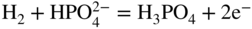

(19.6)
MCFC
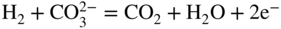
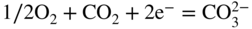
(19.7)
SOFC
H2 + O2− = H2O + 2e−
1/2O2 + 2e− = O2−
(19.8)
19.2 Molten Carbonate Fuel Cells
19.2.1 Introduction
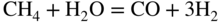
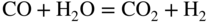
Company
Contact name
Email address
Fuel Cell Energy (USA)
Ramki Venkataraman
rvenkataraman@fce.com
POSCO Energy (South Korea)
Tae‐Won Lee
twlee@poscoenergy.com
Fuel Cell Energy Solutions (Germany)
Andreas Frömmel
afroemmel@fces.de
Franco Cell (France)
Marc Lemarignier
ml@francocell.eu
ENEA (Italy)
Stephen McPhail
stephen.mcphail@enea.it
University of Perugia (Italy)
Gabriele Discepoli
laboratorio.fuelcell@unipg.it
University of Genoa (Italy)
Barbara Bosio
barbara.bosio@unige.it
Fraunhofer‐IKTS (Germany)
Mykola Vinnichenko
Roland Weidl
mykola.vinnichenko@ikts.fraunhoffer.de
roland.weidl@ikts.fraunhofer.de
KTH (Sweden)
Carina Lagergren
carinal@kth.se
Chimie ParisTech (France)
Michel Cassir
michel.cassir@chimie‐paristech.fr
Warsaw Univ. Technology (Poland)
Jarek Milewski
milewski@itc.pw.edu.pl
University of Connecticut (USA)
Prabhakar Singh
singh@engr.uconn.edu
KIST (South Korea)
Jong‐Hee Han
jhan@kist.re.kr
19.2.2 The Operating Principles of an MCFC
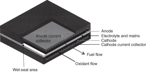


 ions to produce CO2 and H2O vapors, releasing electrons to the external circuit. Also, in the anode compartment, in the presence of metallic cell parts, at 650 °C, CO present in the fuel gas reacts with H2O vapor, yielding hydrogen, as shown in Eq. 19.3.


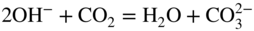
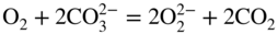


 is the peroxide ion and O2− is the oxide ion.
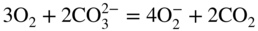
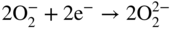
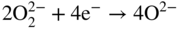
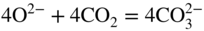

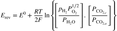
Reaction
ΔG0 (kJ mol−1)
E0 (V)
H2 + 1/2O2 = H2O
−196.92
1.020
CO + 1/2O2 = CO2
−202.51
1.049
CH4 + 2O2 = CO2 + 2H2O
−800.89
1.038
CH4 + H2O = CO + 3H2
−7.62
0.010
CH4 + CO2 = 2CO + 2H2
−2.04
0.003
CO + H2O = CO2 + H2
−5.58
0.029
2CO = C + CO2
−14.62
0.076
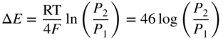
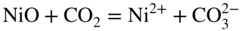
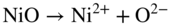


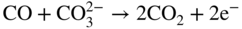

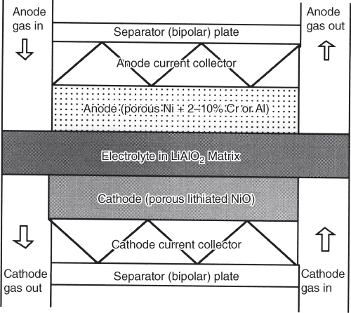
19.2.3 MCFC Anode Materials
19.2.4 MCFC Cathode Materials
19.2.5 MCFC Bipolar Current Collectors
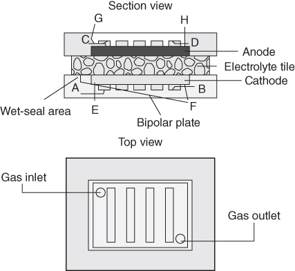
Fe‐based alloys
304, 304L, 310, 310S, 314, 316, 316L, 330, 347, 405, 430, 446, 17‐APH, 18SR, A118‐2, Al26‐1S, Al29‐4, Al439, Glass seal 27, Ferralium 255, RA 253 mA, Nitronic 50, 20Cb3, Crutemp‐25, Sanicro‐33, IN800, IN840, A‐286
Ni, Co‐based alloys
IN600, IN601, IN671, IN706, IN718, IN825, IN925, RA333, Ni200, Ni201, Ni270, Haynes 230, Haynes 625, Haynes 188, Haynes 556, Nichrome, Monel 400, Hastelloy C‐276
Al‐containing alloys
MA856, FeCrAl + Hf, Haynes 214, Fecralloy, IJR406, 85H, Kanthal AF, Kanthal A‐1, Ni3Al, FeAl
Items
Counter measures
1
Decay due to polarization
Optimization of pore structures
Control of fill ratio
Decrease in electrolyte loss
Pressed bipolar plate (smaller contact areas)
Li/Na‐type electrolyte
Lower solubility of the cathode
2
Decay due to ohmic loss
Soft seal‐type separator
Improved bipolar plate materials
Pressed bipolar plate
High‐quality Al coating
3
Decay due to ionic resistance
Optimization of electrolyte pore structures
Restriction of LiAlO2 phase transformations
Decrease in electrolyte loss
4
Decay due to Ni dissolution
Li/Na‐type electrolyte
Improved cathode (NiO + Mg, Fe)
19.2.6 MCFC Wet Seal
19.2.7 MCFC Electrolyte and Matrix
Endurance‐related properties
Rating
Characteristic value at 650 °C
Li/Na
Li/K
Unit
NiO cathode loss
⇑
1.3
4
μg h−1 cm−2
Corrosion (310 S)
⇔
29
50
μm yr−1/2
LiAlO2 stability
⇔
99+
99+
%
Electrolyte creepage
⇑
Vaporization loss
⇑
0.12
n.d.
μg h−1 cm−2
Performance‐related properties
Conductivity
⇑
2.4
1.65
1 (Ω cm)−1
Porous cathode impedance
⇑
−0.23
n.d.
Ω cm2
Surface tension/contact angle
⇓
77
n.d.
Degrees on Ni in fuel gas
Melting point
⇔
505
488
°C
O2 solubility
⇓
1.6
4.2
10−7 mol cm−3 atm−1
19.2.8 MCFC Hardware Materials
19.2.9 MCFC Future Directions
19.3 Solid Oxide Fuel Cells
19.3.1 Introduction
19.3.2 The Operating Principles of an SOFC
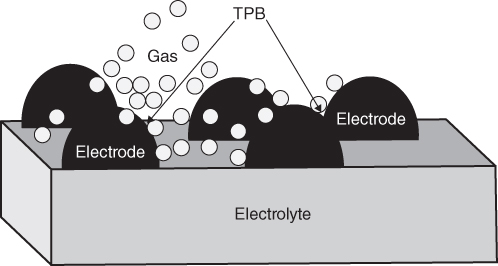
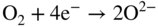


 is an oxygen ion in the YSZ electrolyte lattice site and
  is an oxygen vacancy in YSZ. It should be noted that the majority of H2 is generated by reforming hydrocarbons. The overall process is
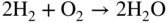
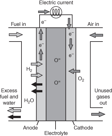
Alloy
Fe
Cr
Mn
Si
Al
La
C
Other
Crofer 22 APU
bal.
20–24
0.3–0.8
<0.5
<0.5
0.04
<0.03
<0.2 Ti
ZMG232L
bal.
21–23
1.0
<0.1
<0.5
0.03–0.1
<0.1
0.1–0.4 Zr
Sanergy HT
bal.
22
<0.5
<0.3
<0.05
1.0 Mo; 0.75 Nb
Crofer 22 H
bal.
20–24
0.8
0.1–0.6
<0.1
0.04–0.2
<0.03
0.2–1.0 Nb; 1.0–3.0 W; <0.2 Ti
19.3.3 Interconnect‐Related Corrosion Issues
19.3.3.1 Corrosion/oxidation
 to oxidize Cr to Cr2O3 at 800 °C is only 10−20 atm; thus most FSS are observed to form an outer Cr2O3 scale also in the anodic atmosphere (Liu 2008). The reports on whether the oxidation rates in anodic atmospheres are lower (Palcut et al. 2010), higher (Linder et al. 2013), or the same (Alnegren et al. 2016) as in air are conflicting. Niewolak et al. (2014) suggested that the disagreement in literature could be related to different Mn contents in the steels. They reported a lower long‐term oxidation rate in simulated anode atmosphere than in air when the Mn content was sufficient to form a continuous Cr–Mn spinel layer on the surface. The potentially greatest threat for the stability of metallic interconnects on the anode side is the observed diffusion of Ni from the anode into the FSS, leading to austenite formation.
19.3.3.2 Chromium Evaporation
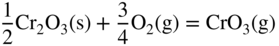
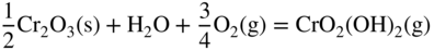
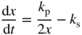

19.3.3.3 Electrical Conduction of Oxide Scales

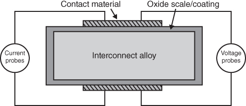
19.3.4 Protective Coatings for Metallic Interconnects
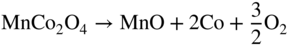
Mg
Mn
Co
Ni
Cu
Zn
MgAl2O4
MnAl2O4
CoAl2O4
NiAl2O4
CuAl2O4
ZnAl2O4
Al
σ = 10−6
σ = 10−3
σ = 10−5
σ = 10−4
σ = 0.05
σ = 10−6
α = 9.0
α = 7.9
α = 8.7
α = 8.1
α = −
α = 8.7
MgCr2O4
Mn1.2Cr1.8O4
CoCr2O4
NiCr2O4
CuCr2O4
ZnCr2O4
Cr
σ = 0.02
σ = 0.02
σ = 7.4
σ = 0.73
σ = 0.40
σ = 0.01
α = 7.2
α = 6.8
α = 7.5
α = 7.3
α = −
α = 7.1
MgMn2O4
Mn3O4
CoMn2O4
NiMn2O4
Cu1.3Mn1.7O4
ZnMn2O4
Mn
σ = 0.97
σ = 0.10
σ = 6.4
σ = 1.4
σ = 225 (750 °C)
α = 8.7
α = 8.8
α = 7.0
α = 8.5
α = 12.2
MgFe2O4
MnFe2O4
CoFe2O4
NiFe2O4
CuFe2O4
ZnFe2O4
Fe
σ = 0.08
σ = 8.0
σ = 0.93
σ = 0.26
σ = 9.1
σ = 0.07
α = 12.3
α = 12.5
α = 12.1
α = 10.8
α = 11.2
α = 7.0
MnCo2O4
Co3O4
Co
σ = 60
σ = 6.7
α = 9.7
α = 9.3
19.4 Direct Carbon Fuel Cells
19.4.1 Basic Overview
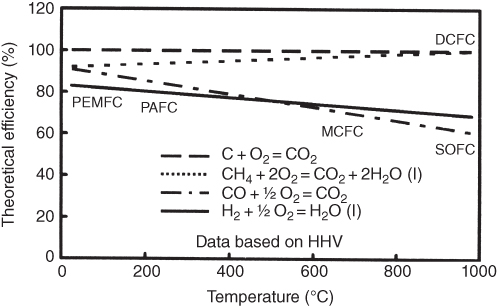

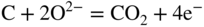
Fuel/anode
Electrolyte
Cathode
T (°C)
Solid graphite rod as fuel and anode
C + 4OH− = 2H2O + CO2 + 4e−
Molten hydroxides
OH− ←
Air as oxidant
O2 + 2H2O + 4e− = 4OH−
∼600
Carbon particles as fuel in molten carbonate and anode 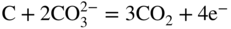
Molten carbonates 
Air as oxidant 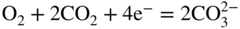
∼800
Carbon particles in a fluidized bed
C + 2O2− = CO2 + 4e−
Oxygen ion conducting ceramic electrolyte
O2− ←
Air as oxidant
O2 + 4e− = 2O2−
800–950
Fuel in contact with molten tin
Sn + 2O2− = SnO2 + 4e−
Carbon particles as fuel in molten carbonate and anode
C + 2O2− = CO2 + 4e−
19.4.2 DCFC with Molten Carbonate as Electrolyte
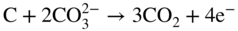
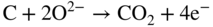
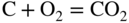
 ions migrating from the cathode toward the anode. At MCFC operating temperatures, carbon can be oxidized to CO2 via the cathode and anode reactions shown above (Eqs. (19.8), 19.47, and 19.48).
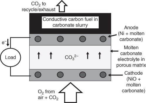
19.4.3 DCFC with Oxygen Ion Conductor as Electrolyte
19.4.3.1 Gasification‐Driven Direct Carbon SOFCs
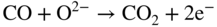

19.4.3.2 Direct Carbon SOFCs with Molten Carbonate Anodes
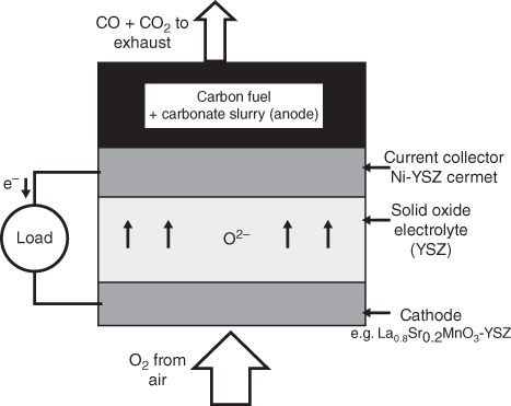
19.4.3.3 Direct Carbon SOFCs with Molten Metal Anodes
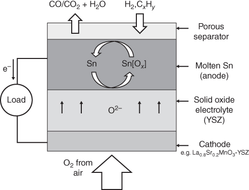
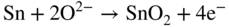

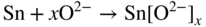

19.4.4 DCFC with Molten Salt as Electrolyte


DCFC technology
Status
Molten hydroxide
Average power densities of 40 mW cm−2 for over 540 h of operation with peak power density of 180 mW cm−2. The maximum efficiency achieved is 60%
Molten carbonate
Power densities to 100–120 mW cm−2 and 80% efficiency with fuels such as fossil chars, petroleum coke, carbon blacks
Solid oxide
Solid carbon fuel
The peak power density achieved is reported to be 140 mW cm−2 at 900 °C with synthetic carbon agitated with CO2
Solid oxide
Carbon mixed with molten metal
The peak power density achieved so far is about 160 mW cm−2, respectively, from hydrogen and liquid fuel JP‐8. The company has built and tested cells, small stacks, and systems for short periods of time
Solid oxide
Carbon mixed with molten carbonate
The peak power density achieved is 120 mW cm−2 using acetylene black as the fuel. SRI International has tested a 6 W six‐cell (six cathode/electrolyte tubes in a single salt bath) demonstration stack using different fuels
19.4.5 Conclusions
19.5 Nuclear Power Plants
19.5.1 Nuclear Renaissance
19.5.2 Nuclear Reactor Types
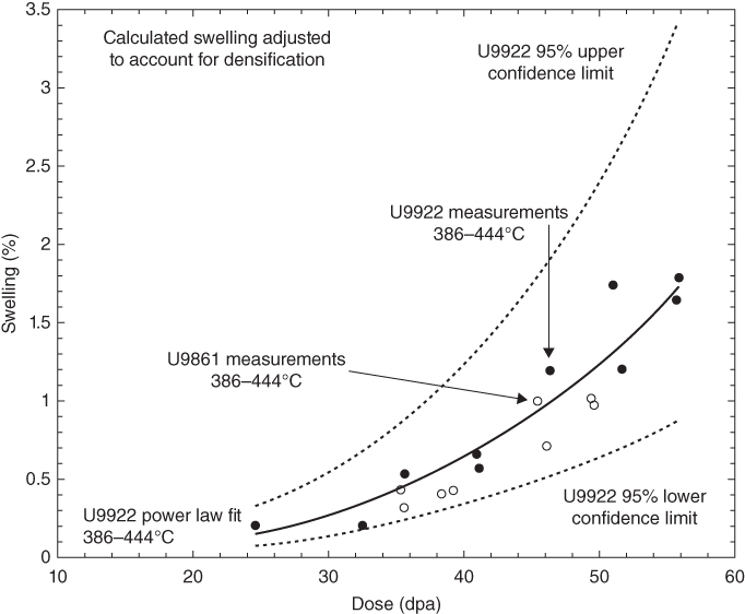
19.5.3 Materials for Nuclear Reactors
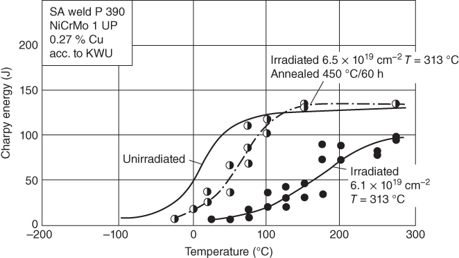
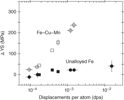
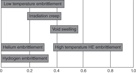
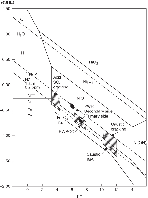
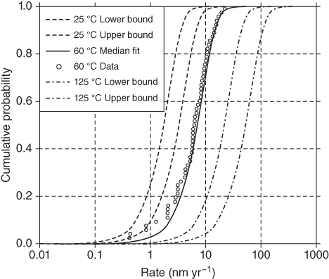
Designation
ASTM Standard B350‐80: zirconium–tin Alloy, UNS R60802
Trade names
Zircaloy 2; Sandvik Zircaloy 2, Sandvik Steel Co. (USA); Zircaloy‐2, Sandvik/Coromant (USA); Zircaloy 2, Westinghouse Electric Corp. (USA)
Composition (summary)
Zr/1.2–1.7Sn/0.07–0.2Fe/0.05–0.15Cr/0.03–0.08Ni/+ various lesser impurities
Composition details
Base
Zr (zirconium)
Cr (chromium)
0.05
—
0.15%
Fe (iron)
0.07
—
0.2%
Ni (nickel)
0.03
—
0.08%
Sn (tin)
1.2
—
1.7%
Zr (zirconium)
97.9
—
98.7%
Density
6450
—
6650 kg m−3
Price
*24.7
—
27.2 USD kg
Mechanical properties
Young’s modulus
*90
—
105 GPa
Shear modulus
*30
—
40 GPa
Bulk modulus
*100
—
150 GPa
Poisson’s ratio
*0.35
—
0.38
Yield strength (elastic limit)
240
—
490 MPa
Tensile strength
410
—
520 MPa
Compressive strength
*240
—
490 MPa
Flexure strength (modulus of rupture)
*240
—
490 MPa
Elongation
14
—
32%
Hardness – Vickers
200
—
240 HV
Fatigue strength at 107 cycles
*160
—
260 MPa
Fracture toughness
*115
—
150 MPa m−1/2
Mechanical loss coefficient (tan δ)
*3e−4
—
9e−4
Thermal properties
Melting point
2100
—
2130 K
Maximum service temperature
*643
—
783 K
Thermal conductivity
11
—
14 W m K−1
Specific heat capacity
274
—
286 j kg K−1
Thermal expansion coefficient
5.5
—
5.9 μstrain/°C
Typical uses
Fuel rod cladding in boiling water reactors (BWRs)
Warning
May become radioactively contaminated during use. Small pieces of zirconium, e.g. machine chips and turnings, can be a fire hazard. Nonradioactive zirconium is toxic, but only if ingested in large quantities
Other notes
The mechanical properties of Zr alloys vary strongly with oxygen impurity levels. Zirconium ore naturally contains a few per cent hafnium, which has very similar properties to Zr. For nuclear applications, this has to be removed, as Hf absorbs neutrons
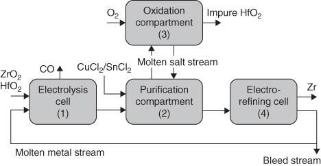
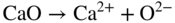


19.5.4 Corrosion in Nuclear Applications


References
Further Reading
Examples of Engineering Importance
19.1
19.2
19.3
19.9
19.10
19.11
19.12
19.13
19.14
19.15
19.16
19.17
19.18
19.19
19.20
19.21
19.22
19.23
19.24
19.25
19.26
19.27
19.28
19.29
19.30
19.31
19.32
19.33
19.34
19.35
19.36
19.37
19.38
19.39
19.40
19.41
19.42
19.43
19.44
19.45
19.46
19.47
19.48
19.49
19.50
19.51
19.52
19.53
19.54
19.55
19.56
19.57
19.58
19.59
19.60
19.61
19.62
19.63
19.64
19.65
19.66
19.67
19.68
19.69
19.70
19.71
19.72
19.73
19.74
19.75