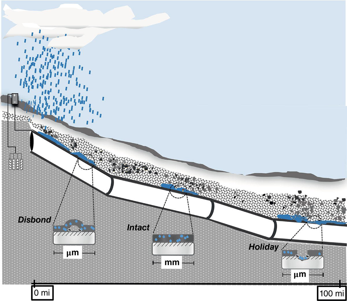
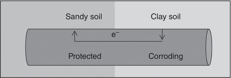
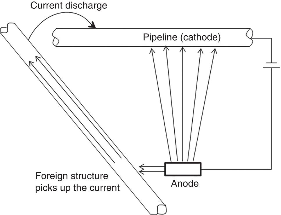
Homero Castaneda1 Hui Wang2 and Omar Rosas3 1Materials Science and Engineering Department, National Corrosion and Materials Reliability Laboratory, Texas A&M University, College Station, TX, USA 2Department of Civil and Environmental Engineering, University of Dayton, Dayton, OH, USA 3Deepwater Corrosion Services, Inc., Houston, TX, USA The characteristics of the electrochemical cell formed at an underground pipeline are discussed in this chapter. Considering the pipeline as the electrode and the soil as the electrolyte, the properties that control corrosion activity can be characterized. Technologies for detecting and monitoring the state of external corrosion of oil and gas pipelines will be described by considering the underground pipeline as electrochemical, or electrical, in nature. Modeling of external corrosion has become an important tool to implement the current preventative technologies and is used to support analyses of the information acquired from each survey or inspection method. Critical factors incorporated into modeling help to characterize not only the position of external corrosion but also the time-dependent effect of the dissolution mechanism. The factors range from macro- to microscale in nature. This chapter includes the description, quantification, and influence of critical factors for external corrosion of buried pipelines. The classification of the factors is based on the multiscale approach for onshore pipelines. Furthermore, the field and laboratory techniques used to detect, characterize, and monitor the state of the pipeline will be categorized based on the micro and macro parameters. Pipelines are exposed to various environmental elements that can interact with them and cause integrity damage. The soil, oxygen in the air, rainfall, temperature, moisture, vegetation, and electrolytes suspended in the atmosphere can interact with the pipeline and cause it to corrode. Corrosion is a time-dependent threat in pipelines exposed to underground conditions and is one of the prime causes of pipeline failure. Soil, as defined by Rim-Rukeh et al. [1], is a complex material consisting of a discontinuous and heterogeneous environment that is constituted by an organic solid phase, liquid water phase, air, and other gas phases. It is estimated that a pipeline failure occurs on an average of every 2–4 months in the United States, with the most common failure mechanism being localized corrosion [2, 3]. In soils, water and gas occupy the spaces between solid particles, and these spaces can constitute as much as half the volume of dry soil. Some of the water in the soil is bound to mineral surfaces, whereas bulk water can flow through porous soil. Fluid flow through soil is controlled by the permeability of the soil, which, in turn, depends on the size distribution of the solid particles in the soil. For example, good drainage can occur in coarse-grained sand, and atmospheric oxygen can penetrate to a depth greater than that which would be reached, for example, in fine-grained soil high in clay. Capillary action in fine-grained soil can draw water up, keeping the soil saturated with water, preventing drainage, retarding evaporation, and restricting oxygen access from the atmosphere to the pipeline. The electrochemical corrosion processes taking place on metal surfaces in soils occur in groundwater that is in contact with the metallic structures. Damage evolution of the pipe coating, of the coating/steel interface, and of the steel beneath the coating is based on initiation conditions and time-dependent parameters that produce and influence various processes. Both the soil and the climate influence the groundwater composition and the factors that control the damage/failure process. The damage evolution process can be defined in four stages by assuming the pipeline/coating intact conditions, as illustrated in Figure 49.1. Stage I is the initiation, which comprises the transport of species toward and within the pipe coating under cathodic protection conditions. Stage II includes the activation of the steel substrate and corrosion product formation, during which any change in volume or physical modification of the pipe coating is thermodynamically feasible. Any anomaly built due to the stresses induced by the corrosion products or third-party damage resulting in a holiday, which is a defect in the pipe coating, is an indication for Stage III, where the environment is in direct contact with the steel substrate. Stage IV, the final stage, is the metal loss leading to a leak or rupture of the pipe. The parameters of each stage that are critical to the performance of the corrosion control and protection system are explored in this chapter. Figure 49.1 Damage evolution stages for buried pipeline/coating systems. Pipelines are expected to function reliably and continuously over several decades without failure or extended damage from corrosion. Various parameters in the soil can affect pipeline damage, for example, pH, moisture content, resistivity, ion content, redox potential, physical, and chemical characteristics of the type of soil, oxygen content, and microbes present in the soil [4]. Different components that form the electrochemical cell affect the damage evolution and will indirectly or directly influence each of the damage evolution stages. The electrochemical and transport processes at the metal/coating interface are influenced by the water (or electrolyte) uptake on the metal surface as well as the chemistry of the film, in addition to the oxide layer formation on the surface and the interactions with the soil. The external interactions with the soil are environmental, electrical, and mechanical in nature and include weather, climate, stray currents, and telluric effects among others. The microenvironments due to oxygen, moisture, and other species migrating through the soil to the metal surface control these macro metal/moisture environments and influence corrosion. The macroenvironment will further influence the soil condition and corrosivity [5]. A multiscale concept becomes important for the critical factors for external corrosion in buried onshore pipelines. Figure 49.2 illustrates the multiscale concept for the degradation mechanisms. Along the right-of-way (ROW) on a pipeline/soil system, different ecosystems will influence the local and general conditions of the pipeline. We can identify and characterize different damage evolution stages from the submillimeter to meter scales. Based on a multiscale concept, various factors affect the aggressivity of the soil, which, in turn, influences the integrity and reliability of a pipeline. Most often, the corrosivity of the soil determines the mode of protection offered to a pipeline, the survey technology used, and the current estimate of reliability. Several important variables have been identified that have an influence on corrosion rates and damage evolution in soils. These include the type of soil, amount of water, degree of aeration, pH, redox potential, resistivity, soluble ionic species (salts and organics), and microbiological activity. This complexity is pictured in Figure 49.3. Some variables affecting pipeline corrosivity are discussed below. Ecosystems influence the soil properties distribution from the original state. Differences are proportional to the local properties of the electrolyte, and the accumulation of several local conditions drives the characteristics of a large area. Multiscale characteristics can be divided into macro and micro parameters. The macro, or global, parameters cover larger areas of incidence in the ROW, such as precipitation, temperature, topography, vegetation, evapotranspiration, CO2, and humidity. The moisture conditions can be the link between macro and micro conditions, and the natural soil distribution is affected by the presence of water. The water balance depends on several factors: transport within the soil; the water input due to environmental conditions; the output influenced by drainage, soil properties, and distribution; and the accumulation of water due to the soil properties. Among the critical parameters for local micro conditions, the soil plays an important role; the soil directly interacts with the atmospheric and above-ground conditions while also covering the surface of the metallic pipeline. The soil properties can control both local and global conditions. For example, the particle size influences the moisture saturation and water content. Different parameters to consider for local conditions include the soil skeleton, pore structure, and level of compaction due to the density or porosity. The distribution of the soil properties cannot be measured under field conditions. One parameter that can be critical to soil characterization is resistivity. Historically, resistivity has often been used as an indicator of soil corrosivity. Because ionic current flow is associated with transport mechanisms leading to corrosion, high soil resistivity will arguably slow down the transport kinetics for each stage in the damage evolution process. Liu et al. [7] found that soil resistivity was the most important factor contributing to pipeline damage. The resistivity value of the soil decreases with the increase of the moisture content in the soil [8]. Obtaining a good correlation between resistivity observed in the field and in the laboratory has yet to be achieved [9]. Soil resistivity generally decreases with increasing water content and the concentration of ionic species. Soil resistivity is by no means the only parameter affecting the risk of corrosion damage; a high soil resistivity alone will not guarantee the absence of metallic and coating damage. Figure 49.2 Multiscale concept for corrosion assessment of a buried pipeline. ([6]/Elsevier.) Figure 49.3 Variables affecting corrosion in soil. MIC effects are presented only for sulfate-reducing bacteria. (Adapted from [7].) Figure 49.4 Wenner four-pin technique for measuring soil resistivity. (Adapted from [10].) Table 49.1 Soil Types/Resistivity and their Effect on the External Corrosion Rate of Bare Carbon Steel with No Cathodic Protection [11, 12] Variations in soil resistivity along the length of a pipeline are highly undesirable because they will lead to the formation of macrocorrosion cells. For pipelines, the merit of a corrosion risk classification based on an absolute value of soil resistivity is not robust. Soil resistivity can be measured by the so-called Wenner four-pin technique as illustrated in Figure 49.4, or more recently, by 3D electromagnetic survey technologies. The latter allows measurements in a convenient manner and at different soil depths. Another option for soil resistivity measurements is the so-called soil box method, whereby a sample is taken during excavation. Preferably, the sampling will be performed in the immediate vicinity of the pipeline (in a pipe trench, for example). Table 49.1 shows the effect of soil type and moisture content on the corrosive behavior of the soil. Water in liquid form represents the essential electrolyte required for electrochemical corrosion reactions. In soils, a distinction is made between saturated and unsaturated water flow/accumulation. Unsaturated water flow refers to the movement of water from wet areas toward dry soil areas. Saturated water flow is dependent on pore size and distribution, texture, structure, and organic matter. High-moisture content facilitates faster transport of ions between the pipeline surface and the soil, causing the soil to be more corrosive. Water movement in soil can occur by the following mechanisms: gravity, capillary action, osmotic pressure (from dissolved species), and electrostatic interaction with soil particles. The water-holding capacity of soil is strongly dependent on its texture; coarse sands retain very little water, while fine clay soils store water to a high degree. Gupta et al. [13] observed that the maximum corrosivity of steel occurs when the moisture content is 65% of its water-holding capacity and termed this as the “critical moisture-holding content.” Moreover, moisture content is not the only factor that is found to control the corrosion of ferrous metals. Neale et al. [14] observed that depending on the soil type, the saturation of water in the soil vary from as low as 0.5% for sand to as high as 217% for bentonite clay. In addition, it has also been reported that low moisture content favors localized corrosion [5]. Castaneda et al. [15] created drainage maps for water accumulation at different depths. The spatial distribution of precipitation, evapotranspiration, and drainage was used to map water accumulation, as illustrated in Figure 49.5. Figure 49.5 Varying quantities of water covering the entire pipe: (a) no coverage, (b) partial coverage, and (c) total coverage. Alkaline soil conditions can be corrosive or lead to threats to steels under certain conditions. This is corroborated by thermodynamic data for Fe–H2O equilibrium. Moreover, pipelines at high pH (more than 11, depending on the iron concentration, temperature, and ionic species in solution) can produce alkali and hydrogen formation producing local conditions for active corrosion, coating-delamination, or hydrogen embrittlement [16]. Acidic environments, however, are detrimental to steel pipelines. The acid acts as a depolarizing agent and causes difficulty in the polarization of the pipeline along the protective potential. Thus, a higher current density is required to maintain cathodic protection in the acidic area. Table 49.2 shows the effect of pH on the corrosion of buried steel pipelines [17]. Stress corrosion cracking (SCC) is a corrosion mode influenced by the soil pH. Near neutral and alkaline SCC includes two different forms of attack that are produced by different mechanisms, which can affect metallic pipelines. The former produces transgranular attack due to the required energy taken for the mechanism; the latter includes intergranular attack. Table 49.2 Effect of pH on Corrosion of Buried Steel Pipelinesa Source: Data from [17]. a Note: Factors other than pH (e.g., resistivity and moisture) can also be important and must be considered. The chlorides and sulfates present in the soil can also influence the corrosivity of the soil and damage the evolution of the pipeline/soil system. Their contribution to the corrosion process is significant, and at high concentrations, they may cause severe corrosion in steel pipelines. Chlorides promote corrosion due to their conductive nature. In addition, they inhibit passive oxide film formation and thus promote localized corrosion. Moreover, the presence of chloride tends to decrease soil resistivity [1]. Chloride ions can originate from brackish groundwater, mine drilling shafts, and human activities, such as the de-icing of roads. The concentration of chlorides can also vary with the season. Data have shown that there is a systematic decrease in soil resistivity with an increase in both chlorides and sulfates [18]. Table 49.3 shows the effects of chlorides and sulfates on the corrosion of buried steel pipelines. Table 49.3 Effects of Chlorides and Sulfates on the Corrosion of Buried Steel Pipelines [9] Source: Data from [9]. Differential cell corrosion is the most common mechanism that causes localized corrosion of pipelines. The soil corrosivity in underground pipelines can be influenced by the level of oxygen concentration at different regions of the pipeline, creating differential cell aeration, as well as by any differences in soil chemistry or pipeline surface [6]. The region of higher oxygen concentration acts as a cathode, whereas the oxygen-deficient region acts as an anode. Differential cell corrosion can be autocatalytic in nature. The chemical and electrochemical reactions and ion migration tend to generate conditions favorable to the continuation of the cell [6]. Figure 49.6 depicts a pipeline passing through two different types of soil. The potential of the pipeline in the clay soil is more anodic compared to the potential of the pipeline in the dry sandy soil, and hence, a corrosion cell is generated. The pipeline in the clay soil is corroded, whereas the pipeline in the sandy soil is protected. Differential corrosion cells can also be generated by differences in moisture content in soil or differences in oxygen diffusion through the soil. Figure 49.6 A differential corrosion cell generated due to differences in the soil type. ([6]/with permission of Elsevier.) The presence of bacteria and fungi in the periphery of the pipeline can change the corrosion behavior of the pipeline. This is also known as microbially induced corrosion (MIC) [19–22]. It is estimated to contribute to 20–30% of the external corrosion of pipelines [23]. Certain bacteria can exist in the absence of oxygen (anaerobically) at the surface of the pipeline and reduce any sulfates present therein while consuming hydrogen during the process. A hydrogen deficiency will depolarize the steel at the cathodic areas, resulting in more rapid consumption of metal/pipeline. Thus, the corrosion of steel pipelines is accelerated in the presence of sulfate-reducing bacteria (SRB) because the bacteria create an environment that supports a more rapid attack. The bacterial activity causes the OCP (open circuit potential) of the anodic areas to be more negative. The attack is aggressive in the presence of bacterial communities, with acid-producing bacteria causing the most aggressive corrosion of underground pipelines [23]. A higher than normal potential is used during cathodic protection of such pipelines. An additional −0.1 V in addition to the conventional −0.85 V (CSE/copper sulfate electrode) is suggested under this condition [11, 24, 25]. The redox potential measures the degree of soil aeration. It is an also an indicator of whether a soil can sustain SRB. A high-redox potential value indicates a higher oxygen content and vice versa. SRB proliferates at low redox potentials [26, 27]. It has also been observed that redox potential and resistivity are better indicators of soil corrosiveness than moisture content [17]. Ideally, any highly corrosive environments along a proposed pipeline route would be identified before pipeline installation. Various ASTM standard methods can be used to test for soil resistivity and pH. ASTM G57 is one such test for Field Measurement of Soil Resistivity. Other ASTM test methods include ASTM G51-95(2102) for measuring the pH of Soil, ASTM G200-09 for the Measurement of Oxidation–Reduction Potential (ORP) of soil, and ASTM G162-99(2010) for Conducting and Evaluating Laboratory Corrosion Tests in Soils [28–31]. After identifying the risk or likelihood of corrosion of a buried pipeline in a certain environment by evaluating the factors involved in this process, different methodologies have to be followed to either prevent or counterattack the effect of corrosion. The main methods for corrosion mitigation on underground pipelines are coatings and cathodic protection (CP) (discussed in Chapters 24 and 26, respectively). On a cathodically protected pipe, the coating reduces the surface area of exposed steel on the pipeline, thereby reducing the current necessary to cathodically protect the steel. Cathodic protection is used to reduce the corrosion rate of a metal surface by making it the cathode of an electrochemical cell. The principle for cathodic protection is illustrated in Figure 49.7 [32]. The electrons are supplied to the pipeline by using a dc source and an anode. In the case of a coated pipeline, current flows to the areas where the coating is defective. An electron current flows along the electric cables connecting the anode to the cathode, and an ionic current flows in the soil between the anode and cathode to complete the circuit. The primary goal of cathodic protection is to lower the potential of the buried structure. As long as the cathodic current is increased, the potential of the metal decreases; for each increment that the potential of the metal is reduced, the current requirements tend to increase exponentially. Figure 49.7 Current distribution during the cathodic protection of a pipeline. (Adapted from [7].) A poor CP design may be a cause of damage to the pipeline; some of the key indicators are bad current distribution, interferences, or stray currents. Stray currents are currents flowing in the electrolyte (soil) from external sources not associated with the CP system. Corrosion damage to an underground structure caused by a CP system on another structure is a form of stray current corrosion that is commonly called “interference.” Stray current damage is most commonly associated with impressed current CP systems. A foreign pipeline or other metallic structure can form a second resistance path where the current distribution can be deviated from the coverage areas that the pipeline requires to complete the protection system. Figure 49.8 illustrates a foreign pipeline passing through a zone of positive soil potentials (area of influence) and protected by an impressed current system. In this illustration, a pipeline crosses the one selected for protection at a more remote location. The positive soil potentials will force the foreign pipeline to pick up current at points within the area of influence. This current must then complete the electrical circuit and return to the negative terminal of the DC power source. The figure illustrates this by showing the current path distribution flowing along the foreign line (nonoriginal protected) toward the point where the two lines cross and then leaving the foreign line in the vicinity of the crossing. This current then flows into the protected pipeline and returns to the rectifier. The area where the current leaves the foreign line in the vicinity of the crossing becomes a potential site for corrosion in the foreign pipeline. Usually, a small amount of current will flow along the foreign pipeline in the opposite direction from the ground bed area. This is indicated as a final current path in the figure. This current will leave the foreign pipeline at remote locations, usually in areas of relatively low soil resistivity. The severity of the effect is largely a function of the impressed voltage on the ground bed and the proximity of the foreign pipeline to the ground bed. Where the impressed voltage is high, and the foreign pipeline is close to it, the current forced onto the foreign pipeline tends to be high and can cause damage. In such instances, the foreign pipeline represents a potential threat leading to weak integrity. Figure 49.8 Anodic and cathodic interference example. (Adapted from [7].) Once the source is identified, the current path can be distributed to correct the problem. A better electrical balance can produce suitable current distribution and avoid the high current drainage at the potential corrosion location; connecting a resistance between the two metallic conductors (protected and foreign pipelines), the magnitude of the electrical passive element (resistance) shall be calculated in order to distribute the current drain from a specific location to higher areas. Cathodic protection design (or redesign) can be also considered as a preventive or control action. Relocation of the anodic bed, the addition of passive elements (such as resistors), and more efficient current pathways in the electrical configuration are some examples of remediation actions [11]. Corrosion in pipelines is a time-dependent threat that can be monitored under field conditions and characterized or quantified under laboratory conditions by simulating field metal/coating/soil systems. Inspection under field conditions presents some challenges due to the area extension for pipeline/soil in the right-of-way. Direct and indirect measurements can be used to monitor and inspect the state of either component of the pipeline/coating system, such as the coating, cathodic protection coating failure, and metallic activation. Table 49.4 illustrates the technologies used in the field for direct measurements on pipelines; for example, metal loss and coating failure can be detected using different technologies for in-line inspection (ILI), such as magnetic flux leakage (MFL) and ultrasound (UT). Table 49.4 Tools for Inspection of Buried Structures in Soils Source: [6]/Elsevier/CC-BY 4.0. Difficult right-of-way can add challenges for successfully using the inspection tools. The lack of facilities to deploy ILI devices considers the indirect measurements as viable or the only choice to monitor the state of the buried pipeline. There are some well-established indirect technologies for external inspection of buried structures that are used to identify and resolve stable as well as time-dependent threats, such as coating anomalies, corrosion, and the effectiveness of cathodic protection. The technologies illustrated in Table 49.4 include DCVG (direct current voltage gradient), ACVG (alternate current voltage gradient), CIS (close interval survey), and PCM (pipeline current mapping) for characterizing and quantifying the local corrosion conditions. The previous sections have shown that a variety of parameters control the properties of soil and the electrolyte of the corrosion cell that develops. Sampling or measurement on-site on a small scale can be used to characterize the state of the buried metallic structure and of the environment. By measuring the mass loss of coupons in the field, the corrosion rate can be quantified (See Chapter 28). The open circuit potential is the electrode potential with respect to a reference electrode similar to the CIS indirect measurement. The OCP represents the active–passive corrosion condition at the specific area where the OCP is measured. Additional laboratory testing may include linear polarization resistance (LPR) for measuring the corrosion rate and electrochemical impedance spectroscopy (EIS) for characterizing the corrosion of pipeline samples in laboratory-simulated conditions. Soil corrosivity is evaluated by characterizing the soil, the pH, and the ionic speciation.
49
External Corrosion of Pipelines in Soil
49.1 Introduction
49.2 Background

49.3 Critical Factors of Soil Corrosivity that Affect Pipelines
49.3.1 Multiscale Factors Influencing External Corrosion Related to Soil Properties and Conditions


Soil Type
Soil Resistivity (ohm-cm)
Moisture
Corrosion Rate (mm/year)
Muskeg/sloughs/free water accumulations
<500
Always wet
Very corrosive (>1.0)
Loams/clays
500–2000
Mainly wet
Corrosive to moderately corrosive (0.5–1.0)
Gravels, sandy
2000–10000
Mainly dry
Mildly corrosive (0.2–0.5)
Arid, sandy
>10000
Always dry
Noncorrosive (<0.2)
49.3.2 Water Coverage due to Vapor Transportation and Drainage

49.3.3 pH of Soils
pH
Relative Corrosivity
<5.5
Severe
5.5–6.5
Moderate
6.5–7.5
Neutral
>7.5
None (alkaline)
49.3.4 Chlorides and Sulfates in Soils
Concentration (ppm)
Relative Corrosivity
Chloride
>5000
Severe
1500–5000
Considerable
500–1500
Moderate
<500
Threshold
Sulfates
>10,000
Severe
1500–10,000
Considerable
150–1500
Moderate
1–150
Negligible
49.3.5 Differential Aeration Corrosion Cells
49.3.6 Microorganisms in Soils1
49.3.7 Redox Potential
49.4 Identifying Corrosive Environments
49.5 Cathodic Protection and Stray Currents

49.6 Monitoring and Inspection for Corrosion Characterization Under Multiscale Conditions
Technology Technique
Field
Laboratory
Direct/Indirect
Macro >1 ft
Transition 1 ft
Micro <1 ft
Macro >1 ft
Transition 1 ft
Micro <1 ft
ILI
a) MFL
Direct (metal loss)
b) MFL axial
Direct (metal loss)
c) MFL circumf.
Direct (metal loss)
d) UT
Direct (metal loss)
CIS
Indirect (potential)
DCVG
Indirect (voltage)
ACVG
Indirect (bias)
PCM
Indirect (current)
Pipe to soil potential
Indirect (potential)
OCP
Indirect (potential)
LPR
Direct (metal loss)
EIS
Direct (metal loss)
Weight loss
Direct (metal loss)
Resistivity
Indirect (resistance)
pH
Direct/Indirect (pH)
Ionic
Indirect (Cl−,SO42−,HCO3−)
References
Note