section epub:type=”chapter” role=”doc-chapter”> The problem of high temperature fireside corrosion in coal‐ and oil‐fired steam generating plants, and generally in heat‐recovery units, has been well recognized over the past decades. Its practical importance is easily understood considering that damages are not always limited to the replacement of corroded tubes and to the consequent interruption of steam production. Indeed, the blowdown may cause well heavier losses as, for instance, the breaking off of steel production should the damage occur in a heat‐recovery unit of a steel plant. Since the end of World War II, when the first cases of fireside corrosion were experienced, a great deal of research has been conducted in order to elucidate corrosion mechanisms and to assess methods of preventing it. Soon it became apparent that corrosion was primarily due to the condensation from the flue gases, on the comparatively cool metal tubing surfaces, of highly aggressive deposits that, at the operating tube temperature, were soft or liquid. Whether such deposits come entirely from the flue gases or are formed through a reaction between flue gas component and tube metal has been a matter of speculation, and some issues have not yet been fully resolved. Nevertheless, the important point is that whatever the origin of deposits, their aggressiveness largely depends on their physical state, i.e. the molten or semi‐molten state. Deposits from fireside areas that have suffered external corrosion almost invariably contain appreciable quantities of alkali sulfates. The amount of such constituents largely depends on the nature of the burning fuel; it ranges from 35% to 50% sulfur reported as SO3 in coal‐fired furnaces to 25–45% in oil‐fired units. In every case, such deposits are water soluble, with a pH as low as 3, the acidity being due to the excess of SO3 in alkali sulfates released by hydrolysis. The nature of these complex deposits has been investigated since their existence was recognized more than 70 years ago. These sulfates are reported as complex trisulfates whose chemical stability depends primarily on temperature and SO3 content of the atmosphere. Actually, their formation could be explained by the following reaction: Of the three reagents, at least two come from the flue gas and therefore from the fuel, the third, iron oxide, from the tube oxide scale. On the other hand, the formation of aluminum trisulfates, for example, may be entirely caused by reagents coming from the environments: that is the case of coal‐fired furnaces where larger bulks of aluminosilicate materials come from combustion residues. Obviously enough, the early investigations attempted to reproduce in the laboratory the corrosion phenomena encountered in the field. These investigations helped to understand the fundamental role of SO3 in the progression of Reaction 16.1 as well as the importance of temperature level in deciding the stability of complex trisulfates. Their occurrence and hence their aggressiveness is restricted to a relatively narrow temperature range. Furthermore it was recognized that the SO3 concentrations usually encountered in flue gases (25–35 ppm) were insufficient to progress Reaction 16.1 in laboratory experiments where a SO3 concentration as high as 250 ppm was found necessary. Actually, the slow attainment of equilibrium of reaction causes SO3 to be only about 1% of the SO2 in the flue gas. Thus, a good deal of research has been conducted to establish the catalytic effect of iron oxide surfaces to speed up the formation of SO3 in Reaction 16.2 in order to explain the practical occurrence of complex trisulfates. It has been a matter of controversy the mechanism through which the tube wastage by molten complex sulfates takes place. Some authors maintain that the metal loss is essentially due to the scale‐destroying Reaction 16.1 in which complex sulfates are formed. Its progression depends on periodic tube deslagging and subsequent thermal decomposition of trisulfates to provide the necessary SO3. Others believe that losses are due to a direct redox reaction of complex sulfates on the tube metal through a scale‐creating irreversible pattern: Reactions 16.1 and 16.3 are somewhat different, the latter taking place at higher temperatures and its progression generating in addition to iron oxide also iron sulfate as corrosion product. Furthermore, the complex sulfates are generated in the ash deposits, and the contact between the tube metal and the corrodent is provided by migration of molten deposits under a thermal gradient. Previous discussion has been confined to molten sulfates as cause of metal wastage in boilers. Actually in oil‐fired units, deposits contain appreciable amounts of vanadium compounds. Vanadium comes from the oil, and vanadate formation takes place through an acid–base reaction in the flue gas with alkali metal species also coming from the fuel; vanadates subsequently condense on superheater tubes as liquid aggressive layers. Other components that could be responsible for corrosion by flue gas deposits are chlorides. These can be found in both coal‐ and oil‐fired boilers; the conditions of their occurrence, as well as their general behavior, are well described by Lai (2007). The conclusions are that excepting the case of nonequilibrium conditions in which anomalous situations may arise, chlorides entering the system with fuel will remain mostly in the gas phase without participating in the corrosion process. Therefore, as written previously, high temperature fireside corrosion in coal or oil burning boilers is best outlined by admitting the presence of molten or semi‐molten deposits. Obviously, corrosion is affected by transport processes across deposits and by reactions occurring at gas–deposit interfaces and deposit‐metal surfaces. The presence of a molten phase is a sufficient prerequisite to stimulate both transport processes and heterogeneous reactions, providing a more intimate contact between metal and corrodents. An additional factor is the presence of SO3 (either as “excess” sulfate in complex sulfates or as dissolved sulfur trioxide) that, besides stabilizing the physical state of deposits, enhances corrosion by increasing the metal oxide solubility in the molten phase and, acting as oxygen carrier, by increasing the oxidizing power of deposits. It is the aim of this chapter to briefly delineate mechanisms, remedies, materials problems, and other current views related with this field of high temperature fireside corrosion. A brief summary of industrial experience of fireside corrosion in Denmark, Germany, Holland, the United Kingdom, and Japan is also included. The principle of a thermal power plant is to produce electricity by burning a fuel generally consisting of coal, biomass, or waste. Electricity is produced by the process of heating water in a boiler to yield steam. The steam under pressure, heated to high temperature in the superheater part, flows into a turbine, which drives a generator to produce electricity (Figure 16.1). Figure 16.1 Principle of a coal‐fired power plant. In today’s conventional coal‐fired power plants, the steam is brought to above 22 MPa and above 540 °C in a supercritical state. Since the energy crisis in the 1970s, there has been a constant need for increasing the efficiency of thermal power plants. In other words, the development aimed at increasing the amount of electricity produced for the same fuel consumption. The general route that has been followed consists of increasing the steam parameters, temperature, and pressure in the plant. As an example, the total efficiency of a plant increases by nearly 6% when changing the steam parameters from 538 °C/18.5 MPa to 593 °C/30 MPa. It could even reach an 8% increase at 650 °C (Viswanathan and Bakker 2000). One of the most modern coal‐fired power plants commissioned in 2002 in Niederaussem in Germany demonstrates quite well the current state of the development with a fuel conversion efficiency of 43% and steam parameters up to 580 °C and 28 MPa (Heitmüller and Kather 1999). Furthermore, the Kyoto Protocol ratified in 1997 by many countries, including the European Union, plans a significant reduction of greenhouse effect gas emissions. These include first of all CO2 but also NOx (Kyoto Protocol 1997). At the same time, predictions indicate that the global electricity demand will continue to increase at an average of 2% per year until 2020 (Parker 2002). To cover these new capacity demands, the global coal consumption is planned to increase by 60% between 2000 and 2020 (Figure 16.2). Coal is a cost‐effective fuel, which will have a significant role at least until the efficiency of renewable energy products is improved in the next 20 years. Figure 16.2 Trends in global electricity production from 1971 to 2020 (Parker 2002). The electricity production from waste or biomass is also planned to increase. Waste firing offers a solution for reducing the increasing amount of waste, especially municipal waste. Biomass, like wood or straw, is a renewable fuel that can be considered as a long‐term alternative to the decreasing amount of fossil sources. Meeting both the Kyoto requirement and the increase of the electricity production leads to the need of improving the efficiency of the fuel to power conversion processes, which by extension means an increase of the steam parameters. For coal‐fired systems, temperatures up to 720 °C or even 760 °C with a pressure of 35 MPa are currently under consideration in Europe and in the United States, respectively. The aim is to achieve a thermal efficiency of 60% by the year of 2020 (Ruth 2003). The superheater tube temperatures often exceed the steam temperature by as much as 30 °C (Viswanathan 2004). This application thus requires a material with high temperature creep resistance. During the last decades, high temperature steels or more recently nickel‐based alloys have demonstrated their potential with regard to high temperature creep strength. Nevertheless, metallic materials are well known for expanding when increasing the temperatures. The use of materials with low coefficient of thermal expansion is thus required in order to minimize the generated mechanical stresses. Moreover, the thermal conductivity of the superheater components has to be kept as high as possible in order to maximize the efficiency of the energy conversion. For building a superheater, several tubes must be welded together. Therefore, the weldability of the materials involved has also to be optimized. Depending on the type of fuel, the combustion produces hot gases of various concentrations but is usually composed of O2, COx, SOx, HCl, H2O, and NOx. Furthermore, depending on the tube temperature, solid or liquid ashes and salts are deposited on the superheater tube surfaces. Table 16.1 gives the typical species found in various deposits. For coal‐fired plants, the deposits contain usually sodium or potassium sulfates, whereas for waste‐fired plants, the deposits are rather composed of alkali or heavy metal chlorides, due to the unceasing increase of the polyvinyl chloride (PVC) plastic content in refuses. Concerning biomass firing, the deposits are usually composed of potassium chlorides or potassium sulfates. Table 16.1 Typical salt deposits found on superheater tubes Molten sulfates and chlorides, as well as the gases mentioned earlier, are known for provoking corrosion damage at high temperature (Kofstad 1988). Moreover, on the inner side of the tube, the high temperature steam can lead to rapid oxidation. As a consequence, in addition to high creep strength, low thermal expansion, high thermal conductivity, and good weldability, the superheater tubes have to resist high temperature corrosion. The mechanisms describing this form of corrosion are various and complex with strong dependence on the type of material and environment. They involve reactions such as oxidation, chlorination, carburization, sulfidation, and chemical/electrochemical in molten or semi‐molten salt deposits. The reader can find detailed explanations on these reactions in Chapters (oxidation), 8 (sulfidation), 9 (carburization), 11 (chlorination), and 13 (molten salts). A major piece of the equipment in the power plant is the boiler, which generates steam that is then delivered to the turbine for generation of electricity. This section reviews materials issues and corrosion problems associated with utility boilers. Therefore, the boiler basics, including its description and types of coal and coal ash, are now presented to help readers to better understand these matters. Then, important high temperature materials and corrosion problems in coal‐fired power plants will be discussed. A large utility boiler consists of a large firebox, within which the combustion takes place. A number of burners are installed in the walls, through which the pulverized coal is blown. The walls of the firebox are manufactured with vertical tubes, typically between 70 and 100 mm of outside diameter, joined by webs of the order of 30 mm width. This is “membrane wall” construction. Preheated water enters the bottom of these walls, which are usually called the waterwalls, and boils at some location usually a little above the top of the burner array. The effective temperature in the combustion zone is in the range of 1200–1800 °C. As the combustion gases rise in the furnace, they cool; at the top of the furnace, the temperature is of the order of 1000–1200 °C, and the gas turns into a horizontal section. In this section, and sometimes at the top of the furnace itself, there are tubular platen heat exchangers hanging down into the combustion gas stream: these are commonly superheaters, and the principal corrosion problems are in the superheaters and the waterwalls (Meadowcroft 1987). The majority of the utility boilers are subcritical recirculating boilers with a main steam pressure of approximately 16 MPa. The boiling point at this pressure is about 350 °C, and the outer surface of the waterwall tubes will be about 50 °C above this. The superheat temperature is 538 °C, and the maximum outer metal temperature in the superheater may be as much as 100 °C above this because of nonuniformities in the temperature distribution across the superheater bank. The materials for the pressure parts are selected on the basis of their mechanical properties. For the lower temperature parts, the tensile strength is limiting; for the higher temperature parts, the creep strength is critical. The majority of the tubes, pipes, and drums are manufactured with plain carbon steel or low‐alloy ferritic steels; the highest ferritic alloy normally used is T (or P) 22, which is essentially 2Fe–1/4Cr–1Mo. The very last sections of the superheater and reheater exchangers may be manufactured with austenitic steel (Meadowcroft and Manning 1983). There are two main high temperature corrosion problems that may be identified in utility boilers: Figure 16.3 indicates the typically affected regions in a fuel‐fired boiler. Figure 16.3 Schematic of a typical fuel‐fired boiler showing areas of corrosion. There are several methods for burning coal. Firing with pulverized coal has been the most dominant method for utility boilers. Coal is burned as fine powders suspended in the furnace and almost all types of coal from anthracite to lignite can be burned by pulverized firing. Pulverized coal in particle sizes of 50 μm diameter or smaller can be completely combusted in a matter of one to two seconds. Stultz and Kitto (1992) developed the cyclone furnace for firing coal grades that have a low fusion temperature and are not suitable for pulverized coal firing because of potentially forming a molten slag, thus developing a severe slagging problem in superheaters. In cyclone boilers, the cyclone barrels burn coal in such a way that most of the coal ash is captured to form a molten slag that coats the inside surface of the cyclone barrels. The combustion flue gas from the cyclone barrels then enters the main furnace to generate steam (Stultz and Kitto 1992). There are four different types of coal. The youngest, or lowest‐rank coal, is lignite, which is then followed by an older, or higher‐rank subbituminous coal, then bituminous coal, and then anthracite coal. Heating values, moisture content, volatile matter content, ash content, and sulfur content can be different among these different types of coal. Bituminous coal is the most commonly used coal for utility boilers in the United States. Subbituminous coal in the United States generally contains very low sulfur, with many deposits containing less than 1%. Table 16.2 shows the properties of some US coal. There is a great variation in moisture, ash content, ash softening temperatures, and sulfur content from various grades of coals. The material factors associated with coal can directly or indirectly affect the boiler tube material performance at different locations in the boiler. Table 16.2 Properties of several types of US coal (Stultz and Kitto 1992) aElements present in the ash are determined and reported as oxides. Sulfur is the most important impurity in coal for causing high temperature corrosion in the boiler. Sulfur is present in coal in the form of organic sulfur, pyritic sulfur (i.e. pyrite), and iron sulfate. High sulfur coals also cause SOx emission problems and require expensive air pollution control equipment. As a result of the US Federal Clean Air Act emissions issues, the low sulfur Powder River Basin (PRB) coal (a subbituminous coal) has become extremely popular in the past years. The PRB coal, which is from mines in southern Montana through northern Wyoming, contains less than 0.6 kg of sulfur per million Btu, making it compliant with the Clean Air Act emissions limits without air pollution control equipment. One of the important characteristics of ash is its fusion temperature. Table 16.2 lists the ash fusion temperatures of several coals under reducing conditions. These fusion temperatures can affect the nature of the ash deposits, whether in the form of “dust” or a tenacious slag. If ash reaches the heat‐absorbing surface at a temperature near its softening temperature, the resulting deposits are likely to be porous and can be easily removed by sootblowing. Also, if such a deposit is subjected to high gas temperature, the ash deposit can reach its melting point (due to the thermal insulating properties of the ash) and run down the furnace wall surface. This solidified slag is tightly bonded and is difficult to remove. This slag may require water lances or water cannons to create thermal shock for the removal of this slag deposit. The furnace walls that are subject to radiant heat are likely locations for developing this slagging problem. The analyses of ash for several types of US coal are shown in Table 16.2. The compositions shown in Table 16.2 are presented as oxides. However, most ash constituents in coal are minerals. Typical minerals found in coal are shown in Table 16.3. When these minerals are exposed to oxidizing environments at appropriate high temperatures, oxides and/or complex salts are formed as stable phases. This is illustrated in Table 16.4. Table 16.3 Typical mineral species found in coal Source: Singer (1991). Table 16.4 Melting points of coal‐ash constituents Source: Singer (1991). If the ash constituents are present as oxides, the ratio of basic oxides (e.g. Fe2O3, CaO, MgO, Na2O, and K2O) to acidic oxides (e.g. SiO2, Al2O3, and TiO2) may determine the fusion (fusibility) temperature of the reaction product. It was reported that the ash may exhibit low fusibility temperature with higher slagging potential when its base–acid ratio is in a range of 0.4–0.7. Many other parameters, such as SiO2/Al2O3 ratio, Fe2O3/CaO ratio, Fe2O3/(CaO + MgO) ratio, (Na2O + K2O), and so forth, are also used for predicting the fusibility temperature of the coal ash. It has been suggested that SiO2 is more likely than Al2O3 to form lower‐melting species. The fusibility temperature of coal ash will be lowered when the Fe2O3/CaO ratios are in a range of 0.2–10. Alkalis are important in affecting the fusibility of coal ash and the furnace slagging potential. Many sodium compounds melt at temperatures below 900 °C, playing an aggressive role in fireside corrosion. Chlorine content is also an important indication for fouling potential. When chlorine in coal is greater than 0.3%, fouling potential becomes high. Alkali metals and chlorine can also play a significant role in high temperature corrosion in boilers. We have been discussing complex corrosion phenomena and other issues in typical boilers being evident that to help the reader’s understanding, the important high temperature corrosion aspects in coal‐fired power plants should be rapidly summarized at this stage. In coal‐fired power plants, besides corrosion damage due to molten salts, corrosion can occur by oxidizing flue gas and other reactions as already reported. Depending on the way the combustion is carried out, the gases emanating from the combustion can be either reducing or oxidizing. The typical gaseous species encountered in oxidizing conditions are O2, NOx, HCl, SOx, H2O, and COx. With respect to the high sulfur content in some types of coals, particular attention has to be given to sulfur‐containing gases. Indeed, it is well known that in most cases, sulfidation kinetics are much faster than those of oxidation and that sulfides are usually non‐protective other than oxides. The second corrosive element is chlorine, which is usually found as HCl in combustion products. Chlorine is particularly detrimental because of the formation of low temperature eutectic melts and high volatile metallic chlorides that can form at high temperature and lead to rapid metal loss. Furthermore, Rahmel and Tobolski (1965) proposed a mechanism explaining the acceleration of the oxidation of pure iron in the presence of water vapor or CO2. This mechanism is based on the formation of cracks within the oxide scale. After some time, these cracks are filled with H2O/H2 or CO2/CO, respectively. As shown in Figure 16.4 for H2O‐affected oxidation, a repeated reduction of H2O at the metal surface and oxidation of H2 at the gas–oxide interface is put in place within the crack. As a consequence, the presence of H2O or CO2 enables further oxidation of the metal without substantial inhibition. This mechanism is still accepted nowadays. Many studies focused on the corrosion mechanisms of one or two types of corrosive species, for example, SOx or SOx combined with O2 as reviewed by Kofstad (1988). Others focused on the effect of chlorine, in particular HCl combined with O2 (Zahs et al. 1998). On the other hand, in‐plant studies are generally governed by molten salt corrosion and are hardly comparable due to differences in plant operation and the difficulty for precisely analyzing the combustion gases. In fact, there seems to be only a limited number of studies addressing the corrosion resistance of 9–12% Cr steels in simulated coal firing flue gas, containing three or more oxidizing species, as will be presented later. Figure 16.4 Acceleration of the oxidation mechanism by the formation of metal oxide bridges due to the presence of H2/H2O in a crack between iron and wustite (Rahmel and Tobolski 1965). The same mechanism applies for CO/CO2. Fireside corrosion of the steam‐containing superheater and reheater tubes due to the deposition of fuel impurities from the flue gas at its highest temperature is a significant problem, and considerable research has been carried out concerning this corrosion process. Since it has been shown that accelerated wastage of superheater and reheater tubes occurred under an ash deposit, much research work has involved exposing metals and alloys to molten salt baths, building up a thin sulfate film of around 1–2 mm thickness, to replicate typical deposits found on the tubes (Figure 16.5). Figure 16.5 Section showing deposit layers on a leading superheater or reheater tube. The black inner layer is iron oxide, essentially Fe3O4, and is typically 2.20 μm thick. The white layer contains majorly sulfates of Na, K, and Al, with some Fe. This is the molten sulfate layer and is usually around 1 mm thick. The “red slag” layer is high in Fe, low in alkali, and with a sulfate content intermediate between that of the white deposit and the ash. The adhering fly ash is rich in Fe2O3 and remains porous, even if sintered. Dissolution of both white and red layers in water produces acidic solutions. Figure 16.6 shows the temperature distribution through the system for a typical set of conditions. This diagram is however oversimplified. The overall heat flux to a superheater tube is of the order of 0.2 MW m−2. It is however evident from Figure 16.5 that the thickness of the insulating ash layer is greater at the front, leading, position of the tube than the rear, trailing, area. This results in a variation in the heat flux around the tube. Wastage takes place at the “2 o’clock” and “10 o’clock” positions relative to the flow of the flue gases, the “12 o’clock” position. The heavy buildup of ash on the front surface reduces the temperature flux within the deposit below that required for the salt layer to be molten. The thinner ash levels at the side of the tube allow for a higher heat flux, and a molten layer beneath, at the deposit–metal interface. Figure 16.6 Schematic of a typical thermal gradient through a deposit from flue gas to superheater metal. The origin and role of the molten salt layer, and its associated fly ash, may be summarized as follows. The cations arise largely from the clay component of the coal, and the sulfate ions from the oxidation of the sulfur in the fuel to SO2. The air entering the combustion chamber contains about 10% more oxygen than necessary for stoichiometric combustion, and Fe2O3 in the fly ash acts as a catalyst to convert the SO2 to SO3. Fuels containing vanadium, such as fuel oil, often used in the start‐up process in boilers, provide an even more effective catalyst for SO3 formation. SO3 readily dissolves in the molten sulfate, forming essentially pyrosulfate ions [S2O7]2−: SO3 and O2 are the main oxidants and SO2 is insoluble in sulfate melts. The SO3 present in the flue gas has the major effect on the corrosion of metal tubes, since this determines the oxidizing potential of the sulfate deposit, in terms of the redox equilibria: The corrosion process is thus two separate reactions. First, an anodic oxidation, by to form metal ions in the corrodant (n may be 2 or 3 but here will be assumed as 2). Thus Second, the cathodic reaction is transfer of electrons to the oxidizing agent More specifically, for the reduction of These equations are oversimplified and the reaction mechanism is better understood by considering a steady state in which SO2 and O2 from the flue gas enter the porous fly ash. The catalytic action of Fe2O3 then produces equilibrium concentrations of SO3. SO3 dissolves in the melt and migrates to the oxide–melt interface. Then, it diffuses through the porous oxide to the oxide–metal interface. This is regarded as the overall result of the electrode Reactions 16.6 and 16.7. Solid metal oxides and sulfates result from the subsequent oxidation of the metal together with metal ions in the sulfate melt. Dissolution of the metal oxides at the oxide–melt interface takes place, viz. with some of the metal sulfide being converted to the oxide, introducing imperfections in the oxide scale as it forms. The solubility and stability of the dissolved metal ions in the melt is dependent upon both SO3 partial pressure and temperature, increasing with increase in SO3 content, but decreasing with increasing temperature. A mutual opposition is thus seen for the effects of SO3 partial pressure and temperature on traversing from the oxide–melt to the melt–fly ash interface such that a temperature is reached where the dissolved metal ion is precipitated as the oxide. A resulting concentration gradient of dissolved metal ions across the melt was thus envisioned and has been shown (Griffiths et al. 1982). The corrosion process is therefore considered as the continuous dissolution of metal and metal oxide, reprocessing to form a non‐protective layer at the melt–fly ash interface. Considering all the factors involved, the rate‐determining step for the dissolution of the protective layer that the steel tubes generate, the overall rate of corrosion process, is that of the diffusion of metal ions away from the metal–metal oxide interface. The transition metal ions from the steel tubes in the sulfate melt do not behave like the alkali metal ions Na+ and K+ – they form complexes with the sulfate ions: The evidence for this comes from the electronic absorption spectra of such melt systems. The spectra obtained all correspond to the presence in solution of the metal ions surrounded octahedrally by six oxygen atoms. It is therefore concluded that each of the metal ions has three bidentate sulfate ions coordinating to it. In 2002, Masuyama presented a review of the last 50 years of alloy development for power plant applications. Four generations of the evolution of ferritic steels since the 1950s are distinguished on the basis of their creep properties. The alloy development has indeed been motivated by the enhancement of the creep strength. The 105 hour creep‐rupture strength at 600 °C is the parameter typically used for alloy classification (Figure 16.7). It reaches 140 MPa in the current state of the art. But among the commercialized 9% Cr steels, the P91 has been extensively used for heaters and steam pipes in plants operating at temperatures up to 593 °C. Figure 16.7 Development progress of ferritic steels (Masuyama 2002). Some commercial steels are indicated in italics. From a metallurgical point of view, the steels presented in Figure 16.7 are either called ferritic or martensitic steels. In fact, both designations are correct depending on the heat treatment. For instance, P91 results from a specific heat treatment that consists of an austenitization step followed by rapid cooling for the martensitic transformation. A subsequent tempering is then required to transform part of the martensite into ferrite and allow carbides to precipitate homogeneously within the martensite. The steel development shown in Figure 16.7 has mainly consisted of adding alloying elements with strengthening effects (Viswanathan and Bakker 2000). W, Cr, Mo, and Co are used for solid solution strengthening, and the latest tendency was to replace Mo by the more beneficial W. W, Cr, and Mo also contribute to precipitation strengthening by formation of carbides, whereas V and Nb used in junction with N contribute to precipitation strengthening by forming carbonitrides. Although carbon is required for the fine carbide precipitation, the carbon content remains limited, below 0.12 wt%, in order to obtain a good weldability. Nickel additions improve the toughness but are detrimental to creep strength. Therefore, some developments, such as for HCM12A, consisted of replacing part of the Ni by Cu. Finally, Cr additions have been rather motivated by the enhancement of the corrosion resistance, which will be discussed. The oxidation resistance of 9–12% Cr steels, especially the P91, has been extensively studied in various environments including air in order to simulate fireside corrosion. It was demonstrated that changes of the surface conditions of the 9% Cr steels influence the formation of a protective chromia layer (Grabke et al. 1997), in particular during the very early stage of oxidation. First of all, the early formation of chromia is strongly influenced by the Cr diffusivity toward the surface. This is enhanced when the dislocation density is increased by previous deformation of the subsurface zone, using sandblasting, for instance (Ostwald and Grabke 2004). Moreover, in the first 10–15 minutes of oxidation, local effects are of great importance. Fast Cr diffusion along grain boundaries lead to the nucleation and growth of chromia. However, in other areas, formation of less protective Fe‐rich oxides was reported for 9% Cr, whereas a Cr content higher than 11% is more favorable for the formation of Cr‐rich oxides without local differences (Grabke et al. 2004). By considering exposure times of several thousand hours, the minimum Cr content required for the formation of a protective chromia scale was estimated to about 7.2 wt% (Vossen et al. 1997). Obviously, a little drop in the Cr content completely changes the nature of the oxide scale. As a consequence, the evolution with time of the Cr content in the subsurface zone has to be considered with care. Indeed, the oxidation is consuming Cr; thus, after some time, the Cr concentration falls under the level required for forming the protective oxide layer. This can be particularly detrimental in the case of scale cracking, because the Cr‐depleted metal is then directly in contact with the corrosive environment. The resulting oxide scale is thus not protective anymore. This phenomenon explains the high corrosion rates observed for cyclic oxidation (Pillai et al. 2004). In this case, scale cracking is accelerated due to the repeated cooling process and leads to accelerated Cr depletion. Grünling et al. (1979) reviewed the corrosion mechanisms that can lead to a decrease in creep resistance. A few examples of these mechanisms are pore formation near the surface due to the growth of an oxide scale by cationic diffusion, depletion of the matrix in solid solution‐hardening elements as a result of selective oxidation, decomposition of hardening precipitates, and enhanced grain boundary slip by diffusion of noxious elements into the grain boundaries. More recently, it has also been suggested that injection of vacancies deep into the metal due to cationic oxidation may also play a role in the reduction of creep resistance due to oxidation (Dryepondt et al. 2005). As mentioned before, the heat exchanger tubes are submitted to several constraints, resulting in creep, e.g. due to the high pressures inside the tube or other operational parameters. The formation of thick oxide scales has therefore several consequences for the service behavior of components: By the same method of testing the creep resistance in air of specimens preoxidized in steam, Schütze et al. (2004) investigated the effect of load on the oxidation behavior. This method particularly allowed comparing the healing properties of the oxide scale. Indeed, the imposed load brings the oxide scale to crack. The ability of the material to reform a protective scale will thus be crucial for its lifetime. For 9% Cr steels, it was shown that silicon offers some advantages for healing the protective oxide scale, but this effect is spoiled in the presence of Mo in dry environment. The preceding description of the properties of 9–12% Cr steels shows that further increasing the heat exchanger temperatures will require higher corrosion resistance and creep strength. If this has to be achieved with chromia‐forming alloys, higher Cr contents are required (Staubli et al. 2002; Viswanathan et al. 2002). Table 16.5 shows the benefit of higher Cr contents with regard to corrosion resistance. Table 16.5 Comparison of the properties of the ferritic–martensitic steel P91 (Haarmann et al. 2002), the austenitic steels AISI 347H (Wegst 1995), Incoloy Alloy 800, and the nickel‐based Inconel Alloy 617 aCoefficient of linear thermal expansion from room temperature to 650 °C (10−6/°C). bThe corrosion data is taken from Ikeshima for simulated coal firing tests with molten salts (Ikeshima 1983). Furthermore, steam oxidation tests showed that depending on the grain structure, a minimum of 20–25 wt% is recommended for forming protective Cr2O3 oxide scale at 650 °C (Otsuka et al. 1989). This amount lies clearly above the limit of martensitic steels, and since body‐centered cubic ferritic steels have poor mechanical properties, the ferritic–martensitic steels are preferentially replaced by austenitic steels or Ni‐based alloys. However, at higher temperature, the low Cr diffusivities in austenitic steels limit the Cr supply toward the metal–oxide interface and therefore the ability of the alloys for healing a cracked oxide scale. In austenitic steels, increasing the Ni content seems to have a beneficial effect on the resistance to water vapor oxidation (Peraldi and Pint 2004). However, when comparing other properties of these materials, not only the higher costs are a drawback for the replacement of ferritic–martensitic steels. Firstly, the lower thermal conductivities of austenitics and nickel‐based materials limit the heat transfer (Table 16.5). Secondly, a higher thermal expansion has to be taken into account for plant design. This also means that the thermal expansion mismatch between the alloy and the oxide scale is higher, resulting in a higher tendency for oxide spallation. Thus, even though some austenitic steels form a thin protective Cr2O3 layer, with a thermal expansion of about 8 × 10⁻⁶ K−1 (Robertson and Manning 1990), this might spall off due to temperature changes. For comparison, up to 400 °C, the thermal coefficient for magnesite lies between 11 and 14 × 10−6 K−1 (Armilt et al. 1978), which is close to the expansion of P91. The tendency for oxide scale spallation is thus higher on austenitic steels compared with ferritic–martensitic ones. The concern is that spalled flakes appearing inside the exchanger tube lead to erosion and blocking of the steam turbine components. Yet, Peraldi and Pint (2004) observed that increasing the Ni content in austenitic steels reduces spallation. A minimum of 20 wt% Ni is nonetheless recommended for observing a significant effect at 650 °C. Eventually, from a mechanical point of view, ferritic–martensitic steels offer the best creep properties at low temperature. The most recent modifications could be used up to 650 °C. Furthermore, austenitic steels can be used in a small range up to 670 °C. Higher temperatures require the use of Ni‐based alloys (Smith and Shoemaker 2004; Viswanathan et al. 2002). Corrosion in coal‐fired boilers is frequently referred to as coal‐ash corrosion particularly when the aggressive phenomena are mainly due to the nature of the ash that deposits on the heat‐absorbing surfaces of metallic components (waterwalls, superheater, and reheater tubes of boilers and furnaces). The waterwall tubes can undergo a very rapid wastage even though the metal temperature may have been over 400 °C and sometimes would have been cooler than this. In the vicinity of the combustion zone, much of the ash will still be molten, and some of this is deposited on the waterwalls as a slag layer. The combustion zone is designed to be located in the center of the furnace enclosure, at a distance from the walls. Poor adjustment of the burners, wear of the burner nozzles, a change in the combustion characteristics of the coal, or several other factors can result in the combustion zone being displaced, or simply being larger than had been expected. In this case, the slag deposit in the region where the combustion zone approaches the walls contains unburnt carbon and unoxidized pyrite. It is under these circumstances that rapid wastage can result. Early investigators thought that this wastage was also associated with alkali sulfate species. In fact, alkali sulfates deposited on the waterwalls may react with SO2 or SO3 to form pyrosulfates, such as potassium pyrosulfate (K2S2O7) and sodium pyrosulfate (Na2S2O7), or possibly complex alkali iron trisulfate. The latter compounds are formed in thicker deposits after long periods of time at about 480 °C. The K2SO4–K2S2O7 system forms a molten salt mixture at 407 °C when SO3 concentration is 150 ppm. The corresponding sodium system can become liquid at about 400 °C, but it requires about 2000 ppm SO3 for this to occur; such levels of sulfur oxides are likely only under deposits. Thus, molten salt attack on the tube metal by K2S2O7 is more likely and occurs according to the reaction By such a mechanism, K2S2O7 can react aggressively with any protective iron oxide scales on the tubes and lead to accelerate wastage through fluxing of the oxides and attack of the substrate metal. Differential scanning calorimetry (DSC) of samples of deposits taken from waterwall tubes typically indicates melting points in the range of 335–410 °C. There is also general agreement that the waterwall fireside corrosion is caused by localized reducing conditions. Laboratory corrosion test and probe test in actual coal‐fired boiler were made to clarify the corrosion mechanism and evaluate corrosion resistance of commercial alloys in coal combustion atmosphere of ultra‐supercritical units (Rothman 1984). Picture and illustration of scale and deposit formed on 17–14CuMo steel test probe are shown in Figure 16.8. The scale and deposit is recognized as five different layers by the chemical compositions as shown in Table 16.6. The main corrosion product was iron oxide (layer 3) formed on the internal Cr sulfide and oxide (layers 1 and 2). Alkali sulfates were involved in these porous scales. Based on the analysis of the scale in the above probe test and laboratory tests, the coal‐ash corrosion mechanism by the sequence illustrated in Figure 16.9 was suggested. It was concluded that the corrosion was a catastrophic oxidation explained by acidic–basic fluxing model mediated with molten alkali iron sulfate. Figure 16.8 Profile of a scale and deposit formed on the test probe after 6000 hours’ exposure. Table 16.6 Summary of the analysis of the scale and deposit formed on the Cu/Mo steel test probe Figure 16.9 Schematic illustration of coal‐ash corrosion sequence. Consequently, it was clarified that the potential for coal‐ash corrosion is expressed as functions of temperature, SO2 content in the flue gas, and alkali sulfate content in the ash. However, the degree of dependence on each varies with material. Therefore, isocorrosion diagrams as a function of SO2 and alkali sulfates at various temperatures for various material types are useful for obtaining the practical corrosion rate. In the task for coal‐ash corrosion of EPRI research project “Boiler R&D for Improved Coal‐Fired Plants,” isocorrosion diagrams for many candidate materials were made. An example of isocorrosion diagram is shown in Figure 16.10. Note that the isocorrosion curves are well coincident with the result of the probe test in an actual boiler. Figure 16.10 Isocorrosion diagram of 17Cu–14Mo steel in coal combustion atmosphere at 650 °C. The comparison of corrosion resistance for 12 commercial alloys under the condition simulating a high sulfur coal combustion atmosphere is shown in Figure 16.11. It suggests that the alloys containing over 25% Cr show satisfactory corrosion resistance. Figure 16.11 Comparison of corrosion resistance of commercial alloys in coal combustion atmosphere. Solutions to fireside corrosion of furnace waterwalls are available from changes in operating procedures and changes in tube materials. Where the corrosion results from the presence of reducing conditions near the waterwalls, operational actions include adjusting the air and fuel distribution to individual burners and among burners in order to promote better mixing and more uniform combustion conditions, as well as resetting to design specification the coal fineness delivered to burners from the milling plant. Flame impingement can be rectified by changing the characteristics of the offending burners through adjustment of secondary air registers to control airflow and degree of swirl. Another method of countering reducing conditions near the waterwalls is to introduce a flow of air along the walls through openings in the membrane between waterwall tubes. This is often referred to as air blanketing of curtain air, and it should also be implemented and adjusted in conjunction with local monitoring of the gas composition. Furnace wall corrosion can also be lessened by reducing the levels of the chemical species in the coal that are responsible for corrosion. Approximately one‐half of the sulfur and alkali metal content of coal can be removed by standard coal‐washing procedures. However, washing generally does not remove the chlorine‐containing species from coal; therefore, the net effect is that the chlorine content of washed coal is increased. Fireside corrosion can present a serious problem in oil‐fired boilers or refinery/petrochemical furnaces fired with low‐grade fuels with high concentrations of vanadium, sulfur, and sodium. This corrosion is frequently referred to as oil‐ash corrosion. Accelerated attack by oil‐ash corrosion is related with the formation of low‐melting‐point molten vanadium pentoxide and sodium sulfate eutectics, which flux the protective oxide scale from the metal surface. In boilers, superheater and reheater tubes are susceptible to oil‐ash corrosion attack. Uncooled components in the boilers, such as tube supports and spacers, can suffer severe corrosion attack because of higher temperatures. Oil‐ash corrosion can also occur in refinery and petrochemical furnaces burning low‐grade fuels. The resistance of oil‐ash corrosion for various alloys in both boilers and refinery/petrochemical furnaces is also reviewed in this section. One of the main elements responsible for the oil‐firing corrosion is vanadium, which appears in the deposits as complex vanadates. The appearance of vanadium is not so common both in coal‐fired boilers and in gas turbines (hot corrosion). Therefore, it seems appropriate here to discuss with some detail the nature of vanadic corrosion, in other words, the corrosiveness of metals in the presence of sufficient quantities of molten vanadium oxides, particularly vanadium pentoxide. There are two distinct classes of metals with regard to their behavior toward vanadic corrosion. Metals such as vanadium, tungsten, and molybdenum form low‐melting acidic oxides that offer no appreciable resistance to vanadic corrosion, whereas metals like iron, cobalt, nickel, and chromium possess oxides or form complex vanadates that do influence the corrosion rate, the extent depending on the conditions. Cobalt is a median example of the second class, and Figure 16.12 represents its behavior in the presence of a small amount of vanadium pentoxide. With moderate excess of molten vanadium pentoxide, corrosion progress is generally linear with respect to time except for (i) accelerated stage following the main linear process and (ii) the final deceleration. In fact, corrosion of most metal specimens by molten vanadium pentoxide shows a gradual but persistent divergence from any simple rate law when viewed as a whole. Generally, the complete sequence of vanadic corrosion is not explicitly expressed by linear, parabolic, or logarithmic time functions. However, the initial state of corrosion adheres closely to a linear rate law (except for chromium and nickel), and the later divergence is to be attributed to secondary effects developed in the melt. The ideal case is the one with absence of a corrosion barrier together with absence of a change in the transport properties of the melt. Invariably a smooth, linear corrosion rate is observed (Figure 16.13), i.e. Figure 16.12 General nature of the vanadic corrosion of cobalt in the presence of small quantities of vanadium pentoxide. Figure 16.13 Corrosion of vanadium in oxygen with 0.4 cm depth of molten vanadium pentoxide. where In all cases, the velocity constants obey Arrhenius relationships in their temperature variation: Apparently, corrosion under molten vanadium pentoxide follows a single mechanism over a reasonably wide temperature range. In the presence of molten vanadium pentoxide (not contaminated with sodium sulfate), only a general surface attack and slag thickening have been observed (Logan 1961). Electron probe microanalysis shows the presence of a sharp boundary between the metal and slag and the absence of any vanadium in the grain boundaries at the metal surface; this proves that only general surface oxidation occurs. Moreover, the corrosion rates under otherwise exactly similar conditions are not altered by more than 1% over the range of grain sizes – from single crystal to grain dia. 0.02 mm – for iron, cobalt, nickel, and molybdenum. This is conclusive evidence for general rather than intergranular corrosion. Diffusion‐controlled corrosion processes are characterized by velocity constants inversely proportional to the depth of melt. Even for small depths of melt covering the tablet specimens, this relationship was found to hold. So, if the rate constants for the corrosion of vanadium, molybdenum, and iron, for example, are plotted against the reciprocal depth, the plots are linear, demonstrating inverse proportionality between the velocity constant and depth of melt. If the effect of the corrosion layer or of the diffusion of metal ions is to be minimized so that oxygen diffusion through the melt column alone determines the corrosion, the velocity of corrosion (ν = dw/dt) is given by where l is the depth of melt, D8 the diffusion coefficient in the melt, and Co the oxygen concentration at the surface of the melt (proportional to the oxygen partial pressure). This means that the product of depth of melt and velocity of corrosion under constant oxygen pressure should be constant and independent of the nature of the metal. Moreover, in principle it is possible to evaluate from it and from its change with temperature the diffusion coefficient (and its “activation energy”) of oxygen or other active species. Changes in oxygen pressure have a marked effect on vanadic corrosion rates, and there is a sharp change of power dependence at pressures near 0.05 atm, varying slightly with temperature and with the corroding metal (Figure 16.14). With the exception of nickel, the power varies between 0.08 and 0.12 for the higher pressures and between 0.6 and 0.9 for the lower region: details are given in Table 16.7. A generalized theoretical treatment of the mechanism of oxygen transport in molten vanadium pentoxide is that the rate would be dependent on a low power of oxygen pressure, at higher pressures, and dependent on approximately the square root of oxygen pressure, at the lower values. Until the constants in the equations relating short‐order defect structure of the melt to oxygen pressure have been evaluated, a rigid treatment is impossible, and even then it will be difficult to predict the exact effect of the minor additions of other metal ions on the relationship. Nevertheless, it is reasonable to assume that the effects stem from the semiconductivity of the melt, analogous to those in the conductivity and rate of oxidation of vanadium dioxide. All three effects of oxygen pressure are closely interdependent. Figure 16.14 Effect of oxygen pressure on the corrosion of metals at 850 °C with 0.4 cm depth of molten vanadium pentoxide. Table 16.7 Comparison of various rate processes (700–950 °C) At higher oxygen pressure, low power dependence would be expected, but at lower pressures, where defects are greater in number, transport by anion vacancies or dependence on Sieverts’ law would predominate. Quantitatively, it is reasonable to expect divergences from predicted simple relationships, since the effect of corrosion products on vacancies is likely to be appreciable and exact obedience to the mass action law is an optimistic approximation. A better insight into the mechanism of vanadic corrosion can be gained by a comparison of the energies of activation for the various processes, since it is this that can characterize the processes, especially in determining whether the rate‐controlling step is chemical or physical (diffusional). In view of the inverse proportionality between the depth (l) of melt and the corrosion rate, as well as of the fact that the corrosion rate varies with the nth power of the oxygen pressure, the simple Arrhenius relation (Eq. 16.15) has to be modified to where Ak is the characteristic and measured action constant of the system. With these modifications, the necessary data on the corrosion and other rate processes are collected in Table 16.7. In view of the results, it would be an obvious temptation to consider vanadic corrosion as a chemically controlled process. However, the following observations lead to the conclusion that vanadic corrosion is definitely a diffusion‐controlled process: Table 16.8 Volume ratio and free energy of formation of the metal oxides in relation to vanadic corrosion Figure 16.15 Shape of corroded metal disks. Figure 16.16 Corrosion of iron electrodes immersed in vanadium pentoxide. It would therefore be reasonable to conclude that vanadic corrosion is a diffusion‐controlled process. But to be more in agreement with issues not yet solved (e.g. marked divergence between activation energies and action constants for the corrosion of different metals), it is necessary to view vanadic corrosion as a two‐stage diffusion process, viz. an inward diffusion of oxygen (common to all metals) and an outward diffusion of the corrosion products away from the surface (different from metal to metal). For either process, the entropy should be small and should not differ appreciably between metals, since there are no significant divergences of the changes in disorder. The values of the individual action constants (Table 16.9) are in remarkable conformity with this view. The highest and slightly abnormal value of the action constant is for molybdenum. But this is to be expected because the oxidation product, e.g. molybdic oxide, has a considerable vapor pressure in the temperature range studied (700–900 °C) and, inter alia, increases the effective diffusion owing to vapor formation. Table 16.9 Action constants characteristic of the outward diffusion of the products of oxidation during vanadic corrosion of metals As constituents of residual fuel oil ash, the effect of sodium sulfate and chloride on the corrosive properties of vanadium pentoxide has been widely investigated but piecemeal and largely empirically (Phillips and Wagner 1961; Sequeira et al. 2003). All mixtures of sodium sulfate or sodium chloride with vanadium pentoxide decompose at as low a temperature as 500 °C by sintering and solid‐state reactions. Sulfur trioxide and chlorine evolved, respectively. These gases are themselves powerful corrosive agents at such low temperatures, whereas vanadic corrosion occurs significantly only when there is a molten phase. The decompositions of the sodium salts are very fast when the vanadium pentoxide is molten, particularly in an inert atmosphere. Existence of undecomposed free salt is observed in mixtures of >50 mol% of sodium sulfate or >25 mol% of sodium chloride with vanadium pentoxide; these limits correspond to the reactions and The sodium oxide/vanadium pentoxide melt (the residue after decomposition) solidifies with evolution of oxygen, and the solid reabsorbs the same amount of oxygen on fusion, the amount depending on the composition. The cycle can be repeated indefinitely. Chemical analysis of the solidified mixture showed that it contained vanadium tetroxide exactly equivalent to the oxygen evolved. The structure of solid sodium oxide/vanadium pentoxide bronzes is reported (Ozerov and Kildisheva 1959) to contain about 0.4% of oxygen sites vacant in the lattice. The order–disorder transformation on fusion makes possible the absorption of oxygen to fill the vacant sites. This oxygen is highly labile and is unlike the oxygen anions in pure molten vanadium pentoxide. Consequently, the oxygen transport properties of the melt and its corrosive nature are profoundly enhanced. After invoking relevant aspects concerning vanadic corrosion, it is necessary to consider other aspects of fireside corrosion in oil‐fired boilers and furnaces, described as follows. Residual fuel oils contain between 50 ppm w/w and 300 ppm of sodium present as the chloride and vanadium as organic compounds in amounts depending on the origin of the crude. Nickel and iron compounds in the oil appear on the tubes; so do clay‐mineral components, but these ash‐forming materials are in relatively small proportion compared with coal. Typically, the deposit on the tubes will be 1–2 mm thick after a year in service. Sodium appears on the tube as sulfate, and vanadium as complex vanadates. These two elements are responsible for the corrosiveness of the deposits. The ratio between them (i.e. V/Na weight ratio in the fuel) can be a useful guide to corrosiveness (Coats 1969). Other factors mentioned previously apply equally to oil and coal, except that the temperatures at which corrosion occurs are perhaps lower for oil, particularly for austenitic steels (Parker et al. 1972); a “bell‐shaped” corrosion/temperature curve has been found to apply for oil as for coal, and a sharp increase in the corrosion rate occurs at 600 °C with a peak between 700 and 720 °C. The rate then falls until at 800–850 °C the curve is almost coincident with that obtained in air oxidation without deposit. There is less firm evidence on corrosion resistance at 9% and 12% Cr ferritic steels at metal temperatures above 600 °C; the reason for this is that the corrosion of ferritic steel follows a parabolic rate law and very long times are required to observe specific effects. Stainless steels follow a rectilinear corrosion/time curve. Many comprehensive studies of corrosion in oil‐fired plant are available, and the reader is referred to the extensive tests made at Marchwood Power Station where the gas temperature was 1100 °C. Corresponding tests have been carried out at Bankside Power Station with a flue gas temperature below 1000 °C. On the basis of this work, the Central Electricity Generating Board (CEGB) has concluded that the temperature conditions are so critical at a metal temperature above 590 °C (metal temperature c. 580 °C) and not increased to 565 °C, as in common practice in coal‐fired plants. At present, high reliability of modern plants is usually worth more than a marginal increase in overall efficiency. Oil‐ash corrosion problems are best controlled by proper alloy selection. Severe materials problems due to oil‐ash corrosion were illustrated by numerous case histories presented in a 1958 NACE Technical Committee Report. Extensive field rack tests in boilers fired with Bunker “C” oils containing high concentrations of vanadium (150–450 ppm) were conducted 50 years ago. Test racks were exposed in the superheater section. Alloys ranging from low‐alloy steels to iron‐ and nickel‐based alloys suffered severe corrosion attack. Even the best performer (50Ni–50Cr alloy) suffered a corrosion rate of 3.1 mm yr−1. Spafford (1982) reported good performance of the 50Ni–50Cr alloy in refinery heaters for coking and catalytic reformer units. The heaters were fired with heavy fuel oil containing 2.5–40% S and 50–70 ppm V (occasionally up to 150 ppm). The hangers and tube supports made of cast HH alloy (25Cr–12Ni steel) suffered severe corrosion attack. Metal temperatures were in the range of 730–890 °C. The highest corrosion rates were 6.4–9.5 mm yr−1. Replacement of Alloy 657 (a 50Ni–50Cr alloy) was reported to perform very well, with minimal maintenance and repair. In a field rack test in crude oil heater at 700 °C, Alloy 657 performed 10 times better than HH and HK alloys. Swales and Ward (1979) reported numerous field experiences for Alloy 657 as tube supports in refinery heaters. They concluded that the alloy provided satisfactory service at temperatures up to 900 °C. At temperatures higher than 900 °C, Alloy 657 has often suffered severe corrosion attack. Superheaters and reheaters with much lower temperatures than tube supports are also susceptible to oil‐ash corrosion. Bolt (1988) evaluated various superheater and reheater materials in an experimental boiler firing with heavy oil containing 2.2% S, 200 ppm V, and 50 ppm Na. The test was conducted on Type 347H tubes and several coextruded tubes, including Type 310 over Esshete 1250, Type 446 over Alloy 800H, CR35A over Alloy 1714 CuMo, and Alloy 671 over Alloy 800H. Type 347H suffered the worst corrosion attack, followed by Type 310, with maximum corrosion rates occurring at about 670 °C. Both alloys showed unacceptably high corrosion rates (>1 mm yr−1) at 630–675 °C. Three high chromium cladding materials – Type 446 (27Cr), Cr35A (a new Japanese cladding material, 35Cr–45Ni‐Fe), and Alloy 671 (47Cr) – performed significantly better than Types 347H and 310. In a 10 000‐hour field test in a boiler fired with fuel oil containing 2.65% S, 49 ppm V, and 44 ppm Na, Parker et al. (1972) reported that ferritic steels were significantly better than austenitic steels because of sulfidation involved. At 500–650 °C, 2.25Cr–1Mo, 9Cr, and 12Cr steels performed significantly better than Types 316, 321, 347, and 310 and Esshete 1250. Among the austenitic stainless steels tested, however, Type 310 was the most resistant to the environment. Another effective method of combating oil‐ash corrosion problems is to inject additives (high‐melting‐point compounds) into the fuel to raise the melting point of the oil‐ash deposit (Kawamura and Harada 1980). The additive reacts with vanadium compounds to form reaction products with higher melting points. When magnesium compounds are used, some of the reaction products and their melting points are: When the injection involves magnesium compounds, increasing the Mg/V ratio increases the melting point of the oil‐ash deposits (Fichera et al. 1987). Increasing the melting point of oil‐ash deposits results in lower corrosion rates. Disadvantages of the additive injection approach include additional operating costs and a substantial increase in ash volume, which may require additional furnace downtime for tube cleaning (Wilson 1976). Reducing the excess air levels for combustion is also effective in mitigating the oil‐ash corrosion problems. This tends to favor the formation of high‐melting‐point vanadium oxides, such as V2O3 and V2O4, and to reduce the amount of low‐melting‐point V2O5. This approach was reported to have received greater success in Europe. The corrosion problems experienced in boilers fueled with municipal refuse are different from those encountered with fossil fuels in that chlorine rather than sulfur is primarily responsible for the attack. The average chlorine content of municipal solid waste is 0.5%, of which about one‐half is present as PVC plastic. The other half is inorganic, principally NaCl. The chlorine in the plastic is converted to hydrochloric acid (HCl) in the combustion process. The inorganic chlorides are vaporized in the flame and ultimately condense in the boiler deposits or pass through the boiler with the flue gases. Zinc, lead, and tin in the refuse also play a role in the corrosion process by reacting with the HCl to form metal chlorides and/or eutectic mixtures with melting points low enough to cause molten salt attack at wall tube metal temperatures. Investigation of an incinerator wall tube that was corroding at a rate of 2 mm yr−1 showed that zinc and sodium were both associated with chlorine in the deposit. The presence of NaCl was confirmed by X‐ray diffraction. However, the high corrosion rate could not be accounted for in terms of attack by NaCl or HCl. Consequently, laboratory tests were conducted to demonstrate that the corrosion could be caused by the eutectic mixture of 84% ZnCl2 and 16% NaCl, which has a melting point of 262 °C. After a 336 hour exposure to this mixture at 315 °C, carbon steel had a corrosion rate of 23 mm yr−1, indicating that such molten salt attack was the likely mechanism in the incinerator. There is as yet no evidence for participation of SnCl2 in the incinerator corrosion reactions. However, its low melting point and the possibility of forming a eutectic mixture with NaCl that melts at 199 °C make it a likely contributor to molten salt corrosion. Figure 16.17 gives a schematic picture of the main reactions in the system gas/fly ash deposit/oxide scale/steel, representing superheater tubes in waste‐fired power plants. Figure 16.17 Schematic of the main reactions in the system gas/fly ash deposit/oxide scale/steel, representing superheater tubes in waste‐fired power plants (Grabke et al. 1998). Most of the methods for preventing incinerator wall tube corrosion exert some penalty in boiler efficiency. The practice of studding the tubes and covering them with silicon carbide refractory has been widely used in European incinerators, but this remedy reduces heat transfer. Increasing overfire air or blanketing the walls with air to prevent reducing conditions in the flue gas has been effective, but either approach will reduce boiler efficiency. Lowering tube metal temperatures by operating at lower steam pressure also has a cost in efficiency. However, upgrading the boiler tube material to a corrosion‐resistant alloy does not involve an efficiency penalty. Although capital costs will be greater, the extended tube life resulting from the use of more resistant alloys can offset the initial expense and can be a cost‐effective solution to the problem. Extensive corrosion probe studies in municipal incinerators showed that in the temperature range of 150–315 °C, a number of alloys provided good performance in resisting high temperature corrosion. In decreasing order, the better alloys were Incoloy 825, AISI Type 446, 310, 316L, 304, and 321 stainless steels, and Inconel alloys 600 and 601. However, when subjected to moist deposits, simulating boiler downtime conditions, all of the austenitic stainless steels underwent chloride stress corrosion cracking (SCC). The Type 446 stainless steel, Inconel 600, and Inconel 601 suffered pitting. Consequently, unless the boilers were to be maintained at a temperature above the HCl dew point during downtime, only Incoloy 825 was recommended. Many other materials were evaluated in waste incinerators, and several references shown in the section on further reading give a good account of the reported results. This section briefly reviews fireside corrosion experience in some European and Japanese plants. The numbers and operating conditions of the plants are summarized, and the range of materials used in the boilers is indicated. Experience of furnace wall and superheater/reheater corrosion in coal‐fired plants is also summarized, emphasizing the need to “control” fireside corrosion rather than being able to eliminate it and the importance of more corrosion‐resistant materials, particularly as coextruded tube. Tube life prediction techniques in use at some plants are outlined, and some current areas of research are described. The CEGB is the nationalized company responsible for the integrated electricity generation system in England and Wales. At present, it operates more than 100 power stations with a declared net capacity of over 75 MW. All the large units have high pressure turbine steam pressures of about 180 bar with single reheat at about 50 bar, the coal‐fired units being operated at 570/570 °C and coal/oil‐fired units at 540/540 °C. There are also 260 MW supercritical units with steam conditions of 250/55 bar and 600/570 °C. The coals are practically all mined in England and Wales, typical sulfur levels being 1–3% and, quite uniquely, chlorine levels from 0.1% to 0.8%, with a current average burn of about 0.25%. The range of ash compositions is given in Table 16.10. Table 16.10 Range of ash analyses in CEGB coals (%) Furnaces are constructed of vertical mild steel tubes, either tangential or with a membrane construction in the most recent units. Typical dimensions are 50–70 mm outside diameter and 6–8 mm wall thickness. Superheaters in coal‐fired plants are low chromium ferritic steels (1 and 2 1/4Cr) for the primary superheat conditions with austenitic tubes for the final stage of superheat and reheat. 316, 321, 347, and Esshete 1250 are all used. In oil‐fired plants, the final superheaters are 2 1/4Cr with final steam temperatures limited to 560 °C. Final stage metal temperatures in coal‐fired plants range up to 660 °C, depending on station design, with gas temperatures of 900–1100 °C. The maximum design operating metal temperature for 2 1/4Cr tubes is 580 °C. In the furnace surface, metal temperatures approach 450 °C for 160 bar units and 375 °C for the older and smaller (<200 MW) 100 bar lower pressure units. In this short description, attention is restricted to coal‐fired furnace wall and superheater/reheater corrosion. Typical affected regions are indicated in Figure 16.3. If during units operation the combustion is not altered, the coal‐fired furnace walls affected by corrosion remain localized and constant in position, so materials “solutions” have proved to be the prime control method of fireside corrosion. Depending on the corrosion rate and plant involved, three strategies result: Figure 16.18 The use of faceted mild steel tube to fit in a tangent waterwall construction to give a greater thickness for corrosion. Major overhaul periods occur only every three years in modern CEGB plants. An important factor in the economic analysis to choose the optimum materials strategy is to be able to guarantee freedom from tube failures between major overhauls. Superheater/reheater corrosion is now well under control, both by the use of improved materials and by having a good predictive tube life capability in terms of gas and metal temperature, steam conditions, and coal quality. It has been found that austenitics are more corrosion resistant than 2 1/4Cr steels and that there is no significant difference in behavior between 316, 321, 347, and Esshete 1250. In practice, “significant” here means within ±25% for given conditions. By analysis of the plant corrosion rates, the corrosion rates of these alloys can now be predicted to this accuracy. CEGB documents concerning fireside corrosion in power station boilers detail the procedure for combining corrosion behavior and mechanical property data to predict lifetime of tubes by either creep failure or exceeding the proof stress. The procedure is amenable to personal computer program calculation, summing the fraction of creep life expired in each exposure temperature and suitable time interval, checking at each stage as the tube loses wall section by corrosion whether proof stress failure is then predicted. Concerning research, work on several major topics is in progress, namely: Most of the power plants in Denmark are located near the bigger cities, being able to produce both electricity and district heating. The power plants went through different generation, starting with 30 MW generation in 1945. The newest plants are over 350 MW supercritical units. Natural circulation and once‐through boilers are manufactured by Babcock & Wilcox, Steinmüller, Burmeister, and Deutsche Babcock; turbines are manufactured by Skoda, Stal‐Laval, AEG/Siemens/KWV, and BBC. Just before the oil crisis in 1973, 70% of the units were oil fired and 30% coal fired. After 1973, the oil burning units were rebuilt. In 1977 the consumption of coal was c. 80%. Today it is about 98% coal fired. Denmark imports all the coal. The qualities cover the whole world spectrum. The power plants are normally optimized for one or two coal qualities; but nearly all qualities will be used. Nowadays coal is imported from Colombia (30%), Australia (40%), China (10%), England (10%), Russia, Poland, etc. (10%). The most corrosive coal used up to now is the English. Most materials used in the power plants are ferritic steels (Table 16.11). Since 1970, the final stage of superheaters and reheaters are made of x20Cr MoV (12% Cr 1% Mo 0.25% V), which has showed excellent behavior. Maximum steam temperature is about 560 °C. In the new units where the steam temperature is supposed to be 570–590 °C, the superheater/reheater material is austenitic in the final stage. Fireside corrosion has only been seen in few units. Research studies showed that there normally will be no problem with superheaters and reheaters if the following is considered in the design of the boilers: Table 16.11 Materials used in Danish power plants Nowadays, the final superheater will be placed after a high pressure heater with lower steam/temperature and the final reheater will be placed after the superheater. Steam/temperature measurements in the individual superheater tube have normally given temperatures up to 590 °C. At this temperature, the lifetime of 10CrMo910 will be about 80–100 000 hours and about 150 000 hours with the x20CrMoV12.1. Very aggressive corrosion has only been seen in units, where the boiler for different reasons has been badly designed and/or constructed. Redesign has solved all major problems. All Danish power plants are examined after 100 000 hour service. Superheater/reheater tubes are inspected after sandblasting. Tube samples are collected from the worst exposed areas, and measurements of the magnesite thickness, inner–outer diameter, wall thickness, and structure characterization are carried out. All new units are also equipped with temperature measurement devices. The lifetime is then assessed based on these results. A few years ago, the steam temperature was about 550 °C, but the new units attain 580 °C or more. Also, the tube materials changed from ferritic to austenitic steels. To choose the right quality of austenitic alloy or other advanced material, the coal quality has to be considered. At present, data collections correlating material behavior at the operation temperature in various fly ashes are being established. Clearly, the final decision is pragmatic because the future coal quality is uncertain. The total power capacity installed in the Netherlands today amounts to 20 000 MW. The main fuels are natural gas, coal, and uranium. After the first oil crisis of 1973, the share of heavy oil increased drastically at the cost of natural gas. In this period, corrosion, fouling, and fuel additive experiences have been gathered. Nowadays, heavy oil is not used, and the fireside corrosion, fouling, slagging, and additive aspects concern the coal‐fired boilers. The Dutch coal‐fired boilers are dual fuel units: besides coal, they are suited for gas or oil firing. All the coal used in the Netherlands is imported from various regions. Australian and US coals are covering about three‐fourths of the supplies, while the remaining coal is of Polish, Ruhr, and Colombian types. In general, the coals are fired as blends. The blends are composed on the basis of firing and slagging experiences in the respective boiler. In general, a new blend is fired every two weeks. Materials in use for boiler tubing vary over a wide range of compositions. Creep strength and oxidation resistance in relation to maximum service temperatures are parameters governing the choice of material type. Table 16.12 summarizes the materials most frequently used, particularly in the traditional installations. Table 16.12 Boiler tube materials in use in many boilers of Dutch electricity supply undertakings and their maximum service temperatures In some cases 9Cr–1Mo steel is used for intermediate tubing between low‐alloy ferritic steel and austenitic steel tubing. Materials for strips and spacers usually have higher alloy contents than the tube materials they are connected to because they reach higher service temperatures. An example is Type A351 CH20, a cast austenitic steel with about 30% Cr and 20% Ni, used between 12Cr–1MoV steel tubes. Welding materials are usually of composition similar to the tube material compositions. For dissimilar metal welds between ferritic and austenitic tubing, iron‐based austenitic or nickel‐based Inconel alloys have been used. Unforeseen plant unavailability amounts to about 10% of the theoretical production capacity. Almost half of this is caused by disturbances in the steam generating parts of the units. The largest group among these disturbances is the group called “high pressure parts inside the gas stream” (economizers, evaporators, superheaters, and reheaters). This group caused an unforeseen loss of theoretical production capacity of about 1.1% in the last decades. On average, this means that about one unplanned stop per unit per year, with an average duration of 117 hours, is caused by problems with high pressure parts inside the gas stream. Although only a part of these problems is related to fireside corrosion, the phenomenon still merits attention for economic reasons. A review of databases on failure analysis shows that sulfidation has occurred in all of the ferritic and austenitic materials mentioned in Table 16.12. In one case, a part of the high temperature corrosion was attributed to the chlorine content of the flue gases of an incinerator plant. In most cases, sulfidation has occurred together with creep damage. In some of these cases, it is hard to say which predominant factor is causing the damage. Sometimes either mechanism could occur because the material actually used was less alloyed than the material planned in the drawing. In some cases, fireside corrosion was confined to the neighborhood of strips connecting the superheater tubes. This was attributed to the fact that these zones reached higher temperatures than uninfluenced tube wall material. In several cases, sulfidation has also been found to occur in deflector and impellers around oil burners and in oil atomizers. Countermeasures proposed after sulfidation damage usually include the application of materials containing more chromium and/or less nickel and a reduction of service temperatures, e.g. by reducing the direct heat radiation or flame impingement. In some cases, the use of coextruded tubing has been proposed. In may periods of oil firing, about three‐fourths of the oil‐fired boilers used additives based on MgO or Mg(OH)2. Dosage took place in suspensions of water or light oil in the fuel supply rod or, more frequently, directly in the boiler. The additive dosage was, in principle, inspired by economic motives: by reacting with SO3 at low flue gas temperatures to dry magnesium sulfate powder, the sulfuric acid dew point decreased, and the outlet flue gas temperature could be lowered to 115–120 °C, thereby increasing the overall efficiency. An important beneficial side effect was apparently the decreasing fouling tendency in the superheater and reheater sections: a dry brittle deposit was formed, easy to remove by means of sootblowing. It was found that in additive‐dosed boilers, less fireside superheater and reheater damage occurred than in boilers without additive dosage. With some types of additives problems occurred due to white coloring of the waterwalls, leading to a decreasing heat transfer at the waterwall tubes and an undesirable increased heat transfer in the superheater sections. By applying additive types with iron oxide additions, the waterwall deposit assumed a dark color, and more heat could be absorbed. In some smaller coal‐fired boilers, permanent slagging problems are found. It concerns older boilers with relatively high flue gas temperatures. Dosage of copper oxychloride appeared to be very effective. An evaluation test with this additive was carried out in 1986 by Babcock under contract to EPRI. To prevent slagging, fouling, and corrosion problems and to create a stable flame pattern, the coal in the Netherlands is generally fired in blends. Besides coal properties, such as reactivity, caloric value, volatile matter content, and maceral composition contributing to the flame pattern and heat load, the macro ash composition also plays a role in boiler slagging. The traditional slagging tendency formulas for the most frequently used coals in the Netherlands are mentioned in Table 16.13. Table 16.13 Slagging tendency of coals fired in the Netherlands SR, silica ratio; B/A, base–acid ratio; ST, softening temperature predictable by KEMA formula: ST (°C) = 1326−20.0 (Fe2O3 + CaO + MgO) + 14.4 Al2O3, standard deviation: 29 K. KEMA is the Mechanical and Testing Division of Arnhem Institutions of the Dutch Electricity Supply Undertakings. It may be seen that the coal types fired in the Netherlands show very low slagging tendency. The chlorine content is, in general, about 0.1% with a maximum of 0.2%, while the sulfur content amounts to approximately 1%. Possible extreme values are averaged by blending. It can be concluded that the coal (blends) as fired in the Netherlands displays a relatively low fireside corrosion tendency. At KEMA, the remnant life of creep‐loaded boiler components is assessed by means of iso‐stress, increased temperature creep tests. This means that five test specimens are loaded to service stress at five different temperatures that are higher than the service temperature. During these tests, the strain rates and rupture times are measured. The test results are extrapolated in the inversed temperature versus logarithmic rupture time domain, giving an estimate of the rupture time under service conditions. This system presupposes constant service stress. However, if high temperature corrosion causes a reduction of the pipe wall thickness, the stress in the remaining wall thickness increases during plant life, and the normal remnant life prediction might be no longer conservative. Some systems have been developed in which this phenomenon is taken into account. But these systems presuppose general or homogeneous attack of the wall thickness. However, in KEMA’s experience on some materials, high temperature corrosion can cause highly local effects whereby wall thickness is locally reduced several times more than elsewhere. The reason for this phenomenon is not completely clear, but its consequences are that the minimum wall thickness varies over a wide range and that the wall thickness reduction rate is not a single value for all locations. These factors make a remnant life estimate under these conditions very uncertain and call for the application of very conservative values. Based on a failure analysis of the attack of reheater tubes of 347H material in an oil‐fired 540 MW unit after 20 000 hours, and on the results of 2000 hour tests in the oil‐fired KEMA experimental boiler, the following was found: The details of the difference in corrosion rate behavior are further explained in this subsection. In the KEMA oil‐fired experimental boiler with a steam production of 3 t h−1, candidate superheater materials are exposed under severe corrosion conditions, with metal temperatures of up to 700 °C and flue gas temperatures of about 1150 °C. The aim of the ongoing activities is to improve turbine efficiency by raising the steam temperature and pressure and, by doing so, to improve the overall unit efficiency. In Table 16.14, some of the materials tested up to now are mentioned. Table 16.14 Coextruded materials tested in the oil‐fired KEMA boiler The corrosion rates of 347H and Esshete 1250/AISI 310 at a continuous thermal load (540–680 °C) and a discontinuous load (500–670 °C) for heavy fuel oil (200 ppm V, 50 ppm Na, 2% S) and flue gas temperatures of 1150 and 1000 °C, respectively, showed that the rate: Therefore, the corrosion mechanism can be described as a continuously proceeding ∼10 μm thick sulfidation front under the iron–chromium oxide layer. It has been demonstrated that at metal temperatures in the 625–670 °C range, the corrosion rate behavior follows the SO3 flux behavior (see Figure 16.19). In this model, the (diffusion‐controlled) SO3 supply through the deposit is assumed to be the rate‐determining step. The model was originally developed for coal‐fired conditions (Hendry and Lees 1980). Figure 16.19 SO3 flux (dashed line) calculated in superheater deposits from the KEMA experimental boiler (Hendry and Lees 1980). From 1990 onward, besides more similar corrosion tests as in the oil‐fired boiler, research experiments concerning the reactivity of coal blends, slagging and fouling, flue gas desulfurization and denitrification, and bag filters were carried out. In addition to the exposure to corrosive environments in the test boiler, several other tests have been performed with coextruded material. Welding procedures for both shop and construction welds have been qualified, and the existing CEGB bending procedure for Esshete 1250/Type 310 tubes has been adjusted for small radius bends. Medium length creep tests have been performed on coextruded tubes with circumferential welds. During these tests, tube specimens have been loaded by means of both an internal pressure and a bending load. Through reactions of oxygen with nitrogen from the coal and with nitrogen from the combustion air (fuel and thermal, respectively), NOx is formed. There is an exponential relation between the reaction rate of thermal NOx and the flame temperature, while the formation of fuel NOx is governed by the oxygen supply. The contribution of fuel NOx to the total emission is relatively large: measures for NOx reduction primarily concern the decrease of the oxygen supply in the primary combustion zone. Nowadays, some Dutch units use the so‐called overfire air (OFA) ports. Above the burners, two air supplies are present through which about 15% of the air can be added. In 1987, two units started up building in license of Mitsubishi Heavy Industries (MHI). The main features of these boilers are their relatively large fire room volume (20–25% larger than conventional ones) and the set of measures for retarded air supply. Provisions are made to ensure that an air‐rich zone is present close to the waterwall to prevent corrosion accelerating conditions due to a reducing atmosphere. For more recent techniques, there are demonstration projects planned for existing conventional boilers. This concerns the high temperature NOx reduction (HTNR) in which volatilization under reducing conditions will be relatively great and the in‐furnace NOx reduction (IFNR), in which the burn‐out occurs in three stages. NOx formed in the primary zone will be partly reduced to N2 in the planetary burning zone. Corrosion problems of the waterwall tubes with OFA techniques and MHI burners are not expected. In the case of staged firing and IFNR reduction, the reducing conditions in combination with the aggressive hydrogen sulfide gas may lead to corrosion. A mechanism proposed for carbon steel is as follows: If unacceptably high corrosion rates in (local regions of) the waterwall tubes are found (>0.1 mm yr−1), the application of more corrosion‐resistant materials can be considered, e.g. coextruded tubes with carbon steel inside (little susceptibility for chloride SCC on the water side) and high chromium containing Type 310 (25Cr–20Ni) outside. Many corrosion test programs are now being started or prepared to evaluate the change in corrosion conditions of the waterwalls due to different low NOx burning techniques. The fossil fuel fired in German power plants is usually low in salts and chlorine and low to medium in sulfur content. Concerning temperature, German power plant design is rather conventional. The typical main steam temperature is about 570 °C. Temperatures in the evaporator area depend on the pressure. They are usually below 500 °C. For evaporator tubing, unalloyed and low‐alloy steels (15Mo3 and 13Cr–Mo44) are used. The materials used in the final sections of conventional superheaters and reheaters are 10Cr–Mo910 and sometimes the 12% Cr steel x20CrMoV121. Because of the comparable low wall temperatures, corrosion rates observed in the evaporator section are usually low, i.e. below 10 nm h−1. Increased corrosion rates could frequently be traced back to incomplete combustion and direct particle or flame impingement. Some other cases were investigated where chlorine or chlorides were involved in the corrosion mechanism. With this mechanism, corrosion rates up to 500 nm h−1 can be observed. From the appearance of the oxide layer and the ash deposit, it is concluded that a non‐protective oxide layer is formed by gas‐phase transport of iron as chloride from the tube wall to the outer parts of the layer. The examination of a great number of superheater and reheater tubes supports the meaning of Effertz that fireside corrosion in the temperature range in question is caused by a solid/gas‐phase reaction and, despite great differences in the composition of the ash deposit, it is similar for coal‐fired and oil‐fired units. However, the corrosion rates given by Effertz are considerably higher than those that can be expected from the results of the VGB laboratories for normal boiler operation. Fireside corrosion at the rear side of the tubes (not facing the gas stream) is usually low and not significantly higher than oxidation by steam. That means that oxidation by flue gas probably obeys a parabolic law. At the front side of the tubes, the corrosion rates are 5–15 times higher. This increase in corrosion rate cannot be explained by higher temperatures and a different chemical load only. There is strong evidence that the integrity of the oxide layers is destroyed again and again by mechanical and thermal stresses. This would result in direct access of the flue gas to the metal surface and in time‐independent corrosion rates. By the high chromium content of the material x20CrMoV121, fireside corrosion is not decreased in the same extent as steam oxidation. In certain circumstances, the 12% Cr steel does not perform significantly better than low‐alloyed steels. This can be traced back partly to carburization of the steel and depletion of the metallic matrix by the formation of chromium carbide. In Japan, most of the fuel of thermal plants is LNG and coal. In oil‐fired boilers, low sulfur oil has been used for the last 40 years due to the environmental regulations. Since vanadium content is generally low in sulfur, oil and excess air combustion has been applied to suppress NOx; recently catastrophic oxidation by vanadium compounds (V attack) is hardly observed, and sulfidation is frequently observed for fireside corrosion. Since sodium and sulfur compounds are dominant components of the deposit on the superheater and reheater tube surface in the low vanadium oil combustion, sulfidation inevitably occurs. Moreover, low O2 and high S potential atmosphere by low excess air combustion promotes the occurrence of sulfidation. On the other hand, a recent tendency for diversity in fireside corrosion is noted because high sulfur oil is being used again. However, it seems that the research work on fireside corrosion in oil‐fired boiler is inactive and the tube replacement by monitoring the tube wall thickness has recently been established as the countermeasure of fireside corrosion in Japan. Concerning the tube materials, carbon steel, low‐alloy steels (1.25Cr–1Mo and 2.25Cr–1Mo), and austenitic stainless steels (316H, 321H, and 347H) have been widely used for superheater and reheater tubes. Also, 9Cr–1Mo steel (SA213‐T91) is being used for new plant and tube replacement due to an excellent high temperature strength and low price. Research work for improvement of coal‐fired plants aiming at a high efficiency has been very active in these last decades, as demonstrated by reports on coal‐ash corrosion and development of novel materials technology including coextruded and coating tubes, published in the open literature. Since low corrosive coals such as the Australian coal have been widely used in Japan, fireside corrosion has seldom occurred in superheater and reheater areas of Japanese coal‐fired boilers. On the other hand, corrosion in a reducing atmosphere has occurred in furnace waterwall area by the application of two‐stage (sub‐stoichiometric) combustion for suppressing NOx. Heavy corrosion occurred in furnace waterwall tubes of coal‐fired boilers in which the same quality coal was fired. The specification of the boilers, where the fireside corrosion was investigated, is shown in Table 16.15. Table 16.16 shows the characteristics of coal fired. The tube wall thickness was measured in a whole furnace waterwall area after two years’ service. The maximum surface recession was estimated to be about 3 mm. The chemical composition of deposits from the front wall tubes of the left‐side wall heavily corroded is shown in Table 16.17. The deposits mainly consist of iron sulfide and contain almost no Na, K, and Cl. Concerning the corrosion of furnace waterwall tube, the corrosion by molten pyrosulfate (Na2S2O7, K2S2O7) and the corrosion by HCl are well known. However, judging from the chemical composition of the deposit, the corrosion in the boiler is not explained by the above mechanisms. The results of DTA and thermogravimetry (TG) measurements also show that the deposition includes FeS and no alkali sulfates. Electron and X‐ray images of deposit and scale certify that the main component of the deposit is iron sulfate. Table 16.15 Specification of the boiler Table 16.16 Coal and ash characteristics Table 16.17 Deposit characteristics Pyrite (FeS2) involved in coal is converted into SO2 in the combustion atmosphere. But the pyrite melts and deposits on furnace waterwall tube as Fe2S of FeS in the local reducing atmosphere. FeS2 corrodes metal (Fe) by the following equation: Reducing atmosphere is easily formed in the furnace side wall area because the boiler was operated by two‐stage combustion to reduce NOx, hydrogen, hydrocarbon, carbon monoxide, and hydrogen sulfide gases, which are possibly involved in the reducing atmosphere. Sulfidation occurs under the coexistence of SO2 and CO by the following equations: or The above corrosion mechanisms suggest that the corrosion in these units was possibly generated by the deposit of FeS or CO–SO2 atmosphere. Therefore, laboratory corrosion tests under simulating atmospheres were carried out to clarify the corrosion mechanism. In the first experiment, test coupons coated with FeS powder were exposed in reducing and oxidizing atmosphere at 500 °C. The test results showed that the corrosion was accelerated by FeS in both reducing and oxidizing atmospheres. In the other experiment, test coupons were exposed to the flowing gas involving CO and SO2. It was confirmed that SO2 addition to reducing atmosphere (CO + CO2) accelerated the corrosion. Since the advanced steam cycle (ASC) boilers are operated at higher temperature and pressure than conventional boilers, higher creep strength is required for superheater and reheater tube materials. Furthermore, in coal‐fired ASC boilers, a high resistance to coal‐ash corrosion is needed. But creep strength and corrosion resistance are generally incompatible. Therefore, composite tubes, such as coextruded and coating tubes, are technically and economically promising. Itoh (1986) reported the results of an extensive program of metallurgical, mechanical property, creep strength, corrosion, and manufacture testing for coextruded and diffusion coating tubes. In this study, 17Cu–14Mo, fine‐grained TP347H, Tempaloy A‐1, Alloy 800H, and conventional TP347H were selected as inner tube materials, and 310SS, 35Cr–45Ni steel with chromizing coatings were selected as the outer corrosion‐resistant layers of the composite tubes. The results demonstrated the following: coextruded tubes and chromized tubes can be produced by normal manufacturing procedures without affecting the tube strength; the tubes may be designed by assuming that only the inner tube contains the pressure; resistance to coal‐ash corrosion is greatly improved by both cladding and chromizing; the cladding (coating)/tube interface remains stable in service; welding and bending composite tubes can be obtained with no significant difficulty. New alloys possessing high creep strength and corrosion resistance have been developed with the purpose of being used as mono‐wall tubes. The following four alloys gave good results: 23Cr–34Ni–1.25Mo–0.4Nb (Alloy 800H), 30Cr–50Ni–2Mo–0.2Ti–0.02Zr (CR30A), 23Cr–43Ni–6W, 20Cr–25Ni–1.5Mo–0.25Nb–0.05Ti–0.15N (NF709). It has been confirmed that the boiler tubes of the above developed alloys could be manufactured by existing procedures. Moreover, judging from the Cr contents of these alloys, satisfactory resistances to coal‐ash corrosion were expected as it was later observed. In summary, fireside corrosion in Japan, accompanied with sulfidation, is predominant in recent oil‐fired boilers due to using low V oil and applying low excess air combustion. Despite the use of low V content oil, the fireside corrosion has not been completely suppressed. For example, the corrosion rates of 347H in the units firing 0.24% S, 4 ppm V contents oil and 0.96% S, 10.8 ppm V contents oil were 0.10 and 0.4 mm yr−1, respectively. Moreover, the application of two‐stage combustion for low NOx operation brought the new type of corrosion in reducing atmosphere for the furnace waterwall tube of coal‐fired boilers. As countermeasures of the above processes, the usefulness of newly researched colored fuel additive and the increase of reliability for evaluating the local corrosion by probabilistic approach have been reported. Furthermore, coextruded tubes, chromized tubes, and newly developed alloys are applicable for the various kinds of corrosion mentioned above. Therefore, accumulation of test results of these new materials installed in actual boilers is desired. This chapter covers high temperature corrosion involving ash/salt deposits in fossil‐fired boilers, furnaces, and waste incinerators. Fireside corrosion in coal‐fired boilers is reviewed in terms of the corrosion of furnace walls and superheaters/reheaters. Corrosion of furnace wall tubes is believed to be enhanced by the establishment of localized reducing conditions in the vicinity of furnace walls. Corrosion of superheater/reheater tubes may be related with the formation of molten alkali metal iron trisulfate (Na,K)3Fe(SO4)3. Fireside corrosion can be a severe problem in oil‐fired boilers or furnaces when low‐grade fuels with high concentration of vanadium, sulfur, and sodium are used for firing. Accelerated attack by oil‐ash corrosion is related with the formation of low‐melting‐point molten vanadium pentoxide and sodium sulfate eutectics, which flux the protective oxide scale from the metal surface. The corrosion processes generated by incineration of municipal, hospital, industrial, chemical, and low‐level radioactive wastes are not very well understood, but sulfidation, chloride attack, and molten salt deposit attack are frequently responsible for the corrosion reaction. Furthermore, industrial experience of fireside corrosion in some European countries and in Japan is described.
Chapter 16
Fireside Corrosion
16.1 Introduction

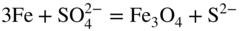
16.2 Coal‐Fired Boilers
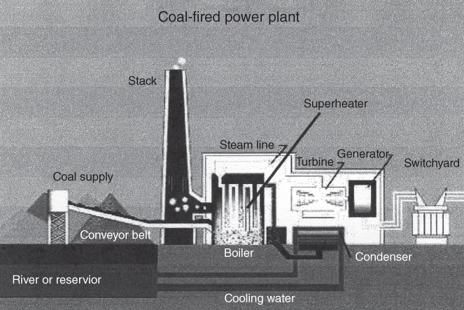
Type of fuel
Typical salt deposits
Waste
ZnCl2, PbCl2, KCl, NaCl
Straw
KCl, K2SO4
Wood
KCl, K2SO4, NaCl, Na2SO4
Coal
Na2O4, K2SO4, (Na,K)2Fe(SO4)3
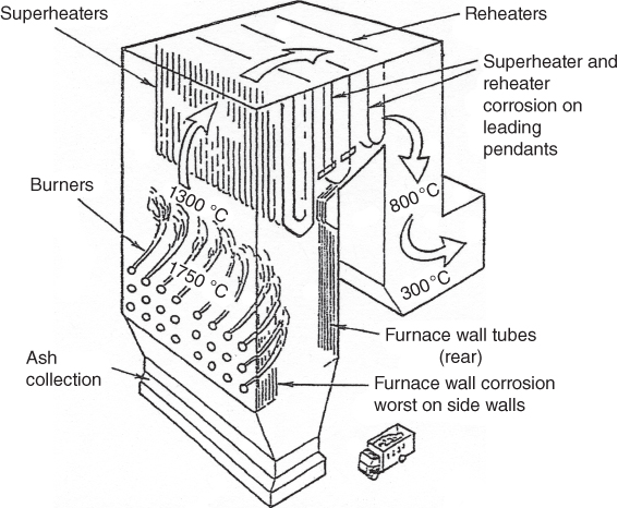
Coal type
Property
Anthracite
Illinois #6 bituminous, Illinois
Spring Creek subbituminous, Wyoming
Bryan lignite, Texas
Approximate composition (%)
Moisture
7.7
17.6
24.1
34.1
Volatile matter, dry
6.4
44.2
43.1
31.5
Fixed carbon, dry
83.1
45.0
51.2
18.1
Ash, dry
10.5
10.8
5.7
50.4
Composition (%)
Carbon
83.7
69.0
70.3
33.8
Hydrogen
1.9
4.9
5.0
3.3
Nitrogen
0.9
1.0
1.0
0.4
Sulfur
0.7
4.3
0.4
1.0
Oxygen
2.3
10.0
17.7
11.1
Ash
10.5
10.8
5.7
50.4
Thermal properties
Heating value (as received) Btu/lb
11 890
10 300
9 190
3 930
Ash fusion temperatures (reducing atmosphere) (°F)
Initial deformation
—
1 930
2 100
2 370
Softening
—
2 040
2 160
2 580
Fluid
—
2 700
2 700
2 900+
Ash analysisa (%)
SiO2
51.0
41.7
32.6
62.4
Al2O3
34.0
20.0
13.4
21.5
Fe2O3
3.5
19.0
7.5
3.0
TiO2
2.4
0.8
1.6
0.5
CaO
0.6
8.0
15.1
3.0
MgO
0.3
0.8
4.3
1.2
Na2O
0.7
1.6
7.4
0.6
K2O
2.6
1.6
0.9
0.9
P2O5
—
—
0.4
—
SO3
1.4
4.4
14.6
3.5
Mineral species
Formula
Kaolinite
Al2O3·2SiO2·H2O
Illite
K2O·3Al2O3·6SiO2·2H2O
Biotite
K2O·MgO·Al2O3·3SiO2·H2O
Orthoclase
K2O·Al2O3·6SiO2
Albite
Na2O·Al2O3·6SiO2
Calcite
CaCO3
Dolomite
CaCO3·MgCO3
Siderite
FeCO3
Pyrite
FeS2
Gypsum
CaSO4·2H2O
Quartz
SiO2
Hematite
Fe2O3
Magnetite
Fe3O4
Rutile
TiO2
Halite
NaCl
Sylvite
KCl
Element
Oxide
Melting point, °C (°F)
Compound
Melting point, °C (°F)
Si
SiO2
1715 (3120)
Na2SiO3
877 (1610)
Al
Al2O3
2043 (3710)
K2SiO3
977 (1790)
Ti
TiO2
1838 (3340)
Al2O3·Na2O·6SiO2
1099 (2010)
Fe
Fe2O3
1565 (2850)
Al2O3·K2O·6SiO2
1149 (2100)
Ca
CaO
2521 (4570)
FeSiO3
1143 (2090)
Mg
MgO
2799 (5070)
CaO·Fe2O3
1249 (2280)
Na
Na2O
Sublimes at 1277 (2330)
CaO·MgO·2SiO2
1391 (2535)
K
K2O
Decomposes at 349 (660)
CaSiO3
1540 (2804)
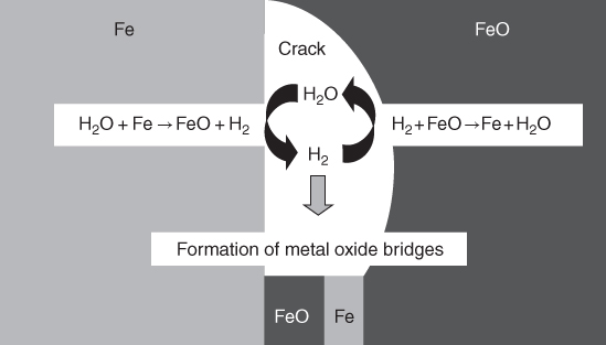
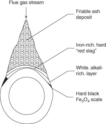
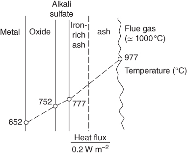
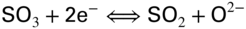


 and/or SO3, we can write
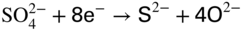
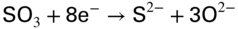


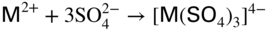
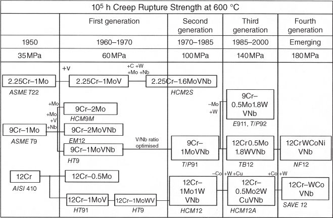
Concentration in wt%
105 h Creep rupture stress
Type of material
Cr
Ni
Coefficient of thermal expansion (10−6 K−1)a
Thermal conductivity at 650 °C (W m−1 K−1)
650 °C
550 °C
Hot corrosion weight loss at 650 °C/5 hb
Ferritic–martensitic P91
9
—
12.7
30
48
162
>40
Austenitic AISI 347H (1.4961)
17
13
18.6
24
64
170
17
Austenitic Alloy 800
20
32
17.3
22
60
200
10
Ni‐based IN617
22
Bal.
14.4
23
160
–
10
16.3 Coal‐ash Corrosion


Designation
Elements detected
Remarks
Layer I
Cr, Fe, Ni, Mo, O, S, K
Cr sulfide is predominant
Mo is concentrated
K is penetrated between slides and scales
Layer II
Cr, Ni, Fe, O, Mo, S
(Mo and S exist only in the interface of Layer I)
Cr oxide is predominant
Ni sulfide is formed in the interface of Layer I
Layer III
Fe, O, K, Ni, S, Al
Fe oxide is predominant
Layer IV
Ca, Fe, Mg, Al, Si, K, O, S
Ca sulfate is predominant
Layer V
Fe, Al, Si, Ca, Mg, K, O, S
Fe, Al, and Si oxides are predominant 

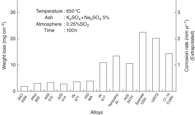
16.4 Oil‐Fired Boilers

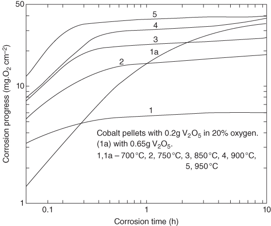

 is the weight change per square centimeter at time t and k is the velocity constant. This relation, derived for a diffusion‐controlled corrosion process, holds good for the initial stages of corrosion of iron, cobalt, titanium, molybdenum, and tungsten in the presence of moderate excess of molten vanadium pentoxide. Nickel is found to obey a simple semilogarithmic law, as might be expected for a process governed by diffusion through the corrosion layer. Chromium is the most resistant of all metal studies reported in the open literature.


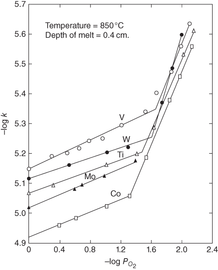
Exponent of oxygen pressure
Process

Depth of melt (cm)
Activation energy (kcal)
Experimental action constant Ak (corrected)
High pressure
Low pressure
VO2.5 ⇔ VO2 + 1/4 O2
—
—
25.6
—
—
—
VO2 + 1/4 O2 → VO2.5
1.0
—
16.8
(0.754)
0.083
0.83
0.098
0.91
0.102
0.91
0.1
—
16.3
—
—
—
0.05
—
16.3
—
—
—
0.01
—
3.4–9.8
—
—
—
Conductance
1.0
—
17.2–25.9
—
0.24
0.59
Viscous flow
1.0
—
10.1
—
—
—
Diffusional corrosion
1.0
—
14.7
—
—
—
Corrosion of Co
1.0
0.4
27.0
1.150
0.083
0.71
0.2
0.3
26.5
1.189
—
—
Corrosion of Fe
1.0
0.4
21.2
0.069 4
0.11
0.91
0.008 69
0.4
7.4
2.67 × 10⁻⁶
—
—
Corrosion of Ti
1.0
0.4
24.0
0.143
0.091
0.59
Corrosion of W
1.0
0.4
28.2
0.796
0.077
0.83
Corrosion of Mo
1.0
0.4
18.3
0.012 76
0.1
0.77
0.2
0.4
18.4
0.017 01
—
—
Corrosion of V
1.0
0.4
16.5
0.004 56
0.12
0.71
1.0
0.8
16.5
0.004 58
—
—
0.008 69
0.4
8.9
4.81 × 10⁻⁶
—
—
Corrosion of Ni
0.2
0.4
27.9
(2971)
0.15
1.67

Activation energy (kcal)
Metal
Rate law
Velocity constant (g cm−2 s−1) (850 °C; O2; 0.4 cm depth of melt)
Primary oxidation product
Volume ratio
Free energy of formation ΔG1123 (kcal)
Vanadic corrosion
Corrosion in pure oxygen
Fe
Linear
12.3 × 10⁻⁶
FeO
1.7
−45.3
21.2
22.4
Co
Linear
12.0 × 10⁻⁶
CoO
1.86
−36.9
27.0
20.0
Ti
Linear
8.6 × 10⁻⁶
TiO
1.20
−98.4
24.0
24.3
Mo
Linear
9.3 × 10⁻⁶
MoO3
3.3
−94.2
18.0
—
W
Linear
7.6 × 10⁻⁶
WO3
3.35
−133.5
28.2
44.0
V
Linear
7.2 × 10⁻⁶
V2O5
3.19
—
16.5
—
Ni
Logarithmic
1.4 × 10⁻⁶
NiO
1.65
−42.0
27.9
34.7 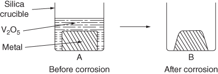
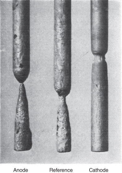
Metal
Action constant (Ak)
Action constant for inward diffusion of oxygen (A1)
Action constant for outward diffusion of oxidation products (A2)
V
0.004 57
0.004 57
—
Co
1.150
0.004 57
0.004 58
Fe
0.069 4
0.004 57
0.004 88
Ti
0.143
0.004 57
0.004 71
W
0.796
0.004 57
0.004 59
Mo
0.012 76
0.004 57
0.007 1


16.5 Corrosion in Waste Incinerators

16.6 Plant Experience with Fireside Corrosion
16.6.1 British Experience
SiO2
46–53
Al2O3
24–33
Na2O
0.7–3.3
K2O
2.4–3.9
MgO
1.0–2.0
Fe2O3
7.6–12.0
TiO2
0.9–1.1
CaO
1.0–6.0
SO3
0.3–2.0

16.6.2 Danish Experience
Equipment
Material
Steam temperature
Furnace
Mild steel/15Mo 3
<400 °C
Superheater
1st stage
13Cr Mo44 ≈ 1Cr 1/2Mo
<510 °C
2nd stage
10Cr Mo910 ≈ 2 1/4Cr 1Mo
x20Cr Mo V12.1 ≈ BS 762
(x9Cr Mo91 ≈ 9Cr 1Mo)
(AISI 316)
Up to 545 °C
Reheater
1st stage
13Cr Mo44 ≈ 1Cr 1/2Mo
<510 °C
2nd stage
10Cr Mo910 ≈ 2 1/4Cr 1Mo
x20Cr Mo V12.1 ≈ BS 762
(x9Cr Mo91 ≈ 9Cr 1Mo)
(AISI 316)
Up to 545 °C
16.6.3 Dutch Experience
Steel type
Maximum allowable service temperature (°C)
0.5Mo
530
1Cr 0.5Mo
550
2.25Cr 1Mo
580
12Cr 1MoV
615
347H
>615
Origin
SR
B/A
ST (°C)
Slagging tendency
Australia
90–99
0.05–0.09
1475–1650
Very low
US
78–87
0.12–0.21
1450–1550
Low
Germany
80
0.21
1475
Low
Poland
71
0.32
1275–1300
Moderate
Type
Manufacturer
Main composition
%Cr
%Ni
%Si
347H (reference)
Sandvik
18
10
0.6
Esshete 1250/AISI 310 (outside)
T.I.
26
20
1.2
800H/Tp 446 (outside)
Sandvik
27
—
0.5
1714CuMo/NAC 35CrA (outside)
Nippon Kokan
35
45
0.03
Inco 800H/Inconel 671 (outside)
INCO
46
54
—

16.6.4 German Experience
16.6.5 Japanese Experience
Capacity
550 ton h−1
Steam pressure
173.5 kg cm−2
Steam temperature
569 °C (superheater outlet)
541 °C (reheater outlet)
Type
Single drum, natural circulation
Ash fusion temperature (°C)
Approximate analysis (%)
Ultimate analysis (%)
Reducing atmosphere
Ash composition (%)
Inherent moisture
1.6
Carbon
54.3
Initial def.
1170
SiO2
51.5
Fixed carbon
33.3
Hydrogen
4.0
Softening
1200
Al2O3
23.6
Volatile matter
33.5
Nitrogen
0.8
Hemisphere
1240
Fe2O3
8.23
Ash
31.6
Oxygen
6.1
Fluid
1340
TiO2
1.96
Sulfur
3.2
CaO
9.82
MgO
1.57
Na2O
2.34
K2O
1.18
SO3
2.87
Tube no. 28
Tube no. 49
Chemical composition (%)
SiO2
3.30
4.07
Al2O3
1.62
1.70
Fe2O3
19.6
15.4
CaO
0.40
0.50
MgO
0.07
0.09
Na2O
0.12
0.16
K2O
0.09
0.10
TiO
0.07
0.08
SO3
2.48
2.49
FeS
68.7
70.8
Ash fusion temperature (°C)
Initial def.
1100
1130
Softening
1260
1240
Hemisphere
1320
1305
Fluid
1340
1335


16.7 Conclusions
References
Further Reading
Fireside Corrosion
16.1
16.2
16.3
16.4
16.5
16.6
16.7
16.8
16.9
16.10
16.11
16.12
16.13
16.14
16.15
16.16
16.17
16.18
16.19
16.20
16.21
16.22
16.23
16.24
16.25