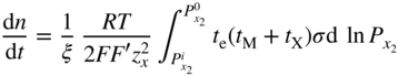
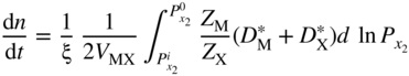
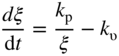
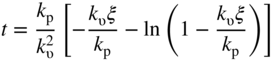
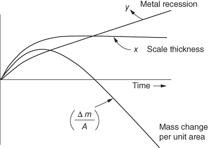
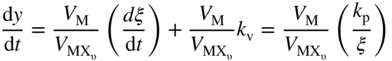
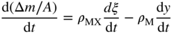
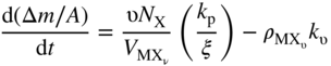
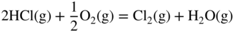
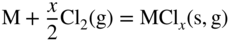
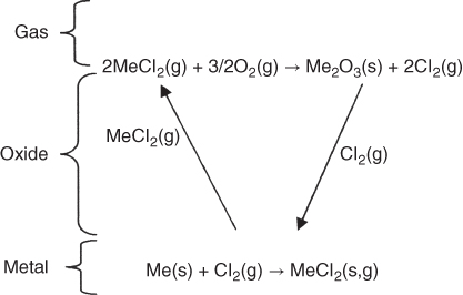
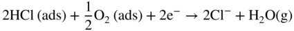
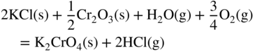
section epub:type=”chapter” role=”doc-chapter”> Halogens and many halogen compounds are very corrosive. In fact, iodine was discovered when, as an impurity in soda ash, it caused corrosion of copper vessels. Hence, materials for containing and handling halogens and corrosive halogen compounds must be selected with particular care. In this chapter, oxidation and corrosion theories are applied to the problems of destructive metal and alloy halogenation. Consideration of halogenation mechanisms is necessary because of the large number of variables involved, including temperature, flow rate, laminar or turbulent nature of flow, halogen partial pressure, diluent gases, active impurity gases such as oxygen, water and halide vapors, abrasion, thermal and mechanical stresses, metal impurities and microstructures, vibration, and radiation. In fact, the practical variations of alloy compositions and environmental conditions are virtually infinite, so that one cannot possibly evaluate all of them in laboratory or pilot‐plant studies. But from some basic laboratory data on reaction kinetics and observations of product morphologies and phases, coupled with an understanding of the scaling and vaporization processes involved, one can anticipate unforeseen problems, determine the cause of existing problems, and design better laboratory tests to evaluate materials for commercial service. Although the corrosion of metals and alloys by pure halogens receives predominant attention in this chapter, we also consider related problems of corrosion by interhalogens, gas mixtures, hydrogen halides, metal halides, and other halogenation agents. Metals may be passivated against halogen attack by deposition of solid reduction products on the metal surfaces: where MX4(s) further blocks rapid M–MX6(v) reaction. On the other hand, such product compounds could accelerate reaction rates. For example, if liquid or volatile oxyhalides or hydrates are formed, they may prevent passivation. The halogen‐metal reaction kinetics is largely influenced by a few pertinent properties of the metal halides, namely, the relative coefficients of thermal expansion for halide and parent metal, the thermodynamic stabilities of condensed and volatile halide species, and halide melting points, vapor pressures, plasticities, electrical conductivities, and ionic diffusion coefficients (Canterford and Colton 1968, 1969). The thermodynamic properties for the halogen–metal reaction can be determined from a knowledge of the standard free energies of formation such as those described in Chapter for several chemical reactions relevant to high temperature corrosion, using JANAF Thermochemical Tables and other sources (Kubaschewski et al. 1967; Reed 1971; Weast 1970). Concerning the melting temperature for the metal halides, one must use a binary phase diagram for ascertaining minimum liquidus temperatures when the reaction products comprise multiple scales, e.g. FeX2 and FeX3 upon the reaction of pure Fe on X2. Likewise, upon the reaction of a binary alloy in an X2 environment, the mixtures of product compounds for each component can establish a liquidus temperature far below those of the constituent compounds. Then, one must consult the pertinent ternary or quasi‐binary phase diagrams (see, for example, the phase diagram for ceramists published by the American Ceramic Society) to establish liquidus temperatures. Concerning the relative diffusion rates, at temperatures above one‐half the melting point, bulk diffusion of halogen and metal ions through the halide scale will be very significant. Using this 0.5 TM–diffusion coefficient relationship, at 150 °C one would expect much more rapid SnF2 (TM = 212 °C) scale formation on tin than MgF2 (TM = 1263 °C) scale formation on magnesium, providing that scale growth rates are diffusion limited in both cases. Concerning the vapor pressures, there are recommended Turkdogan’s and Kellogg’s methods (Turkdogan 1964; Kellogg 1966) for the analysis of equilibrium vapor pressures for vapor species that differ in composition from the condensed phase. In general, the methods used to study metal halogenation kinetics are the same as those used to study metal oxidation kinetics. These include a manometric or pressure‐drop method, several gravimetric methods, the photometric procedure, the electrical resistance method, and the quartz crystal microbalance. The Royal Society of Chemistry (RSC, UK) and the American Chemical Society (ACS, USA) provide good monographs on the topic, which also contain extensive bibliographies on chlorine and other halogens handling procedures and precautions. When a metal or alloy reacts with halogen gas to form a solid product, the product may physically separate the two reactants. This circumstance acts to slow the reaction rate if the product phase is compact and free of macroscopic cracks and voids. On the other hand, cracked or porous scales allow ingress of halogen molecules and reduce the degree of protection. One must also account for dissolution of the nonmetal into the metal and the evaporation of the scale. Thus, the rate of scale growth or metal recession depends greatly upon chemical, physical, and mechanical properties of the intervening product scale. The sealing behavior of pure metals and alloys in oxygen (and air) environments is available in Chapter , and this can be used to interpret scale growth in metal‐halogen systems. Theoretical and experimental studies described in the literature will help in the understanding and control of metal‐halogen reactions. As a base metal surface is exposed to an oxidant, an adsorbed film of a specific structure is set up. With a highly efficient capture of incident molecules, the adsorbed state progresses rapidly to a stable film (several angstroms thick), at which time the growth rate slows because either (i) cations, anions, or electrons are effectively immobile in the film or (ii) cations or anions are hindered at the metal/film or at the film/gas interface, respectively, from entering the scale. At the film/gas interface, dissociated oxidant molecules (i.e. atoms) are reduced when tunneling electrons are trapped to provide an excess of negative surface charge. The resulting electric field across the growing film provides (i) a reduction in the potential energy barriers required for the diffusion of ions or for the tunneling of electrons across the film and/or (ii) a reduction in potential energy barriers for the insertion of ions into the oxide. Various authors differ on the selection of the rate‐limiting step. If the rate of ionic or electronic diffusion or ionic insertion depends upon the electric field (dφ/dx) provided by adsorbed oxygen ions, then for a constant, equilibrium‐adsorbed state, the driving force (reduction in barriers) of the electric field decreases in importance as the film thickens to become a thin scale (from tens to hundreds of angstroms). But at the same time, the morphological restructuring of the scale is contributing in a similar manner. Theories based on these considerations lead either to a logarithmic rate equation [y = ke (te + at)] or to an inverse logarithmic kinetic expression [(l/y) = b − ki,l. ln t]. In the plotting of the kinetic data, one cannot usually distinguish between these rate “laws.” Data for halogenation of metals at low temperatures can frequently be fit to logarithmic expressions. Wagner (1973) has treated the more difficult cases of scale growth in the thin‐film range whereby an electrical charge localized to one interface is compensated by a diffuse charge distributed throughout the scales (as opposed to compensation by an opposing charge at the opposite interface). This treatment provides complicated expressions for the expected kinetics. During the early stages of scale formation and for intermediate temperatures such that T/TM ≤ 0.6, the incoherent crystalline boundaries and line defects set up short‐circuit diffusion of ions through the thin scale, and these can account for scaling rates that are higher by several orders of magnitude than those expected from the extrapolation of kinetic data from higher temperatures. Support for the importance of short‐circuit diffusion in the intermediate temperature range is gained from the response of scaling kinetics to vacuum “aging” of the scale, i.e. the interruption of the steady‐state, rapid scale growth by the removal of the oxidant to allow annealing and grain growth in the scale. When the predominant ionic defects in a compact scale are cation vacancies, the growth of a protective layer occurs by the outward diffusion of cations with a counterflow of vacancies and positive holes. Likewise, scale also forms at the scale/gas interface when the diffusion of interstitial cations and electrons predominate. If the predominant defects were anion interstitials (plus positive holes) or anion vacancies (plus electrons), a compact scale would grow at the metal/scale interface. At high temperatures of corrosion, Wagner (1933, 1936) has described the diffusion‐controlled parabolic growth of a compact one‐phase layered scale on a pure metal to obtain the result where dn/dt is the rate of growth of an MX scale in mol cm−2 s−1; ξ is the instantaneous scale thickness; zx is the valence of the anion; te, tM, and tX are the electrical transference numbers of electrons, cations, and anions; σ is the total electric conductivity of the scale formed; To explain the growth of a compact one‐phase layered scale that exhibits predominant electronic conduction, te > (tM + tX), Wagner (1951) has converted Eq. 11.2 as follows: where VMX is the molar volume of the product compound and through the relation where km represents the quantities in parentheses in either Eq. 11.2 or 11.3. While the validity of Wagner’s theory for the growth of oxide scales has been frequently checked by comparison of experimental values of kp with calculated values of km through Eqs. 11.2 and 11.5, comparable use of this possibility has not been made for the analysis of halogenation reactions. Obviously, these equations provide the basis to predict the dependence of kp on both temperature and Because a number of halides exhibit predominant ionic conduction (Rapp 1970), the phenomenon of local cell action can contribute to the consumption of a metal by halide scale formation as observed by Ilschner‐Gench and Wagner (1958). The established electronic short circuit leads to an overgrowth formation that should be anticipated whenever the corrosion product is a predominant ionic conductor. The relatively high vapor pressures of the halide compounds that form as surface products cause the loss of molecules from the scale to the vapor at the same time that the scale is growing by diffusional transport. Tedmon (1966) described the oxidation rates of pure chromium and Cr2O3− forming Fe–Cr alloys at temperatures greater than 1100 °C as the sum of a parabolic diffusion‐controlled scale thickening and a time‐dependent vaporization loss. The rate equation for the thickening of the scale is where ξ is the scale thickness, kp is the parabolic rate constant for the diffusion step, and kυ is the linear rate constant for the vaporization step. For short times or thin films, Eq. 11.6 predicts parabolic behavior; however, with continued growth, the two terms on the right‐hand side of Eq. 11.6 approach each other so that a steady‐state scale thickness, ξs.s., equal to kp/kυ, is approached. The integration of Eq. 11.6 for ξ = 0 at t = 0 yields the result This functional dependence of ξ on t is schematically illustrated in Figure 11.1. Figure 11.1 Parabolic scale growth with linear evaporation of halide scales. In the consideration of metal recession, y, the metal is consumed both by an increase in ξ and by scale vaporization: where VM and To interpret gravimetric kinetics for the growth of an MXν compound scale, the rate equation must account for the weight gain for the net scale present minus the weight loss resulting from metal recession: where ρM and where NX is the atomic weight of the nonmetal. A quantitative evaluation of recession of gravimetric kinetics to obtain the fundamental rate constants kp and kυ must proceed via numerical methods through integration of Eq. 11.8 or 11.10 after substitution of ξ from Eq. 11.7. In any case, as ξs.s. is attained, the rates of both metal recession and weight gain correspond solely to the linear rates of evaporation. This behavior is schematically illustrated in Figure 11.1. Another important process that occurs during scale growth at high temperatures concerns the simultaneous evaporation of scales and the reactive evaporation of metal. But many factors complicate the morphological and kinetic behavior of scale formation in this condition; therefore we will not review it here. When the predominant ionic defects in a scale are vacant cation sites, then a compact protective layer grows by outward diffusion of cations with a counterflow of vacancies and positive holes. As the scale thickens, its resistance to plastic deformation increases, particularly at points of constraint such as the edges and corners of a specimen. With the continual arrival of vacancies through the scale to the metal/scale interface, the reduced plasticity of the scale can lead to the condensation of vacancies to form voids and ultimately a porous zone at the metal/scale interface. The formation of this duplex scale morphology, with compact columnar grains at the external surface and a porous zone at the metal/scale interface, is favored: (i) at lower temperatures where scale plasticity is lower; (ii) for impure metals (or dilute alloys) containing more reactive solutes, because the formation of a product compound as an internal precipitate within the metal matrix could occur; (iii) for metals containing impurities that form volatile compounds with the reactant gas (e.g. hydrogen or carbon in halogenation reactions); and (iv) at specimen corners and edges where geometrical constraints oppose plastic deformation of the scales. The principal detriment of duplex scale formation is the resulting poor scale/metal adhesion, which leads to scale cracking and exfoliation particularly upon thermal cycling. When the predominant ionic defects in a scale are vacant anion sites or anion interstitials (as in the case for FeF2, for example), then the diffusional growth of a product scale occurs by the inward diffusion of anions with an equivalent transport of positive holes or electrons. The new scale forms at the metal/scale interface beneath the previously formed scale. Because the products of reaction generally comprise more volume than the consumed metal, the scale must deform plastically to accommodate the volume increase, or else tensile stresses are introduced into the external surface of the outer scale and cause it to fracture. Particularly at corners and edges, plastic deformation is restricted as the scale thickens, such that fractures occur and lead to a porous scale through which the molecular reactants can diffuse. As a clean surface of an A–B alloy is first exposed to the reacting X2 gas at elevated temperatures, there is too little time for selecting product formation, and the alloy simply forms the product compounds of each of the alloy components in a molar proportion equal to that in the bulk alloy (Chattopadhyay and Wood 1970). Then the reaction kinetics at short times are likely to be higher than those subsequently experienced during the steady‐state growth of the protective BνX scale. At short times, the tiny grains of the thin initial duplex scale each grow according to their individual transport rates such that the faster‐growing product (often the less stable AχX compound) overgrows the slower‐growing product (usually the more stable BνX compound). As a result of the depletion of A, the underlying BνX grains grow laterally to ultimate impingement at the metal/scale interface. In this way, the steady‐state protective scale of BνX may be found beneath an external AχX scale whose supply and growth are stopped after the underlying scale is established. When scale vaporization is important, as in the halogenation of alloys, the transient reaction stage might be used to place a less volatile, more noble compound on top of a more volatile, but slower‐growing, less noble compound. After sufficient time, of course, the outer scale could be lost completely by vaporization. Concerning the selective oxidation of metal alloys, let us consider a binary solid solution alloy A–B for which the lowest compound BνX of component B is more stable (has a more negative Data on alloy oxidation show that the steady‐state parabolic growth of a protective scale can be quite dependent upon the presence of aliovalent solutes (dopants) dissolved in the scale. Such solute ions differ in ionic charge (or lattice position) from the cations or anions of the host compound and are therefore electrically active. Because gross electrical neutrality is required for a growing scale, the summation of the relative charges for negative ionic defects (cation vacancies or anion interstitials) and electrons and negative dopants equals the summation of the relative charges for positive ionic defects (interstitial cations and anion vacancies) and positive holes and positive dopants. Obviously in this electrical neutrality condition, the concentration of the ionic defect whose transport accounts for scale growth is a prominent term that is balanced by the defects of opposite charge. By the introduction into the host compound (scale) of a soluble aliovalent dopant of the same sign of charge as the most mobile ionic defect, the concentration of this defect will be reduced drastically according to well‐established defect equilibria conditions (Kröger 1964). Reduction of the concentration of the fastest ionic defect species obviously reduces the diffusive flux of this species and the scaling rate of the alloy as well. This discussion presumes that the scale is a predominant electronic compound. When the scale is a solid electrolyte, the scaling rate should be lowered as the concentration of the predominant electronic species is lowered through doping. To design alloys intended for service in halogens on the basis of the doping effect, one must know at least the identities (and hopefully the concentrations) of the predominant ionic and electronic defects in the compound (scale) of the pure metal. One must know that the intended dopant ion is sufficiently soluble and has a certain electrical charge in the host lattice. Finally, for the reaction scheme under consideration, the dopant must reach the scale in a manner such that dissolution should occur. More detail of the response of alloys to atmospheres based on Cl2, O2–Cl2, and corresponding fluorine atmospheres is given by Lai (1990). Because nickel, copper, iron, aluminum, and their alloys are commonly used structural materials, studies of halogen attack on these metals are largely reported in the literature (Fontana and Staehle 1980; Han and Cho 2002). Laboratory studies of halogen attack on other metals (chromium, silicon, etc.) and alloys (low‐alloyed ferritic steels, ferritic–martensitic steels, austenitic stainless steels, nickel‐based alloys, etc.) are also being reported including observed reaction kinetics, postulated reaction mechanisms, and important experimental parameters such as temperature, halogen gas pressure and flow rate, and metal and gas purities (Kuiry et al. 1996; Maloney and McNallen 1983; Oh et al. 1986; Stott and Shih 2000). The halogenation of many metallic materials covers wide temperature ranges and is identified in many industrial environments for the processing of metallurgical ores, calcining operations, chemical processing streams, manufacture of fluorine‐containing compounds, production of uranium, and so on. In many high temperature industrial processes where fuels and/or feedstocks are often contaminated with impurities, such as alkaline metals, halogen may readily react with these metals to form halide salts. Corrosion reactions under these conditions are discussed in chapters dealing with high temperature corrosion in gas turbines, coal‐fired boilers, oil‐fired boilers, and so forth. Waste‐fired boilers suffer severely from corrosion of critical components such as superheater tubes, when operating in high temperature environments exposed to alkali, chlorine, sulfur, and other gaseous species, in the temperature range 400–700 °C. This is a pertinent case requiring a review here, due to the large application of superheater tubes and the know‐how that we can require, under the point of view of materials, corrosion, and its mitigation, when studying such a situation. A number of different materials are commonly used for superheater tubes, and these include 13CrMo44 (1Cr–0.5Mo–Fe) and 13CrMo910 (2.25Cr–1Mo–Fe) low‐alloyed ferritic steels, 9–12% Cr ferritic–martensitic steels, HCM 12A that is a martensitic 12%‐Cr steel containing about 35% delta ferrite, standard 304 austenitic stainless steel with 18% Cr–8% Ni–Fe, other steels in the AISI 300 series, nickel‐based alloys such as Inconel 625 with 22% Cr–9% MoNi, etc. The superheater tubes face a highly complex atmosphere with both corrosive flue gas and deposits. In studies by Grabke et al. (1995) and Zahs et al. (1999, 2000), the main reason for alloy breakdown was considered molecular chlorine, formed from hydrochloric acid in the flue gas. In addition to the gaseous species, impaction of various solid particles and condensation of gaseous compounds onto the slightly cooler heat exchangers adversely affect alloy performance. Deposit formation is a topic on its own (Baxter 1993) but cannot be ignored since these deposits are a major cause for corrosion breakdown. Studies by Grabke (1995), Pettersson et al. (2006a), and Kawahara (2002) identified the following crystalline compounds within the deposit by XRD (X‐ray diffraction): NaCl, KCl, CaSO4; NaCl, KCl, CaSO4, SiO2; and (K, Na)Cl, K2SO4, Na2SO4, (K, Na)2Ca2(SO4)3, Ca2MgSi2O7. These corrosion products clearly show that the superheaters suffer from deposit‐induced corrosion, involving oxide degradation in the presence of molten salts, the effect of sulfur/chlorine ratio in the fuel, and the effect with the chlorine‐containing compounds as the major reason for rapid attack (Asteman et al. 2000; Ebbinghaus 1993; Giggins and Pettit 1980; Young 2008). During combustion of waste and some types of biomass, high levels of HCl, NaCl, and KCl are released. In atmospheres containing both HCl and O2, accelerated corrosion has also been observed, and a common opinion is that Cl2 forms according to the Deacon reaction (Nieken and Watzenburger 1999): This is normally a very slow reaction but could be catalyzed by the oxidized metal surface. During combustion of waste, alkali chlorides are deposited on the superheater tubes, and chlorine formation may take place according to Considering the thermodynamics of the M–Cl–O system, metal oxides are stable at high oxygen partial pressures, while metal chlorides can be expected in regions with low oxygen partial pressures. Chemical analyses of corrosion products formed in oxidizing–chlorinating environments have confirmed this behavior in that metal chlorides are usually observed at the metal/scale interface (low oxygen partial pressure), while the outer part of the scale (high oxygen partial pressure) contains mainly metal oxides. In other words, there seems to be an inward diffusion of chlorine through the scale and a subsequent accumulation at the metal/scale interface. It has been suggested that this implies a molecular transport in order not to have chlorine diffusion across a chlorine activity gradient (Kofstad 1988). In this case, the molecular chlorine must diffuse through the oxide layer, presumably through cracks and pores. In an O2–Cl2 environment, the stability of metal oxides and chlorides depends on the partial pressure of oxygen and chlorine. At the metal–oxide interface, the oxygen pressure is low and metal chlorides are stabilized. These are formed according to At elevated temperatures, the vapor pressure of metal chlorides can be significant, and volatile chlorides will diffuse toward the oxygen‐rich outer part of the scale where they are destabilized according to The detrimental effect of chlorine and how it accelerates corrosion has been frequently studied, and the degradation process is often termed active oxidation. The name refers to the loose porous layer that is created, providing little or no protection. In this reaction, metal oxides are formed while chlorine is released, as Eq. 11.14 shows, and may again penetrate the oxide scale, creating a cycle. The essence of this is the continuous transport of metals away from the metal surface while little, or no, chlorine consumption exists. This is often referred to as the chlorine cycle, schematically illustrated in Figure 11.2 (Rees and Grabke 1992). Figure 11.2 Schematic drawing of chlorine cycle as described by Reese and Grabke (1993). Although the chlorine cycle is frequently used for describing corrosion in oxidizing–chlorinating environments, there are concerns with this model. For example, Folkesson et al. (2007) suggested that the transport could be ionic and electrochemically driven. The mechanism would then be explained by HCl dissociating at the scale/gas interface according to the cathodic process: A corresponding anodic process at the metal–oxide interface creates outward diffusing cations. The transport of chlorine through the oxide scale would thus be ionic rather than gaseous, at least during the initial stages. Although the metal chloride is thermodynamically unstable at the scale/gas interface, studies have shown the presence of metal chlorides at the surface. Jacobson et al. (1989) performed work with mass spectroscopy showing that volatile metal chlorides and metal oxychlorides are lost to the gas flow during exposure in chlorine‐rich environments. Stott and Shih (1966) proposed that Tedmon (2000) behavior is evident with a weight gain due to metal oxide formation in simultaneous with a weight loss due to vaporization of volatile metal chlorides. It is evident that chlorine interferes with the oxide formation, creating volatile corrosion products as well as porous and poorly protective oxide scales. Breakdown of metal oxides due to formation of other thermodynamically more stable corrosion products is also possible. Alkali chlorides, sulfates, and carbonates are constantly being deposited on the superheater tubes during operation. Pettersson et al. (2006b) have studied the reaction between solid and gaseous potassium chlorides with an oxide. The authors found that a protective chromia scale will react with the alkali‐forming potassium chromate according to Chromates are very stable compounds and may also form by the reaction between Cr2O3 and NaCl or K2CO3. The formation of chromate may deplete the oxide in chromium and cause the formation of iron‐rich oxides and mixed spinel oxides, which are considered poorly protective. The breakdown of chromia scale may thus initiate accelerated corrosion attack by facilitating, for example, chlorine ingress through the scale. Several metal halogenation studies have been conducted along the last decades, but most of the information about halogen resistance of the metals comes from cursory comparisons of commercial metals and alloys. Scale morphologies, defect structures, impurity doping effects, self‐diffusion coefficients, solubilities and diffusivities of the halogens in metals, and even kinetics (extensively studied in metal oxidation research) have been much neglected in studies of metal halogenation. Some studies have, in part, been discouraged by the highly toxic and corrosive nature of halogens. A knowledge of the above‐discussed metal and metal‐halide scale properties and an understanding of corrosion mechanisms provide the basis for the designing and engineering of corrosion‐resistant alloys. This idea of alloy design (used, for example, to develop alloys resistant to high temperature oxidation and hot corrosion) rather than simple alloy evaluation has not generally been applied to develop halogen‐resistant alloys. Such alloy design could be very productive. Long‐term forecasting of the behavior of halogen‐metal systems and the development of halogen‐resistant alloys are facilitated by a knowledge of metal‐halide defect structures, self‐diffusion coefficients, thermodynamic properties, electrical conductivities, and physical properties and a knowledge of alloy self‐diffusion and fluorine solubilities. Considerable thermodynamic data are already available, but other data are particularly sparse. It is hoped that future studies of metal halogenation will provide this information along with more detailed observations of scale morphology than have been provided in the past. In the present chapter, some important aspects of high temperature halogenation during waste combustion have also been identified. On a fundamental level, the corrosion breakdown in chlorinating–oxidizing atmosphere is interesting to study. HCl‐induced corrosion could be analyzed in more detail with some advanced techniques such as high temperature mass spectroscopy to analyze different volatile species and quantify their impact on the corrosion attack. More detailed post‐exposure analyses with scanning electron microscopy (SEM) and transmission electron microscopy (TEM) may be helpful in understanding the interaction between chlorine and the various alloying elements and how this affects the scale growth. In full‐scale boilers, optimizing the alloy performance and therefore the efficiency is the main goal, and here the beneficial effect of changing alloy composition as well as flue gas composition was shown. Combining these strategies could possibly further improve alloy performance. With better control of flue gas chemistry, the deposition of aggressive compounds onto superheater tubes can be better controlled and as a consequence makes suitable alloy selection less challenging. However, this requires large test campaigns in full‐scale boilers with long‐term exposures under various conditions.
Chapter 11
Halogenation
11.1 Introduction

11.2 Metal–Halogen Reactions
 and
and  are the nonmetal activities at the metal/scale and scale/gas interfaces, respectively; and F and F′ are differing values for the Faraday constant having their appropriate units. Equation 11.2 shows that the growth of a compact scale can essentially be limited by the transport of electrons when (tM + tX) > te (when the scale is a solid electrolyte) or by the transport of ions when the scale exhibits predominant electronic conduction. For many halides, the partial electrical transference numbers have been established as a function of
  .
.
 and
and are the self‐diffusion coefficients for the cation and anion, respectively. These expressions for instantaneous scaling rate can be used for comparison with kp, the gross parabolic scaling rate constant, defined by

 (Wagner 1936). For the formation of compact oxide scales on copper, nickel, cobalt, iron, and manganese, good agreement between kp and the calculated km has been found at sufficiently high temperatures, i.e. at about 1000 °C or T/TM (scale) > 0.75. Experimental activation energies and
  dependencies for parabolic oxidation also agree with the predicted values.
 are the molar volumes of the metal and the MXν scale, respectively.
 are the bulk densities of the metal and the scale, respectively. The combination of Eqs. 11.6, 11.8, and 11.9 gives
11.3 Alloy–Halogen Reactions
 ) than the lowest compound AχX of component A. Generally, the selective oxidation of the less noble component B is manifested in one of two limiting product morphologies (Douglass 1971; Rapp 1965; Wagner 1959): (i) for sufficiently dilute concentrations of B in A–B (often less than about 10 at.% B), tiny precipitates of BνX are formed at an internal reaction front in the alloy beneath a scale of AχX if the permeability (solubility times diffusivity) of X dissolved in A is much greater than the product of the diffusivity times the bulk content of the reactive solute, or else (ii) for greater solute B contents (often greater than about 20 at.% B) or for alloys in which the nonmetal atoms are essentially insoluble, the compound BνX will form the predominant external scale layer on the A–B alloy. Intermediate behavior, e.g. internal precipitation, is several times observed and can be important to the science and technology but will not be detailed here.
11.4 Laboratory Studies


11.5 Conclusions
11.6 Questions
References
Further Reading
Halogenation
11.1
11.2
11.3
11.4
11.5
11.6
11.7
11.8
11.9
11.10
11.11
11.12
11.13
11.14
11.15
11.16