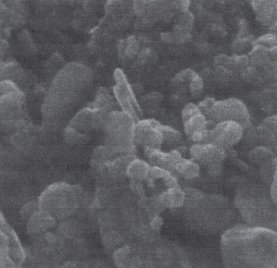
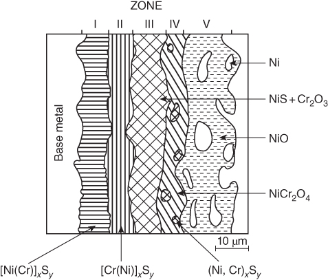
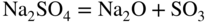
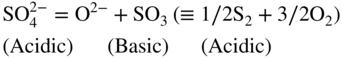
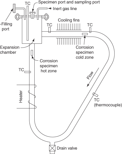
section epub:type=”chapter” role=”doc-chapter”> Alloys for high temperature application usually contain appreciable quantities of nickel: in particular, alloys based on the 80–20 nickel–chromium system have proved extremely successful because they can combine strength with good oxidation resistance at high temperatures. However, in gas turbine applications, where the products of combustion of the fuel used condition the atmospheres, oxidation resistance alone is insufficient, and the resistance of the alloys to carburization, sulfur attack, and corrosion by ash must also be considered. Three main types of gas turbine may be listed: (i) aeroengine, (ii) industrial, and (iii) marine. Aeroengines burn clean fuel but ingest impurities in the air intake. This is aggravated in the marine gas turbines since the air intake includes sea salt. Industrial engines burn inferior fuel containing vanadium and sodium, but the air intake can be filtered. Turbine components are made of Ni‐ or Co‐based alloys. The blades and vanes are subject to cyclic temperature corrosion in alkali sulfate oxide ±chloride ±vanadic environment. Advanced turbines operate at high inlet temperatures (1350 °C) and the industrial turbines at 1150 °C. The blades are cooled to 850–900 °C. Catastrophic corrosion occurs at lower temperatures: 610–750 °C for Ni‐based alloys and 750–850 °C for Co‐based alloys. Coatings have been tested extensively in the field of gas turbines, and these include multicomponent alloy compositions and alloy‐ceramic formulas as well as thermal barrier coatings (TBCs). Superalloys form 50 wt% of gas turbine engines, the rest being about equal parts of Ti alloys, steels, and composites. Development trends in the superalloy systems tend toward directional solidification (DS), powder metallurgy (PM), and mechanical alloy processing (MAP). In gas turbines used for aircraft applications, where highly refined fuels are used, corrosion, although still a problem, is usually secondary to stress considerations, but where turbines are used for marine and chemical plant or for production of cheap electrical power, it is often necessary for economic reasons to run on lower‐grade fuels, and these can introduce severe hot corrosion problems. Table 15.1 provides the relevance and importance of hot corrosion in various energy fields and the associated contaminants, which are responsible for the degradation of components during service. Table 15.1 Relevance and importance of hot corrosion in energy systems aMagnetohydrodynamic. Thus, on studying corrosion under turbine conditions, the effects may be broadly divided into two categories, the first being the effect of the gaseous products of combustion and the second the effects of deposits. Sulfur present in the fuel and salt in the marine environment would lead to the formation of sodium sulfate. So it is sodium sulfate with or without sodium chloride (or nitrate) that has been most extensively investigated. However, internal sulfidation called green rot that occurs in a carburizing environment was reported by Hancock (1968) and Strochi et al. (1969), while black plague corrosion found on high‐strength nickel‐based turbine alloys was produced when a very dilute salt solution was injected into downstream air in minute quantities. Fuel quality does not cause “black plague,” which is primarily metallurgical in origin, and is regarded as an oxidation phenomenon as Belcher et al. (1967) report. The object of the present chapter is to review some fundamental aspects of hot corrosion and the behavior of gas turbine materials in the presence of sodium sulfate (with or without sodium chloride), oxygen, and sulfur‐containing gases, which are the contaminants most likely to be commonly encountered in gas turbine environments. The principle of the gas turbine is as follows. Air is drawn into the engine and compressed. Fuel is mixed with the compressed air and burned in a combustion chamber with the object of heating the gas. The hot compressed gas is then expanded through a turbine that extracts the energy from it; part of this energy is used to drive the compressor and the remainder is available for useful work. The maximum temperature in the cycle is the temperature of the gas entering the turbine, and this temperature is determined by the capability of the turbine to accept it. The hottest part of the turbine is the first stage, which consists of a ring of stationary airfoils, called the inlet nozzle guide vanes, and a ring of rotating blades called the first‐stage rotor blades or buckets. The turbine inlet temperature in aircraft gas turbines rose progressively to a maximum of the order of 900 °C. Further increases in turbine inlet temperature were achieved as a result of the introduction of cooling of the vanes and blades using air drawn from the high‐pressure compressor. The earliest alloys used for gas turbines, developed in the 1940s, were based on Nichrome (Ni–20%Cr) heater alloys and the Stellite (Co–10%Ni–35%Cr) supercharger alloys. The strength of the nickel‐based alloys was increased as a result of the introduction of the Ni3(Al,Ti) ordered phase, gamma prime. Increasing the volume fraction of gamma prime in the alloy required that the chromium content be reduced. No phase equivalent to gamma prime exists for cobalt‐based alloys, and the modern cobalt‐based superalloy has changed relatively little from its origins. These early alloys owed their oxidation resistance to the formation of a protective layer of chromia, Cr2O3, on the metal surface. However, a number of the nickel‐based alloys with lower chromium contents also exhibited excellent oxidation resistance due to the formation of protective alumina scales. The components of the first stage of modern gas turbines are now generally coated with an alumina‐rich layer designed to develop an Al2O3 scale. A major corrosion problem with the lower chromium nickel‐based gas turbine alloys was encountered in the early 1960s in aircraft that were being used in missions at low altitudes close to the sea. Under these conditions, a rapid corrosion of the blades and vanes was sometimes encountered, leading to severe destruction of the involved materials. The increasing cost of fuel has resulted in a renewed interest in improving the efficiency of gas turbine systems. In most cases, this involves the modification of the properties of the existing alloys and the production of new materials. A partial listing of companies producing and supplying high temperature alloys is given below. The alloys referred to in this chapter that are produced by a specific company are given in parentheses. Each company produces a more extensive range of high temperature alloys, and a complete listing can be found at the web addresses provided: It has been known for many years that at high temperatures in the presence of salt, heat‐resisting alloys undergo rapid corrosion. This problem was greatly intensified in the 1950s by development in jet engines and the application of nuclear energy. The extremely high temperatures (800 °C and above) encountered in jet engines and gas turbines required the development of new alloys with sufficient resistance to corrosion by the hot combustion gases as well as adequate mechanical properties at the high temperatures encountered. Alloys based on nickel and chromium are well known for their good resistance to oxidation at temperatures in the range of 800–1200 °C. With the demand for improvement in creep properties at elevated temperatures (≈900 °C), alloy compositions have been modified in order to attain these properties. This has been achieved by reducing the chromium content of the alloys, increasing the amounts of some of the elements already present, and introducing new elements. The alloy series – Inconel, Nimonic, Hastelloy, MELCO, and DISCO – are a result of this. Betteridge and Heslop (1974) and Sims and Hagel (1972) have discussed the Nimonic alloys in detail. Rather unexpectedly, these changes in composition have resulted in a susceptibility to a form of high temperature oxidation in which sulfur acts as a promoter and a propagator. This new phenomenon, most severe than the normal sulfur attack and generally referred to as hot corrosion (1967), has been encountered in gas turbines operating in marine environments. It is acknowledged that this form of attack is associated with the unfavorable operating environment. Much research has been carried out on the chemical nature of the deposits and the mechanism of attack that results, but it is apparent from the diversity of opinions held by various workers in the field that the phenomenon was not adequately understood in 1970s (Jaffee and Stringer 1971; Stringer 1977; Seybolt et al. 1967). However, there was general agreement that the corrosion proceeds in three steps: The mechanisms that have been postulated mainly differ in the explanation for the processes occurring in stages 2 and 3. The slag that promotes sulfidation corrosion in a marine gas turbine is formed by the reaction of sulfur in the fuel and sodium from the sea salt ingested through the intake air (DeCrescente and Bornstein 1968). Under the oxidizing or de‐electronizing operating conditions, sulfur in the presence of a sodium salt such as sodium chloride (NaCl) is then capable of forming Na2SO4 via Na2O and SO2/SO3. The ability of NaCl to form sodium monoxide (Na2O) is well demonstrated by Quets and Dresher (1969). As it is known that sulfur dioxide is more effective in converting sodium chloride to sodium sulfate than sulfur trioxide, several workers (Birks et al. 2006) suggested that the transformation of NaCl to Na2SO4 involves the Hargreaves type of reaction, which is the basis of an old process for the manufacture of sodium sulfate (salt cake). The equations for the formation of Na2SO4 might then be or combining these equations As it has been shown by DeCrescente and Bornstein (1968), this reaction, besides being thermodynamically favorable in the temperature range of interest, is quite rapid. Sodium sulfate produced by this means, together with that already present in the sea spray (Schirmer and Quigg 1967), can condense as a slag on the hot engine parts. This concept is supported by the detection of sodium sulfate on parts corroded in service. NaCl itself is almost never found in the deposits, due to its high dew point, but this does not rule out the possibility that impacting NaCl particles onto the alloy surface may play a significant part in the corrosion process. Therefore, as discussed by Condé (1972), NaCl may be one of the principal agents responsible for Na2SO4 hot corrosion. Reaction of a metal surface with its environment can occur only after the protective film is penetrated. In the case of the nickel‐based superalloys, this film is normally a mixture of Al–Ni–O and Cr–Ni–O phases composed mainly of chromium and/or aluminum oxides (Cr2O3 and Al2O3), and, in addition, a pure NiO type of oxide or NiCr2O4 spinel oxide may form (Bergman 1967). Whether Al2O3, Cr2O3, or NiCr2O4 is responsible for protection is the subject of much controversy (see above), but it is widely believed that the major contribution comes from Cr2O3 (Viswanathan 1968). In the presence of a sodium sulfate slag, the oxide film is penetrated, bringing into direct contact the metal surface and the molten salt. The mechanism of film penetration is uncertain, but several possibilities exist (Farrel et al. 1970). One explanation that has enjoyed wide acceptance suggests that chromium oxide (Cr2O3) is dissolved by reactions of the type The events that occur after film destruction are not well understood. Earlier studies on this aspect have been mainly empirical. But, in the 1970s, Condé (1972) suggested that once the protective oxide film is penetrated, sodium sulfate may be reduced, or electronated, according to the following equations: and and where R is an electronizing agent and M, in the case of complex superalloys, is composed of several elements including chromium. NaCl acts as the reducing agent. Early in the 1950s, it was also proposed that Na2SO4 had to be chloride‐contaminated to promote rapid sulfidation attack. Waddams et al. (1969) proposed that Na2SO4 reacts with the base metal at cracks and pores where micro‐electronizing conditions may exist. Many other workers (Birks et al. 2006) report that neither the chloride ion nor externally introduced reducing conditions are prerequisites for hot corrosion. Bergman (1967) and Seybolt (1968) suggest that the depletion of chromium in surface zones through the formation of oxides and sulfides reduces the corrosion resistance of Cr‐depleted zones (nickel‐rich zones), thereby promoting gross oxidation and/or sulfidation. Quets and Dresher (1969) suggest that in order for hot corrosion to occur, there must be a simultaneous reaction between the nickel of the alloy and the oxide of one or more of the alloy ingredients, with sodium sulfate. The equations for the corrosion of a nickel–chromium alloy might then be Bornstein and DeCrescente (1969, 1971) and Bornstein et al. (1972) show that the accelerated rates of oxidation associated with sulfidation attack are not related to preferential oxidation by sulfur in the alloy‐depleted zone and relate the rapid corrosion to the presence of oxide ions in the Na2SO4 melt. The most reasonable models available in the seventies for the Na2SO4 hot corrosion of nickel‐based alloys were essentially those due to Goebel et al. (1973). In order to make progress toward discovery of the mechanism of hot corrosion, they constructed thermodynamic diagrams describing the stability and composition of pure Na2SO4 as well as the phases that may be formed during the exposure of nickel or aluminum to the sulfate environment. It was then necessary to consider reactions between oxides that are formed during the exposure of nickel or aluminum to the sulfate environment. It was then necessary to consider reactions between oxides that are formed on the surfaces of alloys and Na2SO4 and in addition reactions between the protective oxides and other components that are introduced into the modified Na2SO4 as a result of the oxide contaminant. Such studies indicated two types of hot corrosion. The less severe type, referred to as Na2SO4‐induced accelerated oxidation, runs along the following lines: This model assumes that when Na2SO4 comes into contact with nickel, the equilibrium oxygen pressure in Na2SO4 is sufficient to oxidize Ni to NiO. The oxygen consumed because of NiO formation will displace the following dissociation equilibrium reaction existing in sodium sulfate to the right: Thus, the Na2O and S activities rise at the NiO–Na2SO4 interface. This sulfur then migrates through the NiO layer to the Ni–NiO interface where, due to the lower oxygen activities, nickel sulfide phases can be formed. Removal of sulfur from the sulfate increases the Na2O activity to Na2SO4 in the vicinity of the alloy surface. In this Na2O‐rich layer, formation of nickelate ( is likely to take place. Since the oxide ion activity of the unmodified Na2SO4 is not sufficient for nickelate formation, Figure 15.1 Model for the Na2SO4‐induced catastrophic oxidation of a Ni–31Al–Mo alloy. (a) Oxygen moves from the gas through Na2SO4 to the alloy surface where metal oxides are developed. (b) MoO3 reacts with Na2SO4 that decreases the oxide ion activity of Na2SO4. (c) The modified Na2SO4 layer reacts with the protective Al2O3 scale that results in its destruction. However, vaporization of MoO3 causes the Al2O3 to precipitate as a porous network at the Na2SO4/gas interface. (d) Rapid oxidation ensues and aluminum is preferentially removed from the alloy, and the alloy–scale interface becomes irregular. (e) The nickel‐rich islands developed because of preferential oxidation of aluminum are converted to NiO. The rapid oxidation is self‐sustaining because MoO3 is continually added to Na2SO4 by oxidation of molybdenum in the alloy (Goebel et al. 1973). For the other type of hot corrosion, referred to as Na2SO4‐induced catastrophic oxidation, the following features are believed to be applicable: Goebel et al. (1973) have schematically illustrated this model for a Ni–31Al–Mo alloy, as reproduced in Figure 15.1 where the abovementioned basic features are well documented. In summary, the essential point to be emphasized is the crucial role of Na2O on the Na2SO4 hot corrosion of nickel‐based alloys: if the oxide ion activity of Na2SO4 increases to the point where oxide scales can partially dissolve in the melt, induced accelerated oxidation is to be expected; if the Na2O activity of the melt is so small that they are efficient dissociative fluxes for oxide scales, catastrophic oxidation occurs. In addition, the formation of sulfides beneath the oxide scales in some alloys can cause the specimens to swell, which results in increased oxidation (Birks et al. 2006). The previous discussion has been confined to molten sodium sulfate as a cause for metal destruction in gas turbines. Sodium chloride was shown to be a source of sodium for reaction with fuel sulfur to form Na2SO4. It is also possible that NaCl by itself could be responsible for corrosion by flue gas deposits. It is widely reported, as a result of laboratory studies, that mixed sulfate–chloride slags produce a higher corrosion rate than sulfate alone (El‐Dashan et al. 1972). Although a condensate of Na2SO4 containing NaCl is unlikely to be formed above the dew point (the temperature at which salt species will condense on an inert solid surface) for NaCl (∼730 °C) under normal situations, its formation in the case of nonequilibrium conditions may occur (Farrel et al. 1970). Corrosion by additive NaCl may be due in part to the formation of a low‐melting‐point mixture between these two sodium salts and also to the action of the chloride in causing a breakdown of the film. The Na2SO4–NaCl phase diagram illustrating the influence of NaCl on the melting characteristics of the mixture was constructed by Danek (1965). He concludes that since a molten slag is required for sulfidation, the melting point of the salt mixture and hence the NaCl content exerts a serious influence on turbine operating temperature and thus efficiency and fuel economy. Later, Halstead (1970) reviewed the general behavior of oxides in the presence of sodium chloride. This review emphasizes that in gas turbines the nickel oxide/NaCl reaction may be better described by a general equation: Since the NiCl2 equilibrium pressure for the preceding reaction is significantly lower than the vapor pressure of NiCl2 at temperatures of about 900 °C, such a reaction could lead to a loss of nickel by vaporization. This loss would lead to an appreciably less protective oxide film than one produced directly by de‐electronation. Destruction of the protective chromium oxide film can also occur by the following reaction: Figure 15.2 Potentiodynamic polarization curves for nickel in Na2SO4, Na2SO4–0.5% NaCl, Na2SO4–1% NaCl, and Na2SO4–5% NaCl at 900 °C in air. The chloride may also have a catalytic effect on the following reaction: to cause the internal sulfur penetration observed. In an attempt to develop a picture of the role of chloride in the corrosion caused by flue gases and their deposits, Cutler et al. (1971) carried out some studies and concluded that the chloride may be especially harmful in those cases in which the deposit environment fluctuates between electronizing and de‐electronizing conditions because in these situations the alloy is never capable of building up a protective layer. Other workers have considered that NaCl may possibly accelerate the Na2SO4‐induced hot corrosion, but its influence has not been examined. Sequeira and Hocking (1978a,b, 1981) studied the corrosion behavior of nickel and Nimonic 105 in molten Na2SO4, NaCl, and mixtures of these two salts, at 900 °C, in laboratory air and under O2 + SO2/SO3 atmospheres. The following conclusions were drawn from their electrochemical results, which were further supported by topochemical examinations of the corroded samples (Figure 15.2): which also suggested being a critical factor in the Ni passivation. Careful analysis of the transpassive part of the polarization curves also showed that the overpassive dissolution current is smaller in Cl− melts than in Figure 15.3 Diagram of a typical Ni section. Figure 15.4 Ni, 900 °C, Na2SO4–15% NaCl in air after potentiodynamic sweep AEI (×1200): close view of one end of a corrosion pit. Figure 15.5 Conditions as in Figure 15.4, X‐ray image (×1200): distribution of S. Figure 15.6 Conditions as in Figure 15.4, AEI (×300): complete view of corrosion pit. Micrography studies and electron probe microanalyses of potentiodynamic specimens polarized in Na2SO4–15%NaCl at 900 °C, in air, are shown in Figures 15.3– 15.6. Uniform field and the presence of scratches indicating more dissolution of the surface corrosion products were observed; along the scratch lines, the growth of oxides could also be observed; moreover, there was heavy internal grain boundary attack, plus a few pits. Figure 15.3 shows a typical Ni section. No S, Cl, or Na was detected either in the voids or in the external NiO porous fragile layer (which is almost always green). Ni3S2 was identified (see Figure 15.3). NiO and Ni3S2 are, therefore, the main corrosion products. Absorbed electron images (AEI) of a corrosion pit are shown in Figures 15.4–15.6; a sulfur X‐ray image of the region shown in Figure 15.4 is shown in Figure 15.5. The Ni, S, and O contents of this region were determined. The oxygen content was below the detection limit of the electron probe. S and Ni countings were made using CdS and pure Ni as standards. The results showed that the material was not homogeneous, being higher in sulfur near the outer surface (Figure 15.3), so the measurements were split into two (outer and inner) before calculating the corrected values. The outer zone consists, therefore, of a network of Ni3S2, and the inner zone consists of a mixture of Ni and Ni3S2; it is probably this Ni–Ni3S2 liquid eutectic structure at 900 °C that undermines the exposed metal surface, making the corrosive process more extensive and, consequently, originating deep perforations. and NaCl addition greater than 15% increased the c.d. recorded in the portion of E/I curve representing the passive potential range, mixtures of about 15–35% NaCl being the most aggressive. It seems that the Cl− ions crack the Cr2O3 oxide layer, subsequently enabling reactions of the type and to occur. Evidence for these reactions is substantiated by the topochemical studies. Figure 15.8 Electron microprobe analysis of the scale formed on Nimonic 105 immersed in molten Na2SO4 for 100 hours at 900 °C, under 1 atm O2 and 5 × 10⁻⁵ atm SO3: (a) Ni and Cr spectrometer traces and (b) Cr and S spectrometer traces. Figure 15.7 Nimonic 105 after immersion in Na2SO4 for 100 hours at 900 °C under 1 atm O2 and 0.00005 atm SO3. Surface (SEM) 5350X. A cross section from a freely corroded Nimonic 105 sample in Na2SO4 at 900 °C under 1 atm O2 and 0.00005 atm SO3, for 100 hours, showed severe penetration of the base alloy by sulfur. Figure 15.7 shows the resulting external scale morphology. Ni, Cr, and S microprobe traces (Figure 15.8) across the affected alloy zone enabled the micro‐characterization of five zones of distribution of the corrosion products (base metal → scale) as schematically drawn in Figure 15.9. Zone I consists of a network of sulfides predominantly of nickel but containing 7–17%Cr. Zone II also contains a network of sulfides but mainly of chromium. Zone III is found to consist predominantly of NiS and some Cr2O3. Zone IV possibly consists of NiCr2O4 and small sulfide particles. In Zone V (at surface), there is a matrix of pure nickel particles associated with a thin layer of nickel oxide. Figure 15.9 Schematic view of Nimonic 105 after corrosion in Na2SO4 at 900 °C for 140 hours under air. Considering the early studies just presented, there could be no doubt that chloride exists in those areas of the turbine where hot corrosion is found. The processes of condensation and/or impaction required further investigation, but in general terms it could be assumed that chloride plays a crucial role in the mechanism of hot corrosion. Quite apart from providing a source of sodium for the formation of sodium sulfate, it seemed highly probable that the major role of chloride is in destroying the integrity of protective scale layers. Thermal cycling is a normal phenomenon in the gas turbine, and thermal shock, combined with chloride effects, could be assumed to result in inhibition of the formation of protection layers. Although chloride must have a transient existence if deposited on nozzles or blades, its intermittent or continuous replenishment might also provide secondary effects in promoting reduction in the melting point of deposited salts and also in increasing wetting properties. These effects may result in hot corrosion at lower temperatures and over more extensive areas of components. This, combined with the volatility of deposits, might control the lower and upper temperatures at which the sulfidation/accelerated oxidation effect was found. The early theories developed to explain the general appearance of the corrosion corresponding to the practical experience are now called type I hot corrosion (HTHC) (Rapp 1986; Rapp and Zhang 1998). In laboratory tests, this type appears to be absent below a lower threshold temperature and above an upper threshold temperature; these temperatures vary with the alloy and with the detailed conditions, but they are usually close to 800 and 950 °C, respectively. The primary factor in viewing molten Na2SO4 with respect to HTHC is that of the availability of the melt and not its mass. An attack will be self‐sustaining as long as the melt can participate in the exchange and remain as the intermediate means by which alloy component elements will eventually react to solid corrosion products. In the turbine operating conditions, melt can form as and when the component particles are deposited. Products can remain in solution with the melt, form a eutectic, precipitate out, or form a solid complex with the total mass of available melt. The following reactions will clarify the various points noted above: Now, if one expresses the above equilibrium equation in terms of activity of various components as with the assumption that for pure Na2SO4, [Na2SO4] = 1, one finds that the activity of Na2O, the basic component, is inversely related to the activity of SO3. At sufficiently low sulfur activities, Na2O is the only stable phase, and SO3 has sufficiently low oxygen activity. The acid and basic fluxing models depend upon whether the oxide is being dissolved by Na2O, the basic component of Na2SO4, and by SO3, the acidic component. For example, the oxidation of Ni gives NiO. The solubility of NiO in Na2SO4 at 1200 K goes to a minimum at log [Na2O] = −10.3. At higher values of [Na2O], Ni dissolves as Figure 15.10 Na2SO4–NiSO4 phase diagram showing the eutectic temperature of 671 °C. The salt fluxing processes have received most attention in recent years, and a brief description of the two proposed processes – one in which the salt is displaced in a basic (Na2O‐rich) direction and the oxide is dissolved as an anionic species and one in which the salt is displaced in an acidic (SO3‐rich) direction and the oxide or the metal dissolves as a cationic species – is as follows. Hot corrosion reactions occur where For a continuous solution of ASO4 in Na2SO4, SO3 and O2 must be available, e.g. CoSO4 + Na2SO4: AO can remain in solution with Na2SO4 melt if there is a negative solubility gradient (note this cannot happen in a small mass or thin layer of melt): or The melt remains as a via media; very small amounts of Na2SO4 allow a substantial alloy‐to‐alloy metal oxide conversion. In practical systems virtually all alloys are susceptible to acidic fluxing depending on the level of pSO3 or the amount of V2O5 formed or deposited. The condition is prevalent when chloride is present and induces alloy depletion in gas turbine environment and in carburizing conditions when oxygen starvation occurs. Alloys containing Mo, W, or V are very vulnerable because they can be auto‐generative to acidic oxides, e.g. B‐1800, IN 100, MAR M‐200, etc. High chromium alloys present a reasonably good resistance, as well as silica formers. IN‐738 and some Hastelloys are found to outperform the above listed alloys. A refractory metal addition has to be restricted to avoid acidic degradation. Hot‐pressed Si2N4 performs well in acidic fluxing conditions (Hocking et al. 1989). Basic fluxing of the reaction product occurs when the alkali Na2O or the O2− part of the oxyanionic melt participates in the reaction process: Na2SO4 is converted to Na2AO2 and ceases unless fresh melt Na2SO4 is available: Melt can act as a transport–precipitation reaction medium as long as it is balanced by a SO3 supply; else, it will stifle the reaction when sufficiently basic. This means that for this reaction to be possible, there should be a negative solubility gradient of the oxide in the melt (Rapp and Zhang 1998). Viewing melt fluxing in the context of protective oxide scale formation, it may be generalized that Cr2O3 is more resistant under low pSO3 conditions (i.e. a basic condition), SiO2 has minimal solubility in high pSO3 (i.e. it is good to resist acidic fluxing), and Al2O3 has a lower solubility at low pSO3 than Cr2O3. Degradation due to basic fluxing can be resisted effectively by promoting continuous scale growth of Al2O3 under Cr2O3. Since it requires an oxygen gradient for promotion, the best means of counteracting it is by formation of oxide scales that grow at a slow rate and need very low pO2. In Ni–Cr‐based superalloys, it is better not to have any Al at all than Al in a low level since the chloride effect is particularly marked in low Al Ni–Cr–Al alloys. Deposits of carbon are observed to hasten the onset of basic fluxing as it creates local reducing conditions, while a 5 μm surface topcoat of Pt inhibits basic fluxing. Susceptibility to basic fluxing occurs with Ni and Co and their alloy systems, e.g. binary Ni–Al and Co–Al, ternary Ni–Cr–Al, or multi‐element system where Cr and Al levels are lower than is required to form their stable oxides (Rapp 2002). Alloys with 20Cr or more and 10–12Al with reactive elements such as Y have good resistance in basic fluxing media. If Al has to be lowered for mechanical purposes, then the preference is given to a CoCrAl system rather than a NiCrAl alloy. Alloy depletion caused by chloride reactions and carbon‐induced oxygen depletion are, once again, the contributory factors (Hocking et al. 1989). The fluxing mechanisms obviously only operate in the presence of a molten salt layer, and this is quite restrictive: pure sodium sulfate melts at 884 °C and pure potassium sulfate at 1069 °C. The two form an extended range of solid solutions, with a minimum melting point of 823 °C, and further reductions are possible in the presence of such stable sulfates as those of calcium and magnesium. For example, in the Na2SO4–MgSO4 system, there is a eutectic between the solid solution of MgSO4 in Na2SO4 and Na2SO4·3MgSO4 at approximately 660 °C. There is also a eutectic in the Na2SO4–NaCl system at 630 °C and other in the Na2SO4–NiSO4 system at 671 °C. Various other more complex phase systems are partially reported, which imply that other reductions may be possible. However, the group of compounds of most current interest is those involving the alkali sulfates and the sulfates of the transition metals. In the late 1970s, a new form of hot corrosion was encountered at the resulting lower temperatures. The character of the corrosion was significantly different from that of HTHC. Localized pits developed, with relatively smooth metal–scale interfaces; there was usually little or no sulfidation within the metal, and there was no depletion of the more reactive alloy elements in the metal ahead of the interface (Giggins and Pettit 1980). It proved to be difficult to duplicate the attack in the laboratory until it was realized that it was necessary to control the SO3 partial pressure in the gas stream. The upper and lower threshold temperatures for this attack, which is called type II (originally “low‐power”) hot corrosion (LTHC), are less well defined than the limits for type I hot corrosion, because they depend on the SO3 partial pressure and data from service are less well characterized. However, it appears that the attack is seldom observed above 775 °C or below 700 °C. The molten salt in this case is believed to be a mixed alkali sulfate‐base‐metal sulfate. In general, it appears that cobalt‐based alloys are somewhat more sensitive to this form of attack than nickel‐based alloys, and increasing the chromium content of the alloy increases its resistance to the corrosion even when the alloy forms an alumina scale. The effect of other elements and the metallurgical structure is not clear, although it is generally accepted that coarse carbides containing refractory metals are deleterious and should be avoided by optimizing the heat treatment (Luthra and LeBlanc 1987). A third form of high temperature corrosion is encountered in gas turbines burning low‐grade petroleum‐based fuels with high vanadium contents. The vanadium is present as an organic species and, during combustion, oxidizes to form V2O4, which is present in the combustion gas stream as an aerosol. Later, this oxidizes further to pentoxide, V2O5, which has a low melting point, close to 710 °C; other species, particularly sodium sulfate, can lower the melting point still further. This melt is very aggressive and is capable of dissolving most protective oxides and indeed most metals. Alloys with very high chromium levels, in excess of 35%, have some resistance to vanadium attack, but the problem is usually combated in practice by using fuel additives, which are largely based on magnesium oxide: magnesium vanadate has a relatively high melting point (Lai 1990; Stringer 1987). Several authors, notably Rahmel (1972) and Kawakami et al. (1980), have suggested that the corrosion is essentially electrochemical in nature, with local cells established in the system, and certainly many of the features of the corrosion can be duplicated electrochemically, since the oxide ion concentration of the salt can be controlled in this way. It is difficult to decide to what extent such local cell action may be involved because, as indicated above, such a mechanism is not necessary; concentration gradients induced chemically can also account for the observations. Some of the laboratories that have contributed to gas turbine hot corrosion research in the last 40 years are listed hereinafter by quoting the group leaders and/or main workers: Agarwall, Alcock, Armijo, Barrett, Bennett, Birks, Booth, Bornstein, Carew, Condé, Coutsouradis, Cutler, Davin, DeCrescente, Douglass, Duret, Elliott, Erdos, Fairbanks, Foster, Fryburg, Gadomski, Galsworthy, Giggins, Goebel, Goward, Grabke, Hancock, Hart, Hed, Hocking, Hussain, Jacob, Jones, Khama, Kedward, Kofstad, Kohl, Kubaschewski, Lai, Lambertin, Luthra, Lloyd, McGll, McCreath, McKee, Meadowcroft, Mévrel, Misra, Mrowec, Natesan, Nichols, Nicoll, Numata, Pettit, Pichoir, Prakash, Rahmel, Ramanarayanan, Rapp, Restall, Rhys‐Jones, Romeo, Rothman, Saunders, Sequeira, Shinata, Shores, Sidky, Smeggil, Stearns, Stephenson, Stern, Stott, Strafford, Stringer, Swidzinski, Smeltzer, Taylor, Vasantasree, Wallwork, Wagner, Whitte, Wood, Worrell, Wright. Many of their publications are listed and can be used for further reference. It should be noted that the list is not exhaustive and several more investigators have published significant works in this area. A number of papers discussing the corrosion behavior of high temperature alloys and coatings for gas turbines are discussed here. Clelland et al. (1974) studied hot corrosion resistance of various nickel‐ and cobalt‐based alloys in a marine environment and found that alloy X‐40 (Co–25Cr–10Ni–7.5W) was the most resistant among the tested alloys. Zetmeisl et al. (1984) also found that alloy X‐40 was significantly better than nickel‐based alloys, such as B‐1900, U‐700, U‐500, and IN‐738. After 240 hours, alloy X‐40 hardly showed any corrosion attack, while alloy B‐1900 (Ni–10Co–8Cr–6Mo–4.3Ta–6Al–1Ti) suffered severe attack. Alloys U‐500 (Ni–18Co–19Cr–4Mo–2.9Al–2.9Ti) and IN‐738 (Ni–8.5Co–16Cr–1.7Mo–2.6W–1.7Ta–0.9Cb–3.4Al–3.4Ti) were similar, suffering only mild attack. Surprisingly, alloy U‐700 (15%Cr) was found to be slightly worse than alloy B‐1900 (8%Cr). Stringer (1976) considered alloy B‐1900 along with IN‐100 (10%Cr) and Nimonic 100 (11%Cr) to be poor in hot corrosion and suggested that they not be considered for use without coatings, even in mildly corrosive environments. Beltran (1970) conducted burner rig tests using residual oil, which contained 3%S and 325 ppm NaCl (equivalent to 5 ppm NaCl in air), at 870 °C for 600 hours on several cobalt‐based alloys with chromium varying from 20 to 30%. All tested cobalt‐based alloys suffered little corrosion attack (about 0.04–0.12 mm). These values were of the same order of magnitude as those produced under natural gas combustion. Under the same test conditions, alloy U‐700 suffered as much as about 0.76 mm of attack. Wagenhein (1970) conducted an alloy development program with two goals: The response of the alloys to hot corrosion attack was apparently dependent upon the salt concentration and test temperature. At the high salt level, subsurface sulfides were observed beneath the surface oxide or in front of the leading intergranular oxide fingers at both test temperatures. At low salt concentrations, it appeared that the oxidation mechanism played a more prominent role as the test temperature was raised. The environmental tests indicated that Cr up to 30% and Y were beneficial, while Ta was detrimental above 2000 °F. As mentioned above, the response of the alloys to hot corrosion is dependent on the test parameters. Alloys MELCO‐2, MELCO‐9, MELCO‐10, MELCO‐14, and MELCO‐16 appeared best in low‐salt tests, while MELCO‐5 and X‐45 were superior in high‐salt environments. The abovementioned goals have been successfully met by MELCO‐14. Although MELCO‐14 does not offer the best hot corrosion resistance or the highest stress‐rupture strength capability, it was the only alloy that met both the environmental and strength requirements simultaneously. Based on short‐time/high‐salt tests, the DISCO alloys did not show much change from the competitive commercial or MELCO alloys. However, the alloys appear to have promise as a matrix for dispersion strengthening. The corrosion resistance varied somewhat as a function of heat treatment and test temperature. It also appeared that lower Ni contents and addition of Y improved corrosion resistance (Wagenhein 1970). Condé et al. (1977) performed studies that led to the conclusion that expendable or sacrificial chromium in the form of chromium oxide would inhibit hot corrosion by converting aggressive chloride and sulfate to innocuous products. They describe experiments to assess the efficacy of additions of Cr2O3 as a disperse phase in alloys and coatings, as well as combustion rig corrosion studies on conventional alloys and coatings in which the inhibitor was added as fuel‐soluble organic chromium compounds and produced significant reductions in the extent of hot corrosion. The effect of zigzag grain boundaries on the creep‐rupture properties of a nickel‐based superalloy Inconel 751 in hot corrosive environment induced by Na2SO4–NaCl (90%:10%) molten salt at 800 °C in static air was studied by Miyagawa and Yoshiba (1981). It is suggested that the rupture life of alloys subjected to hot corrosion is mainly determined by the intergranular penetration behavior of sulfides followed by oxides, which depends strongly upon the grain boundary configuration and the morphology of boundary carbides. Since the straight boundaries provide extremely activated paths for rapid penetration of sulfides and oxides, a decrease in the rupture life due to hot corrosion is remarkable. On the contrary, the zigzag boundaries and the existence of coarse titanium‐rich boundary carbides control the intergranular penetrations to obey a given kinetics, and, therefore, a decrease in the rupture life is sufficiently restrained. High temperature corrosion tests in 80%Na2SO4–20%NaCl was made by Okanda et al. (1983) on five Fe30%– Cr5% Al alloys containing various amounts of Ce up to 0.68%. After the corrosion tests, samples were examined metallographically, by X‐ray diffraction and X‐ray microanalysis. It was found that the surface scale formed on each sample decreased in thickness as the Ce content increased. Electron probe microanalyses suggested that this retarding behavior is related to the early formation of a Ce‐induced protective scale of α‐Al2O3. The role of Ce in promoting the formation of the α‐Al2O3 scale was discussed. Wu et al. (1983) studied the resistance of Ni‐based superalloys to acidic and basic fluxing in a 90Na2SO4–10K2SO4 melt at 1173 K by determining the potential dependence of the corrosion behavior. The following conclusions could be drawn from their studies: Sodium sulfate‐induced hot corrosion of pre‐oxidized B‐1900 and NASA‐TRW VIA has been studied at 900 °C with special emphasis placed on the chemical reactions occurring during and immediately after the induction period (Fryburg et al. 1982). Thermogravimetric tests were run for predetermined periods of time after which one set of samples was washed with water. Chemical analysis of the wash solutions yielded information about water‐soluble metal salts and residual sulfate. A second set of samples was run, cross‐sectioned dry, and polished in a nonaqueous medium. Element distributions within the oxide layer were obtained from electron microprobe X‐ray micrographs. A third set of samples was subjected to surface analysis by ESCA. Evolution of SO2(g) was monitored throughout many of the thermogravimetric tests. Results were interpreted in terms of acid–base fluxing mechanisms. More specifically, it was indicated that hot corrosion is initiated by acid fluxing of the protective Al2O3 scale. The attack is localized but spreads over the sample until Na2SO4 has all reacted. Since the supply of Na2SO4 is limited, the basic fluxing decreases as the sulfate is consumed, leading to a near parabolic rate corrosion. The sequential, catastrophic corrosion of these alloys results from their molybdenum content. The molybdenum forms a low‐melting phase (Na2MoO4/MoO3) that removes the protective scales by acidic fluxing. The molybdenum phase migrates across the sample beneath the scale, resulting in a linear reaction rate and finally in complete consumption of the sample. The self‐sustaining feature is a consequence of the cyclic nature of the acidic fluxing. Hot corrosion studies were conducted at 900 °C in a simulated combustion gas atmosphere containing sulfur trioxide at a partial pressure of 750 Pa on a Ni‐based superalloy (Nimocast 713) partially immersed in various ZnSO4–10 wt%NaCl–Na2SO4 molten salt mixtures. Weight changes were measured thermogravimetrically with time, and it was found that the overall effect of the zinc sulfate addition was to reduce the degree of hot corrosion. Quantitative scanning electron microscopy (SEM) investigations revealed no evidence of Zn in the attacked zone. It is postulated that Zn reduces the chlorine activity in the system by forming a volatile chloride, thereby reducing the corrosive effect of the gas phase/molten salt mixtures (Kanary et al. 1987). The effect of pre‐oxidation on hot corrosion for Ni–20 mass % Cr–5 mass % Al alloy in molten Na2SO4–25 mass % NaCl at 1173 K has been examined by the measurement of corrosion loss, the electrochemical measurement, and the analysis of the surface oxide film formed on the alloy by pre‐oxidation (Hara et al. 1995). Particular attention was given to the influence of pre‐oxidation temperature. The pre‐oxidation at 1173 and 1273 K led to a stop of the vigorous corrosion for the alloy in the molten salt, whereas the pre‐oxidation at 1373 K did not lead to an inhibition of the corrosion. The anodic polarization curve measured in the alloy after pre‐oxidation, which stopped the vigorous corrosion of the alloy, showed the spontaneous passivation behavior, while that measured for the alloy without pre‐oxidation showed a large current peak due to the active dissolution reaction. This suggests that the pre‐oxidation treatment inhibits the electrochemical corrosion reaction of the alloy. Such an inhibition effect on the corrosion was investigated by the analysis of surface oxide film formed by pre‐oxidation. The formation of oxide films consisting mainly of Cr2O3 was observed for the alloy after pre‐oxidation at 1173 and 1273 K, while that consisting mainly of Al2O3 was observed on the alloy after pre‐oxidation at 1373 K. Consequently, it was found that the difference in inhibition effect on the hot corrosion due to pre‐oxidation temperature resulted from a difference in the kind of oxide constituting the oxide film formed by pre‐oxidation. Hara et al. (1998) prepared a Ni silicide layer on Ni substrate by electrodepositing Si and alloying it with Ni in molten salt. It was shown that nickel covered by the electrodeposit was more resistant than bare Ni to hot corrosion by molten Na2SO4. Tiwari and Prakash (1996, 1997) and Tiwari (1997) have also reported studies on superalloys in the temperature range of 700–900 °C in pure Na2SO4, Na2SO4–15%V2O5, and Na2SO4–60%V2O5. They observed accelerated corrosion rates for Na2SO4–60%V2O5 composition, i.e. eutectic with melting point of 500 °C. Oxidation and hot corrosion in sulfate, chloride, and vanadate environments of a cast nickel‐based superalloy have been reported by Deb et al. (1996). Weight gain studies were carried out in air for uncoated samples and for samples coated with 100% Na2SO4, 75% Na2SO4 + 25% NaCl, and 60% Na2SO4 + 30% NaVO3 + 10% NaCl. The presence of sulfur in the form of sulfates was reported to cause internal sulfidation of the alloy beneath the external oxide layer. Deb et al. observed the formation of volatile species by chlorides, which further led to the formation of voids and pits at grain boundaries that reportedly provide an easy path for flow of corrodents. The presence of vanadate in conjunction with sulfate and chloride is proposed to provide additional fluxing action. According to Deb et al. this destroys the integrity of the alloy and weakens its mechanical properties. Almeraya et al. (1998) carried out electrochemical studies of hot corrosion of AISI‐SA‐213‐TP‐347H steel in 80 wt% V2O5 + 20 wt% Na2SO4 at 540–680 °C and reported corrosion rate values of about 0.58–7.14 mm yr−1. They further observed an increase in corrosion rate with time. However, they also observed that corrosion potential decreases with increase in temperature from 540 to 680 °C. Lee and Lin (1999) studied the oxidation, mixed oxidation–sulfidation, and hot corrosion of ductile aluminide Fe3Al with Cr addition at temperatures of 605–800 °C. They observed that hot corrosion of iron aluminide was significantly more severe than oxidation and mixed oxidation–sulfidation. According to Lee and Lin, this can be attributed to the formation of aluminum sulfide at the metal–salt interface as a result of high sulfur potential in the molten salt at the oxide–metal interface. The proven success of Haynes HR‐120, HR‐160, 230, 556, 214, and 242 modern superalloys in several high temperature industrial applications (industrial heating, chemical processing, petroleum refining, and power generation), whose key corrosion properties are resistance to hot corrosion, is reviewed by Paul et al. (1997). At present, it can be said that Ni‐based alloys and coatings continue to be largely employed in gas turbine components, with emphasis on Waspaloy, IN‐100, CMSX‐2, Waspaloy/NiCoCrAlY, and LC022. Increasing chromium in alloys or coatings will improve the resistance of the material to both type I and type II hot corrosion attack. Many other references have evaluated the corrosion resistance of different materials in simulated gas turbine environments and actual engine conditions (Elliott 1989; Sequeira 1998; Shifler and Kohler 1999). Table 15.2 Comparison of hot corrosion evaluation techniques As in all corrosion testing, the procedure that most nearly duplicates the conditions anticipated in service will provide the most satisfactory and useful information for those aspects of corrosion under consideration here. In fact, considering the extraordinary sensitivity of fused salt corrosion phenomena to minimal variations in operating conditions and purity of components, failure to reproduce these conditions with considerable accuracy may well make any test results completely unrealistic and worthless. Then, it should be understood, if not explicitly stated, that all extraneous matter must be carefully excluded from the system and that only materials closely simulating those to be employed in service (including prior history and surface preparation of the metals) should be used. Other factors affecting the corrosion in fused salts include the heat flux of the corroding surface, the volume of liquid to the surface area of the solid, and the liquid flow rate. If, however, screening tests to establish the compatibility of a relatively large number of metals with a given molten salt are to be run, it is often useful to commence with static tests even though the ultimate application involves a dynamic system. This is desirable because static tests are comparatively simple to conduct and interpret, and considerably more economical to operate, and because experience has shown that a metal that fails static tests is not likely to survive the more severe dynamic test. The following five hot corrosion techniques are in use for assessing a variety of materials/coatings for gas turbine engine applications: (i) burner rig test, (ii) furnace test, (iii) crucible test, (iv) thermogravimetric test, and (v) electrochemical methods. The advantages and disadvantages of each technique are presented in Table 15.2. It is important to mention here that no established ISO standard testing procedure is available until now for evaluation of materials and coatings for their hot corrosion resistance and hence the need to establish such standards in the near future. In fact, it is an important issue that needs special attention by all researchers in the field. Static tests have been carried out in crucibles and even electrochemical measurements, with the aim of investigating the fundamentals of hot corrosion using electrochemical cells (Rahmel 1987; Wu et al. 1992). Dynamic tests have been carried out by means of spin tests, rotating disks, and loop test installations. Figure 15.11 illustrates the principle of the thermal convective loop widely used in liquid salts. The dynamic burner rig test is the best available test method for assessing hot corrosion characteristics of materials (Saunders and Nichols 1984). The rig burns fuel with excess air to produce combustion gases with continuous injection of a synthetic sea‐salt solution. A special issue of High Temperature Technology, published in 1989, contains a number of papers discussing burner rig test procedures. Further description of these tests can be found in a specialty handbook published in 1997 (Davis 1997). Figure 15.11 Loop test for studying the corrosion produced by molten salts. Table 15.3 Typical superalloys characterized for their hot corrosion resistance In recent years, numerous activities have also focused on the interaction between corrosion and mechanical stresses from the viewpoint of cracking and spalling of the protective scales or the acceleration of internal corrosion and final materials failure. In particular, for this type of testing, the acoustic emission technique has been shown to be invaluable (Guttmann and Merz 1981; Saunders et al. 1994, 1995) (see also Chapter ). The large variety of tests shows that, in the meantime, a good experimental basis exists for the investigation of the complex processes occurring in hot corrosion. However, there are not many standards for hot corrosion testing, which makes it difficult to compare the data measured at different laboratories. At present, efforts are underway to establish guidelines, with the aim to transfer these into standards in the near future. The results of these efforts have been largely published (Grabke and Meadowcroft 1995), and workers should adhere to these recommendations when performing hot corrosion tests. Research over the past 35 years has led to better definition of the relationships among temperature, pressure, salt concentration, and salt vapor–liquid equilibria so that the location and rate of salt deposition in an engine can be predicted. In addition, it has been demonstrated that a high chromium content is required in an alloy for good resistance to HTHC. The trend toward lower chromium levels with increasing alloy strength has therefore rendered most superalloys inherently susceptible to this type of corrosion. The effects of other alloying additions, such as tungsten, molybdenum, and tantalum, have been documented; their effects on rendering an alloy more or less susceptible to hot corrosion are known. In particular, the design of superalloy compositions based on phase stability predictive techniques by balancing the levels of critical elements (Cr, Mo, Co, Al, W, and Ta) is optimal for modern gas turbine applications. In this context, different superalloys of varied categories, namely, forged alloys (such as Nimonic 75, Nimonic 105, Inconel 718, etc.), conventional casting (CC) alloys (like Inconel 713, Inconel 100, etc.), and directionally solidified (DS) alloys (such as CM 247 LC, MAR‐M200, MAR‐M247, etc.), were reported for their hot corrosion resistance in different environments. Single‐crystal superalloys of different generations such as the first generation (namely, CMSX‐2, TMS‐12, TMS‐26, PWA 1480, Rene N4, etc.), second generation with up to 3 mass % rhenium (CMSX‐4, Rene N5, TMS‐82+, etc.), third generation with up to 6 mass % rhenium (CMSX‐10, TMS‐75, TMS‐80+, etc.), and fourth generation with rhenium and ruthenium (TMS‐183) have been developed recently. The third‐ and fourth‐generation superalloys, which contain a large amount of rhenium (Re) as mentioned above and a lower amount of chromium, exhibit good hot corrosion resistance but are susceptible to oxidation. As one of the DS superalloys, CM 247 LC alloy exhibits comparable properties as the single‐crystal alloy. Table 15.3 presents different superalloys for which hot corrosion characteristics have been reported in the literature (Gurrappa 2015). The modification of the superalloy composition by addition of oxide inhibitors is also being used for protection against high temperature hot corrosion. For example, MgO‐, CaO‐, ZnSO4‐, PbO‐, and SnO2‐based inhibitors are reported to be effective to decreasing the extent of hot corrosion pertaining to molten salt environment of Na2SO4–60%V2O5 for iron‐, nickel‐, and cobalt‐based superalloys by Gitanjaly and Prakash (1999), Gitanjaly et al. (2002), and Gitanjaly (2003). The near standardization of alloys such as IN‐738 and IN‐939 for first‐stage blades and buckets, as well as FSX‐414 (Co–0.25C–29.5Cr–10.5Ni–7W–2maxFe–1maxMn–1maxSi–0.012B) for first‐stage vanes and nozzles, implies that these are the accepted best compromises between high temperature strength and hot corrosion resistance. It has also been possible to devise coatings with alloying levels adjusted to resist HTHC. The use of such coatings is essential for the protection of most modern superalloys intended for duty as first‐stage blades or buckets. Modern high temperature coating applications are largely intended to the aerospace industry, but it presently exists as an enormous challenge to develop and apply these techniques to other high temperature applications (Hidalgo et al. 2000; Li et al. 2003). The best way to ensure maximum life of a given turbine must be with stringent control of fuel specifications and good air filtration. The life limitation is then the creep strength and thermal fatigue strength of the first‐stage blades or vanes. Historically, the development of corrosion‐resistant coatings was aimed at combating high temperature hot corrosion. The earliest coatings were the diffusion aluminides. It was found that chromium‐modified aluminides offered little additional protection against high temperature hot corrosion compared with basic aluminides but that the platinum aluminides offered superior protection compared with the basic aluminides. The chromium‐modified aluminides have since been found to be particularly beneficial against low temperature hot corrosion, giving results equivalent to those of the platinum aluminides; both modified aluminides performed better than the basic aluminides. Although these diffusion aluminides have been successful in reducing hot corrosion, the chemistry of these coatings is not really modified for further improvement in corrosion resistance. Thus, increased attention has been given to the development of overlay coatings, which offer significant compositional flexibility. The actual compositions of these coatings depend on their intended use. Because Al2O3 is used for protection against high temperature hot corrosion, coatings that exhibit the greatest high temperature protection are generally high in aluminum (11%) and low in chromium (<23%). Low temperature hot corrosion, on the other hand, depends primarily on Cr2O3 for protection; therefore, coatings exhibiting the greatest low temperature corrosion protection are high in chromium (>30%) and low in aluminum. Other elements, such as silicon, hafnium, tantalum, and platinum, are added to these coatings in an attempt to improve resistance to corrosion and spalling. High chromium MCrAlY coatings have been developed to offer superior low temperature protection without sacrificing high temperature protection because industrial gas turbines sometimes operate under varying load conditions that could result in exposures to both low and high temperature conditions. The lifetime of the MCrAlY system has been found to be considerably improved by aluminizing or incorporating platinum into the system (Table 15.4). MCrAlY‐based bond coatings play a significant role in providing rough surface for the applications of TBCs and to provide protection for the alloy from oxidation and/or hot corrosion. Due to proven performance of these coatings for a variety of superalloys for over two decades in different applications, MCrAlY coatings have been extensively studied. Table 15.4 Lifetimes of some coatings for aero, industrial, and marine gas turbines It is important to mention that the durability of the MCrAlY coating also depends on the coating technique employed. The life of coating applied by arc ion plating is significantly lower as the attack occurs at the edges due to large variation in thickness, i.e. about six times less than the coating thickness at the middle. Different degradation mechanisms proposed are oxidation followed by scale cracking and spallation, mixed oxidant attack, erosion, and molten salt‐induced attack. Overlay coatings have been applied by such techniques as electron beam physical vapor deposition, plasma spray, and sputtering (Hocking et al. 1989). Apart from overall material wastage due to hot corrosion, an additional concern has been the degradation of mechanical properties, particularly creep and fatigue resistance. Studies are needed to understand the mechanism and implications of the environmentally induced mechanical property degradation in the context of the field performance of components. A general survey has been made of a number of aspects of high temperature corrosion in relation to combustion conditions in gas turbines. It is believed that attention has been directed to those features that are most likely to be commonly encountered. It is also obvious that no single material can be recommended as able to meet all the conditions at the gas turbine; any selection must be related as closely as possible to the precise service conditions and, wherever possible, to previous experience of a relevant nature. All the types of corrosion that have been discussed have in common the ability to disrupt, often locally, the protective oxide films generated by simple oxidation at the surface of practically serviceable heat‐resisting alloys. Extrapolation to longer times of data obtained before such breakdown is clearly a dangerous procedure since, once breakdown occurs, the mechanism of corrosion is changed. The corrosion expert who is called upon to advise for 10 or 20 years’ operation is, in effect, forced to take a chance that immunity that he has observed during some short period offers sufficient probability of continued freedom from attack to warrant consideration of the material concerned. If, on the other hand, he sees it as his duty to present all the possibilities at their worst, the outlook will often be unduly pessimistic. Clearly the choice of materials for particular applications or the development of new gas turbine superalloys and coatings with some degree of reliability must await more precise determination of the thermochemical data that are lacking, further elucidation of the part processes leading to sulfidation and accelerated oxidation, and more detailed information on the environment and deposition processes within the gas turbine. In addition to sulfur oxygen, sodium, and chloride, there are clearly other chemical species present in the environment that may play an important role and require further examination. Issues in which we should be focused are the urgent need to establish ISO standard procedures and the development of high performance aerospace structures or potential candidate materials to replace superalloys by intermetallic compounds, monolithic and composite ceramics, and refractory alloys. This developmental work should take place concurrently with the coating system. Improved understanding of interfacial behavior of TBCs and a more compatible hot corrosion/oxidation‐resistant bond coating, either by modification of chemistry or more stringent control of undesirable elements to control coating properties and to predict their performance, is highly essential. Hence, the development of constructive life prediction modeling under simulated gas turbine engine conditions is necessary. Improved online control to ensure reproducible coated structures and within the service limits is also required as increased improvements to current coating technologies are unlikely to meet the goals of future generation high performance turbine engines. Then, development of smart coatings to combat type I and type II hot corrosion and high temperature oxidation for gas turbines is a challenging task to the corrosion engineer.
Chapter 15
Hot Corrosion
15.1 Introduction
Energy systems
Mixed oxidant reactions
Hot corrosion
Batteries and fuel cells
SO2, SO3, O2, H2, H2S, and H2O attack of alloys
Fused halides and carbonate cells
Coal conversion and combustion systems
CO, CO2, H2, H2S, and H2O
attack of alloys
Slag films, residue films, fly ash films in MHDa, salt film‐assisted coal combustion
Solar energy and energy storage
—
Salt spillage or leakage from thermal storage tanks
Nuclear energy
H–O–C in HTGR
Steam reactions with zircaloy
Fission product, salt condensation on cladding
Gas turbines
SO2, SO3, and O2
attack of alloys
Na2SO4, NaVxOy, and
NaCl attack of alloys
Gas and oil recovery and magma energy
H2, H2S, and H2O
attack of alloys
—
15.2 Engine Description and Materials
15.3 Early Studies
15.3.1 General


15.3.2 Alloy–Na2SO4 Reaction


 in the case of aluminum.
 ) ions following the reaction
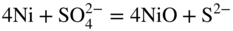
 decomposes as soon as it moves out into the Na2SO4. Consequently, a porous non‐protective nickel oxide scale is formed, and accelerated oxidation proceeds.
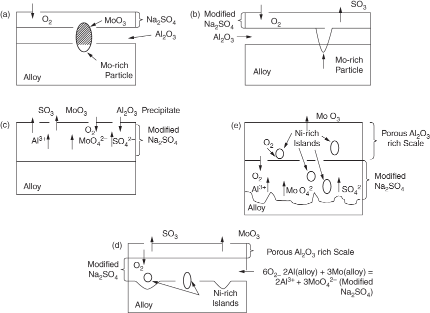
15.3.3 Effect of Sodium Chloride


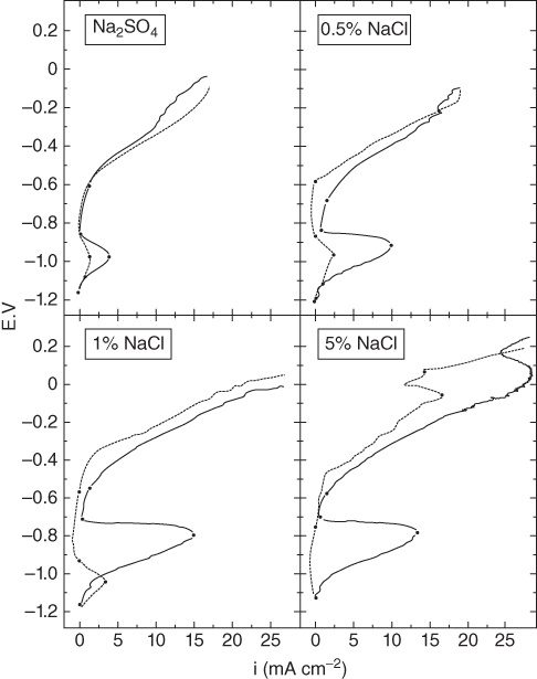

 alone. This was further evidenced by particular experiments that have been concerned with determining the inhibiting role of NaCl on Ni in the passive–transpassive area.


 subions, accompanied by the corrosion of the metal interacting with the dissolved oxygen and the chloride ions, as well as with the chlorine and oxide ions formed in the reaction of oxygen with chloride ions.
15.4 Mechanisms of Hot Corrosion

 (NiO + O2− →
  ) and at lower values as Ni2+ (NiO → Ni2+ + O2−). Logically, these two types of dissolution are termed as basic and acid dissolution, respectively. It should be noted that the hot corrosion process, especially with acidic fluxing mechanism, strongly depends on the temperature. As described earlier, if the temperature of exposure is lower than the melting point of the melt, the corrosion would not occur unless a complex mixture of salts is formed. In the case of Ni, a mixture of NiSO4 and Na2SO4 is formed, which, according to the phase diagram given in Figure 15.10, has a eutectic temperature of 671 °C. Thus, at temperatures lower than 884 °C, the melting point of Na2SO4, hot corrosion would result only when the eutectic mixture is formed.
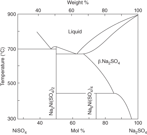
15.4.1 Acidic Fluxing
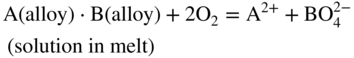
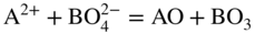
 participates with the S2, SO2, and SO3 species from the gas or dissociated melt in converting the alloy to corrosion products either by chemical thermodynamic reaction or electrochemically transported as an ion for a subsequent reaction with the gaseous medium. Thus, for an alloy AB,


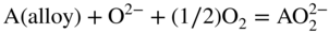
15.4.2 Basic Fluxing

15.5 Hot Corrosion of Gas Turbine Alloys
Technique
Advantages
Disadvantages/limitations
Burner rig test
Simulates gas composition, pressure, velocity, and temperature of gas turbine engines
Complex process and requires long running time. Difficult to control accurately all the parameters
Furnace test
Corrosion conditions can be controlled depending upon the requirements, i.e. severe or mild corrosion
Difficult to maintain salt deposition rate for longer times
Crucible test
Most simple and highly useful for preliminary screening of the materials and coatings
Corrosion is severe for alloys or coatings having low or intermediate resistance to hot corrosion
Thermogravimetric test
Precise weight gain measurement possible under different test conditions, i.e. gas composition, temperature, salt composition, etc.
Not useful for predicting the life of materials and coatings
Electrochemical test
Fast and useful for ranking the materials and coatings based on oxidation–reduction phenomenon
Yet to be fully established
15.6 Methods of Evaluating Hot Corrosion
Alloy
Al
Ti
Cr
Co
Ni
W
Ta
Re
Mo
Hf
Ir
Others
Nimonic 75
—
0.4
20
—
Bal
—
—
—
—
—
—
Fe, C
Nimonic 105
4.7
1.3
15
20
Bal
—
—
—
5.0
—
—
C
Inconel 100
5.5
5.0
10
15
Bal
—
—
—
3.0
—
—
Zr, C, B, V
Inconel 713
6.0
0.8
12.5
—
Bal
—
1.75
—
4.2
—
—
Zr, C, B, Nb
MAR M‐200
5.0
2.0
9.0
10
Bal
12.5
—
—
—
—
—
Zr, B, C, Nb, Fe
IN‐738
3.4
3.4
16
8.3
Bal
2.6
1.75
—
1.75
—
—
Cb, Fe, C
CMSX‐4
5.3
1.0
6.5
10.4
Bal
6.1
4.9
0.8
—
—
—
—
MAR M‐247
5.5
1.0
9.0
10.0
Bal
10.0
3.0
—
0.6
1.5
—
B, Zr, C
MAR M‐509
—
0.2
23.5
55
10
7
3.5
—
—
—
—
Zr, C
CM 247 LC
5.6
0.7
8.1
9.2
Ba
8.5
3.2
—
0.5
1.4
—
B, Zr, C
Inconel 718
—
—
18
—
Bal
—
—
—
3.0
—
—
Fe, Cb
CMSX‐10
5.7
0.2
2.0
3.0
Bal
5.0
8.0
6.0
0.4
0.03
—
—
TMS‐75
6.0
—
3.0
12.0
Bal
6.0
6.0
5.0
2.0
0.1
—
—
TMS‐80
5.8
—
2.9
11.6
Bal
5.8
5.8
4.9
1.9
0.1
3.0
—
15.7 Prevention of Corrosion
System
Coating
Relative lifetime
Land‐based aircraft
DS MAR M‐200 + Hf
Uncoated
≪0.5
Standard aluminide (PWA 73)
1.0
Rh–Al (BB)
<1.5
Gas‐phase aluminide (PWA 275)
<1.5
Modified aluminide (PWA 263)
1.5
Pt–Al (RT 22)
1.5
NiCoCrAlY overlay (PWA 271)
2.75
Marine aircraft
MAR M‐002
Standard aluminide
1
Pt–Al
2.5–3
CoCrAlY
2
Industrial
IN‐738
Uncoated
1
PtCrAl
>3
CoCrAlY (plasma sprayed)
>2
CoCrAlY (clad) plus Al diffusion coating
>6
FeCrAlY
2
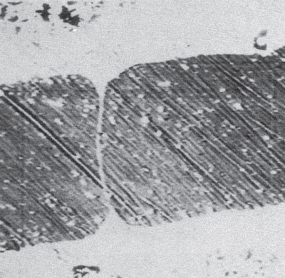
Marine
Rene 80
Standard aluminide
1
Rh–Al
1–2
CoCrAlHf
2
CoCrAlY
1
CoCrAlY+Pt/Hf
2
CoCrAlHfPt
2.3
15.8 Conclusions
15.9 Questions
References
Further Reading
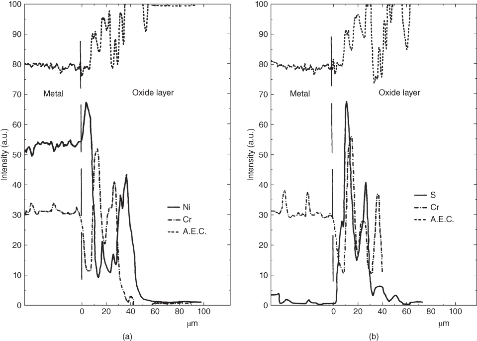
Hot Corrosion
15.1
15.2
15.3
15.4
15.5
15.6
15.7
15.8
15.9
15.10
15.11
15.12
15.13
15.14
15.15
15.16
15.17
15.18
15.19
15.20
15.21
15.22
15.23
15.24
15.25
15.26
15.27
15.28a15.28a
15.28b15.28b
15.29
15.30
15.31