Greg Zinter Greg Zinter Services Inc, Edmonton, Alberta, Canada There are two primary and complementary types of in-service pipeline inspection—internal and external. Internal inspection is conducted by a range of in-line inspection (ILI) tools and is discussed in Chapter 29. External inspection is conducted in the ditch on the outside surface of a pipe that has been excavated (which is the usual case, as most pipelines are buried) and exposed. In-the-ditch inspection begins with locating and safely digging up a pipeline in a known specific location. The criteria for selecting a location are usually based on the detection of a potentially dangerous anomaly in a pipeline by an ILI tool. This chapter discusses the application of nondestructive examination (NDE) techniques and technologies in the external inspection of in-service pipelines. Specifically, this chapter focuses on the following: NDE is a critical part of any pipeline integrity program. The term NDE is interchangeable with nondestructive testing (NDT). The American Society for Nondestructive Testing (ASNT) defines NDE as “the process of inspecting, testing, or evaluating materials, components, or differences in characteristics without destroying the serviceability of the part or the system.” For pipeline inspection, NDE uses an appropriate inspection technology to examine and assess a pipe and pipe anomalies without destroying it. Most commonly, this examination occurs when a pipeline is in service. In this chapter, NDE refers to a “direct” measurement technology that is conducted from the outside of the pipe. In this examination method, a technician physically examines a pipe with a variety of techniques that begin with a visual assessment. Direct measurement and evaluation provide the most accurate and reliable data. By comparison, ILI is an inferred measurement where a tool with a specific inspection technology, such as magnetism or ultrasonics, is inserted into a pipeline. This ILI tool travels down the pipeline and takes measurements that require some type of post-processing to provide useable data. Technically, ILI also fits the aforementioned definition of NDE. It is important to understand that the two reasons to conduct NDE on a pipeline are safety and verification of ILI data. Both of these reasons directly support the primary objective of a well-designed pipeline integrity program, which is to support the safe and economical operation of a pipeline over its entire life cycle. A pipeline is designed with a factor of safety to allow safe operation without ruptures or leaks. This factor of safety is an engineered value that is well-understood, and it provides a buffer between the operating pressure of a pipeline and the failure pressure of the pipe material. The results of NDE provide data that can be used to calculate the remaining strength of a pipeline in a location where a change in the material characteristics results in a change in the design pressure of a pipeline. This information can be used immediately to confirm the protection of the excavation and assessment crew working on the pipeline. A pipeline operator will lower the pressure of a pipeline to ensure that there is an appropriate factor of safety to protect the crew. A typical excavation pressure is the rupture pressure calculated from the information from the ILI inspection multiplied by a safety factor. If this value is greater than the maximum operating pressure, the operator will apply a safety factor to the highest actual operating pressure during a given period of time prior to the excavation. By verifying the size of the defect, this initial assessment will provide confirmation of a safe operating pressure. The larger safety perspective is to ensure the pipeline is safe to operate at the operating pressures. The NDE data will lead to an engineering calculation that will dictate the appropriate repair method. The repair might require the installation of a reinforcement sleeve to reestablish the design safety factor. Regardless of whether or not a sleeve is installed, the final steps in every assessment excavation include recoating and burying the pipe. NDE data are always compared with ILI data. This comparison verifies the stated accuracy of the tool, which either confirms the results of the ILI tool or identifies inaccuracies with the tool or data interpretation. Any inaccuracies might result in the immediate review and adjustment of the entire ILI data log, result in a complete reanalysis of the integrity of a pipeline, or lead to further development of the tool or the analysis to improve the ILI tool’s accuracy. Most anomalies that threaten the integrity of a pipeline are associated with a defect in the external pipeline coating. For this reason, some background understanding of pipe coatings is helpful. Regardless of the type of coating, the most common root causes of coating failures are as follows: For most large-diameter hydrocarbon pipelines, there are three primary types of coating. While these are different coating types, they are often confused with each other when they are first encountered on an integrity dig. In both cases, there is a polymer—either coal tar or asphalt—a fibrous binder, and some solvents to help the polymer flow onto the pipe during application. In some cases, an outer kraft paper wrapper may be used. Both types of coating are hot applied to the pipe. As the hot mixture cools and the solvents evaporate, the material hardens and forms a durable protective layer on the outside of the pipe. Historically, these coatings come with significant environmental and safety concerns due to the hazardous nature of the petroleum solvents and the asbestos, which was sometimes used as a binder and an insulator. They were most commonly used on large-diameter hydrocarbon pipelines until the late 1960s. Over time, these coatings dry out and become quite friable. They are very effective coatings as long as they are not disturbed. These coatings will also degrade rapidly when exposed to air. The exposed coatings that will not be removed as part of the inspection (i.e., at either end of the excavation) should be supported and protected to prevent further degradation. Some typical problems related to asphalt or coal tar epoxy coatings are as follows: Tape wrap coatings were a functional improvement over coal tar or asphalt-based coatings because they were less hazardous products and easier to apply in the field. The tape is usually a plastic film of polyvinyl chloride (PVC) or polyethylene (PE) with a self-adhesive backing. Once the pipe surface has been blasted and primed, the tape is spiral-wrapped on the pipe. It is common to use a layer of mastic to bond the tape to the pipe. The performance of the tape wrap coating is directly related to proper surface prep and application procedures. The tape can be hot- or cold-wrapped. Disbondment is a common issue, particularly with cold wrap-applied tape or when the operating temperature of a pipeline has increased significantly. This disbondment leads to two problems: first, the pipe is exposed to a corrosive environment and, second, the disbonded tape effectively shields the pipe from cathodic protection. Tape coatings replaced coal tar or asphalt enamel coatings and were most commonly used from the late 1960s to the middle 1970s. Some typical problems associated with tape wrap coatings are as follows: Fusion bonded epoxy (FBE) coatings have become the most popular coating systems on large-diameter hydrocarbon pipelines in North America. Electrically charged epoxy powder is sprayed onto the heated, grounded pipe joint. The powder melts and fuses with the steel. Because FBE is applied in a shop environment, quality control of the surface preparation and application process is easily managed. The result is a very durable and impermeable hard shell coating. There are variations on FBE where a multilayered coating is applied for greater protection and abrasion resistance. Typical problems encountered with FBE coatings include the following: There are other types of coatings such as extruded polythene jacket, yellow jacket (YJ), wax-based coatings, or fiberglass. An extra protective layer, such as “rock guard,” is used to wrap pipes where the soil is rocky. Concrete weights are also placed over pipelines in wet environments to counteract buoyancy. Technically, an anomaly is a deviation from the norm. For pipelines, it is an imperfection in the steel, such as a crack or an area of corrosion. Anomalies are also known as features, defects, or indications. Most anomalies represent a threat to pipeline integrity because they can grow and further compromise pipe strength during the operation of the pipeline. Much has been written about the type of pipeline anomalies and the way they are categorized. For the purposes of this discussion, the categories have been based on those described in https://pods.org/ [1]. It is common to encounter a complex pipeline anomaly or feature where two or more anomaly types exist in one location. Volumetric anomalies in the pipe wall are caused by a change in the volume of the material in the pipe wall compared with the adjacent nominal wall. The most common types of volumetric anomalies are as follows: As this is the most common reason for metal loss on pipelines, it is also one of the most common reasons for pipeline failures. External corrosion will occur when there is a break in the coating and the cathodic protection system is not able to prevent the electrochemical reaction between the electrolyte in the soil and the pipeline steel. Internal corrosion can be caused by microbial activity or erosion from particulates that are entrained in the fluid. Corrosion can be spread over a general area or be concentrated in a pit, or both conditions can exist. The biggest influence to the size of an external corrosion anomaly is the type of the coating and the size of the coating defect. Internal corrosion can be managed by regular pipeline cleaning and injected corrosion inhibitors. Figure 34.1 shows a typical deep external corrosion feature. Figure 34.1 Typical external corrosion feature. (With permission of Applus RTD.) These can occur during construction, either when the pipeline is first built—during subsequent excavations for inspection, maintenance, or modification—or when a third party is excavating the right-of-way. These anomalies occur because of a piece of equipment hitting the pipe. This is another very common cause of pipeline failure. Figure 34.2 shows a typical gouge in a dent. Figure 34.2 Gouge and dent. (With permission of Applus RTD.) These are defects that originate in the mill and can include general variation in wall thickness (either more or less than nominal), inclusions, mill slug, or trim marks from trimming the long seam. These anomalies are usually present during the original hydrotest and do not always grow with pipeline usage. As a result, volumetric anomalies represent less of a threat than corrosion, or scratches and gouges. This can include arc burns or puddle welds from poor girth weld practices, grind marks, or handling damage. These are also less of a threat to the integrity of the pipeline as they are usually present during the post-construction hydrotest. A planar anomaly “is formed by separation of previously continuous material. Planar anomalies are two dimensional and do not significantly change the total cross-sectional area of the pipe wall” [1]. The most critical anomalies in this category are those that break the surface of the pipe. The most common types of planar anomalies are as follows: Cracks, like corrosion, will grow in pipelines that are in service, unless they are found and repaired. Cracks form due to environmental conditions, such as stress corrosion cracking (SCC), elevated hydrogen concentrations, or manufacturing processes (hook cracks). Cracks are often found in association with corrosion or gouges. Given the complexity of detection and the consequences of an undetected feature, the industry relies on in-the-ditch assessment to continually improve ILI technology that is used to find cracks. Figure 34.3 shows an SCC colony. These can occur in the pipe body or on the pipe surface. Unlike cracks, laminations that are not surface-breaking do not normally grow with time. If a mid-wall lamination is found in an integrity assessment, it was probably present when the pipeline was constructed and pressure tested. Regardless, some operators choose to install sleeves for these defects to manage the pipeline risk. Geometric anomalies result from a change in the shape of the pipe. The most common cause in this category is mechanical damage. These anomalies include the following: These occur when an external object interacts with the pipe to cause a deformation. Dents are different from scratches and gouges, in that a dent is a larger deformation of the pipe wall. The most common cause is from excavation equipment or rocks in the bottom of the pipeline ditch. Dents often contain gouges or scratches. Figure 34.2 shows a gouge inside a large dent, which was probably caused by an excavator. This occurs due to excessive external stress on the pipeline that usually acts at right angles to the pipe surface. This stress might cause the pipe to deform into an oval-shaped cross-section or ovality. The design strength of a pipeline assumes the pipe is circular, and any change in this shape will change the ultimate design strength. Figure 34.3 SCC colony. (With permission of Applus RTD.) This is also caused by excessive external stresses. These stresses are usually aligned in the axial direction and are often caused by geotechnical movements on slopes or at river crossings. A buckle means that the pipe has yielded past its elastic limit and the original design strength is compromised. Any one of these anomaly types can compromise the design strength of a pipeline. It is common for a number of anomaly types to coexist in the same feature. For example, corrosion and cracking are often found together on some pipe types. This factor makes an assessment much more complex and more critical and increases the probability of a pipeline failure. A variety of measurement technologies are available for in-the-ditch pipeline integrity assessments. It is important to be prepared using the appropriate technology for the type of anomaly that will be assessed. Table 34.1 is a summary of these technologies, with a list of the most appropriate use. NDE measurement technologies are described in the following sections. Visual assessment is the first level of assessment and probably the most basic, yet it is perhaps the most critical. A technician: Table 34.1 Overview of NDE Inspection Techniques The pipeline operator is responsible to provide inspection criteria. A typical assessment criterion requires the identification of all surface anomalies deeper than 10% of actual wall thickness and the assessment of all anomalies >20% of the actual pipe wall thickness. Tools required for this assessment include a: External metal loss can be effectively mapped using a grid and measuring the minimum pipe wall thickness in each square. To make the grid, a chicken wire of the specified grid size (usually 12.5 mm [0.5 in.] square) is placed over the area to be measured, and white paint is sprayed over the grid and onto the pipe. A manual pit gauge is used to measure the maximum pit depth in each square of the grid, or an ultrasonic pen probe is used to measure the minimum wall thickness in each grid square. These measurements are recorded and used to calculate the remaining strength of the pipeline. External metal loss features can also be mapped by surface profilometry systems, such as lasers. Figure 34.4 illustrates a typical manual grid. Magnetic particle inspection (MPI) is conducted by applying an aqueous mixture that contains iron particles onto a pipe that has been painted white, while an electromagnetic yoke is placed on the pipe and energized. The magnetic energy generates visible lines of magnetic flux between the legs of the yoke. Any surface discontinuity, such as a surface-breaking crack, shows as a disturbance in the visible lines of magnetic flux. This technology is very effective in detecting stress corrosion cracking. Figure 34.5 illustrates the use of a magnetic yoke on a pipe coupon that has been painted white and sprayed with iron particles in an aqueous solution. When a transducer is placed on a pipe, ultrasonic sound energy is projected into the pipe wall. This energy reflects off internal features and back to the transducer. A technician interprets the ultrasonic reflection that is displayed on a screen. This method is used to identify potentially dangerous internal or subsurface anomalies, such as cracks and cracklike features, delaminations, and geometric features, such as the internal diameter pipe wall and welds. Some ultrasonic inspection (UT) technologies are also used to size surface-breaking cracks. Figure 34.6 illustrates a typical UT set being used for pipe assessment. Figure 34.4 Typical grid over a corrosion feature. (With permission of Applus RTD.) The common types of UT technologies used in pipeline integrity assessment include the following: Figure 34.5 Magnetic yoke in use on a pipe coupon. (With permission of Applus RTD.) Figure 34.6 Typical ultrasonic device in use on a pipe. (With permission of Applus RTD.) All UT methods require a clean pipe surface and a viscous couplant between the transducer and the pipe wall to conduct the sound energy into and back out of the steel. These transducers are handheld probes, or they are mounted on an automated traveler, which takes a systematic path over the pipe. The profile of an external pipe wall is measured by an instrument that projects laser light onto the surface of the pipe. This light is reflected back to the device, which measures the travel time of the light to measure the distance between the sensor and the pipe surface. This process occurs at a specific time, or spacing, and provides a three-dimensional surface profile of the external pipe wall and the anomaly of interest. The sensor is handheld or mounted on an automated traveler, which moves in a specific grid pattern. The data are recorded in a digital file, which results in two benefits—data entry errors are eliminated and the digital file is suitable to calculate the remaining pipe strength. Laser profilometry is: The excavation package is the first step in the in-the-ditch inspection. It is generated by the operator and provided to the NDE crew. It is a concise set of information that includes the following: Metadata, which at a minimum, include: The location and the dimension of the anomalies on the pipe will be reported in a systematic convention of measurement. The most common convention measures the position relative to an upstream girth weld and the top, or 12 o’clock, position of the pipe. These are also the normal reference points for ILI data. The same convention is used to record the data collected by the in-the-ditch assessment. A listing of the source data to compare to the in-the-ditch results usually consists of the pertinent portion of an ILI log that describes the location and the dimensions of the anomalies of interest. Figure 34.7 is an example of a pipe drawing with a single anomaly of interest from an excavation package. There are three data sets related to in-the-ditch assessment. The first set is collected from the results of an assessment of the ambient pipe condition. This includes data from soil and water sampling, microbiologically influenced corrosion or pH testing, and the measurement of the pipe to soil potentials. Data collection and analysis are discussed in Chapters 49, 55, and 66. The second data set describes the coating type and condition. A failure of the coating can lead to the formation of external pipe wall anomalies. An assessment of the coating will provide a measure of the health of the coating as well as the effectiveness of the cathodic protection system. Consequently, the type and condition of the coating are critical data that are important to the assessment, and it should be carefully noted. Areas of coating damage should be clearly labeled and photographed for inclusion in the final report. Coating samples or samples of deposits in the area of coating failures might also be collected as part of the assessment. Typical coating data collected during an in-the-ditch integrity assessment include the following: The third data set, and the primary focus of this chapter, is the NDE data collected in the assessment of the condition of the pipe. These data include the size of the anomaly, which is described by the width, length, and maximum depth. Depending on the anomaly and the type of dig, more detailed sizing information might be required. There are various ways to collect these data. Depending on the type of anomaly, different technologies, such as laser profilometry, MPI, or UT, are used to assess the anomalies and provide data. Laser profilometry and UT tools can be automated to speed the measurement and data acquisition and improve data resolution and quality. While these automated tools have been a boon to in-the-ditch assessment by speeding the data gathering and providing more accurate data, a good assessment will always rely on good field notes and a good photographic record. Some tablet-based data collection tools are available, but currently, most technicians rely on written field notes to ensure their reports are concise and complete. Technicians are advised to use an NDE data collection form that the operator has approved to encourage consistent and complete data collection. Pipeline integrity is perhaps the most stimulating and challenging of all NDE work. It requires a technician to look beyond the bounds of the scope of work to ensure there are no unexamined significant threats to a pipeline, and it requires the organization of a relatively complex data set into a concise final report. Figure 34.7 Drawing from a typical excavation package. (Reproduced with permission of Applus RTD.) This work requires two sets of procedures. They are a standard set of procedures for a specific type of NDE (e.g., MPI or UT) and a set of procedures to put these technologies to work in the context of pipeline integrity. This second set of procedures should include such things as specific criteria for anomaly assessment, data collection, photographic methods, and reporting. The purpose of the entire set of procedures is to provide a concise list of steps for in-the-ditch inspections that result in a safe, accurate, and repeatable outcome. The second set of pipeline integrity specific procedures is developed from the following sequence of events and tasks for conducting in-the-ditch inspection. First is the preparation for the excavation: Figure 34.8 Typical pipeline excavation. (With permission of Applus RTD.) It is best to cross-reference as many data sets as possible to ensure the excavation is in the correct location. Figure 34.8 shows a typical pipeline integrity excavation. It is important to understand the measurement convention when marking and measuring the integrity anomalies. Most conventions reference the upstream girth weld and the top dead center of the pipe looking downstream. This convention is usually provided by the operator. This is the baseline for the NDE crew to begin to evaluate these anomalies. External metal loss features, such as external corrosion or gouges, are assessed with a manual grid and pit gauge, UT pen probes, laser profilometry tools, or a combination of the three. Cracks and crack fields are assessed using a combination of techniques. If the operator is interested in quantifying the cracks, the following is the most common approach: Operators who are not interested in correlating crack depths to ILI data might choose to simply install a reinforcement sleeve on the pipe over the cracks. Good NDE data management begins long before an NDE technician enters the ditch. A pipeline integrity management plan is incomplete without a solid plan for the acquisition, organization, and analysis of the NDE data set. The requirement for the NDE data set should be reflected in the pipeline integrity excavation package, which is the primary source of direction for the technician. NDE data are used in the calculation of the remaining strength of a pipeline. An error in the data will result in an incorrect calculation, which will lead to either an unsafe pipeline condition or a waste of resources. Automated measurement and data collection improve the accuracy of measurement and virtually eliminate errors in data collection. All the processes and procedures, from the initial assessment to final reporting, must be built on the principles of robust quality control and assurance. The report is the final result of the assessment, and it is critical that the report is concise and complete. An unclear report will cause confusion or even incorrect analysis. It is also critical to ensure the report and associated data are labeled according to a coherent naming convention and stored in a secure, searchable location. A missing or lost assessment report leaves no record or evidence that the assessment ever happened. A good and complete report begins with a clear definition of the objectives of the dig and includes a clear set of reporting instructions. A typical reporting procedure should specify: What is next for in-the-ditch pipeline anomaly assessment? The world of pipelines and pipeline integrity has become significantly more demanding in the last 5 years. It is more important than ever to continue to improve existing technologies and develop new ones. Most of the recent advancements have been evolutionary rather than revolutionary. For example, the primary technologies have not changed, while, in some cases, the resolution and accuracy have improved. These advances in data improvement have been made possible by the ongoing miniaturization and efficiency of digital technology. These developments have allowed the digitization and automation of more parts of the assessment process. This technology advancement has led to better analysis and a higher degree of confidence due to quicker results, higher resolution, and more accurate data. The electromagnetic acoustic transducer (EMAT) was developed because of the need for a reliable crack detection device that can be used in a dry gas environment. Whereas most of this development has focused on ILI technology, it remains to be seen if can be applied to external, direct measurement. The commercialization and development of the EMAT ILI into a reliable inspection tool is directly related to exhaustive verification of the tool results by in-the-ditch NDE assessment. Quite literally, structured-light technology is a high-resolution digital camera that takes a photograph of a prepared pipe and uses the shades of the image to model the surface profile of the pipe. In principle, the result is similar to a laser profilometry device. The data output is suitable for use in an automated program that calculates the remaining strength of the pipe wall. This technology is most effective for describing surface metal loss and pipe deformation defects. Faster processing and smaller transducers have allowed advancements in the analysis of the UT data. This advancement has led to the real-time, three-dimensional projection of the UT signal so that internal pipe features are more accurately displayed. This technology has the potential to make the interpretation of ultrasonic signals less dependent on the skill of the operator. Recent developments in eddy current technology show some promise in the detection and quantification of cracks. The current state of the art in eddy current sensors shows an increase in data accuracy and repeatability. Some pipeline companies are in the process of validating eddy current technology to use to help detect and evaluate SCC colonies. This chapter has presented an overview of in-the-ditch pipeline assessment, including the objectives required for the proper design of the program, the role of ILI, available NDE inspection technologies, the type of data to gather, and the steps to create a good report. In-the-ditch pipeline inspection is a key part of any pipeline integrity program. It helps support the safe operation of a hydrocarbon pipeline and, if properly planned and conducted, it maximizes the overall lifecycle investment by the pipeline operator.
34
In-The-Ditch Pipeline Inspection
34.1 Overview
34.2 Introduction to Nondestructive Examination of Pipelines
34.3 NDE and a Pipeline Integrity Program
34.3.1 Safety
34.3.2 Verification and Advancement of Technology
34.4 Pipeline Coatings
34.4.1 Asphalt or Coal Tar Enamel
34.4.2 Tape Wrap
34.4.3 Fusion Bonded Epoxy
34.5 Types of Anomalies
34.5.1 Introduction
34.5.2 Volumetric
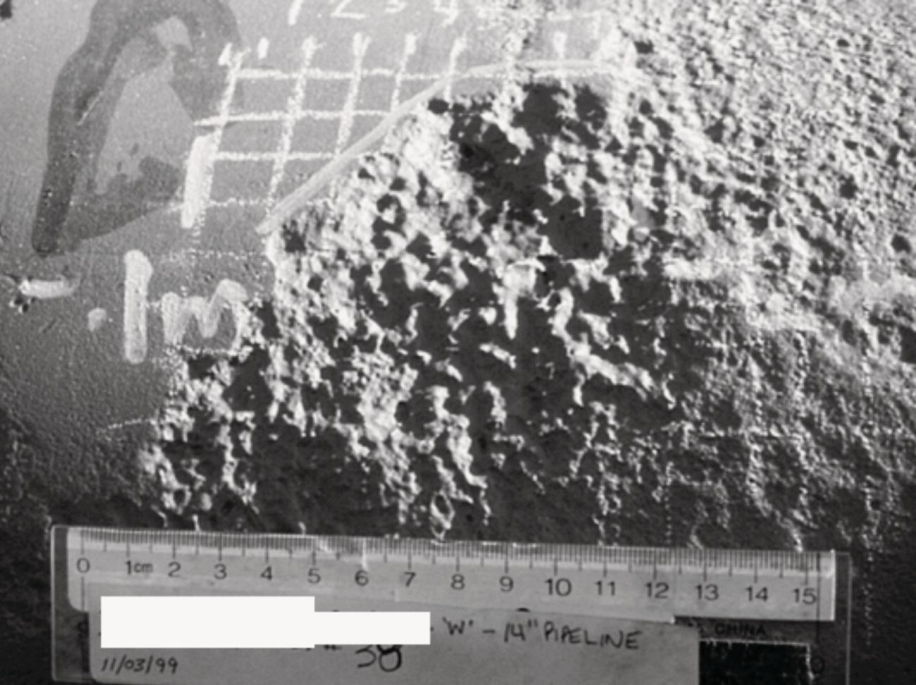
34.5.2.1 Corrosion
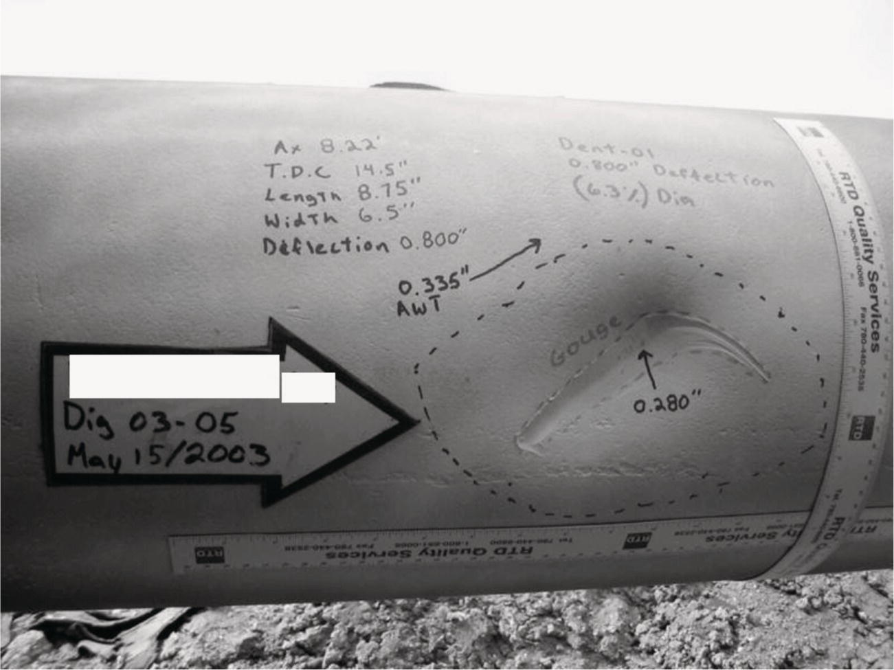
34.5.2.2 Scratches and Gouges
34.5.2.3 Manufacturing-Related Volumetric Anomalies
34.5.2.4 Construction-Related Volumetric Anomalies
34.5.3 Planar
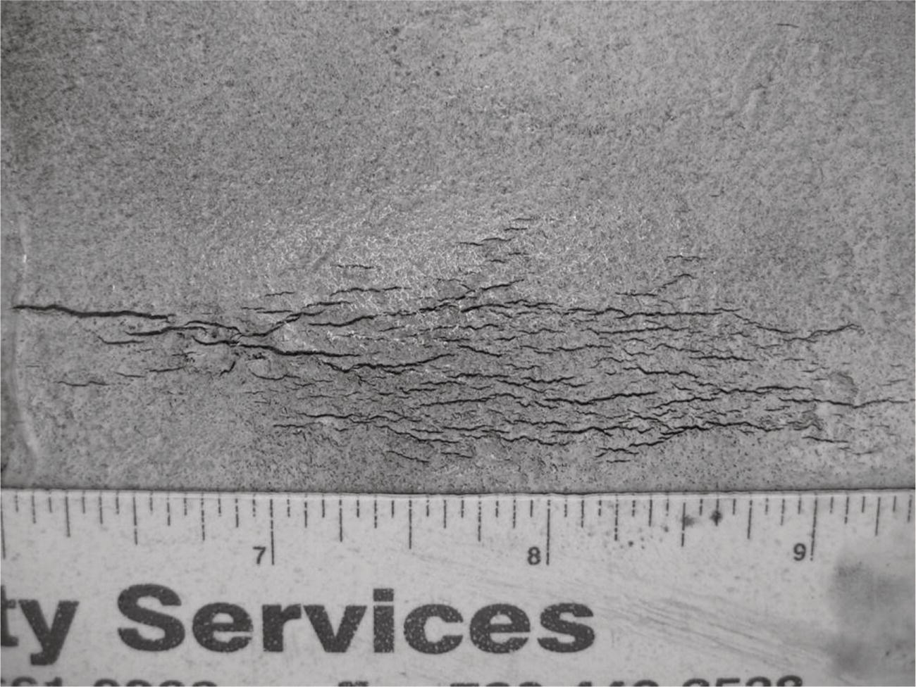
34.5.3.1 Cracks
34.5.3.2 Laminations
34.5.4 Geometric
34.5.4.1 Dents
34.5.4.2 Ovality
34.5.4.3 Buckle
34.6 NDE Measurement Technologies
34.6.1 Visual Assessment
Method
Typical Feature
Advantages
Limitations
Visual and physical measurement
Magnetic particle inspection
Ultrasonics:
Laser profilometry:
34.6.2 Manual Measurement
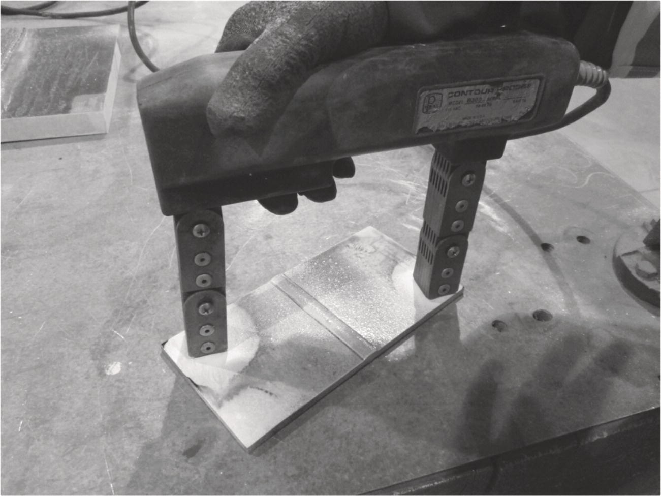
34.6.3 Magnetic Particle Inspection
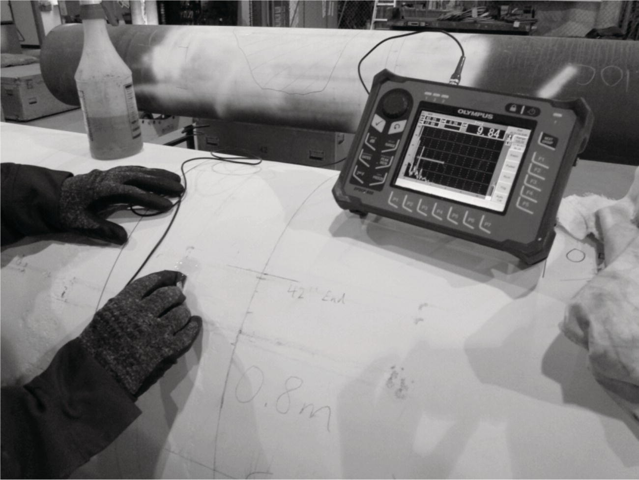
34.6.4 Ultrasonic Inspection
34.6.5 Laser Profilometry
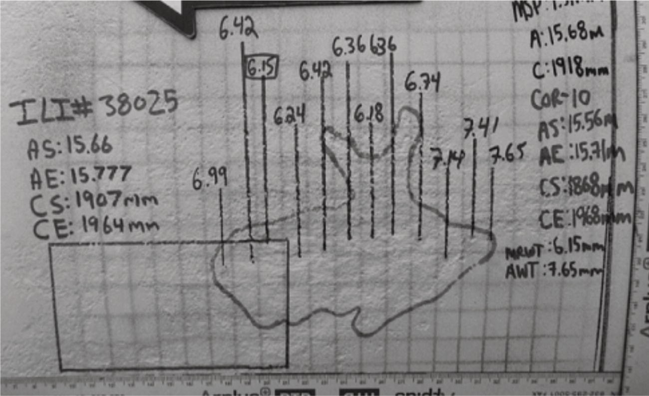
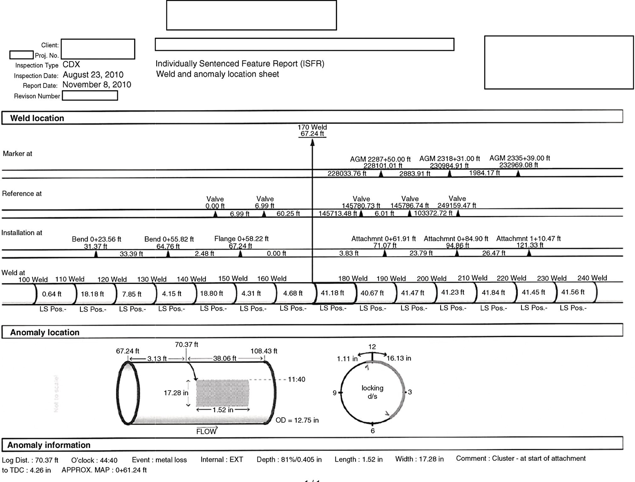
34.7 Excavation Package
34.8 Data Collection
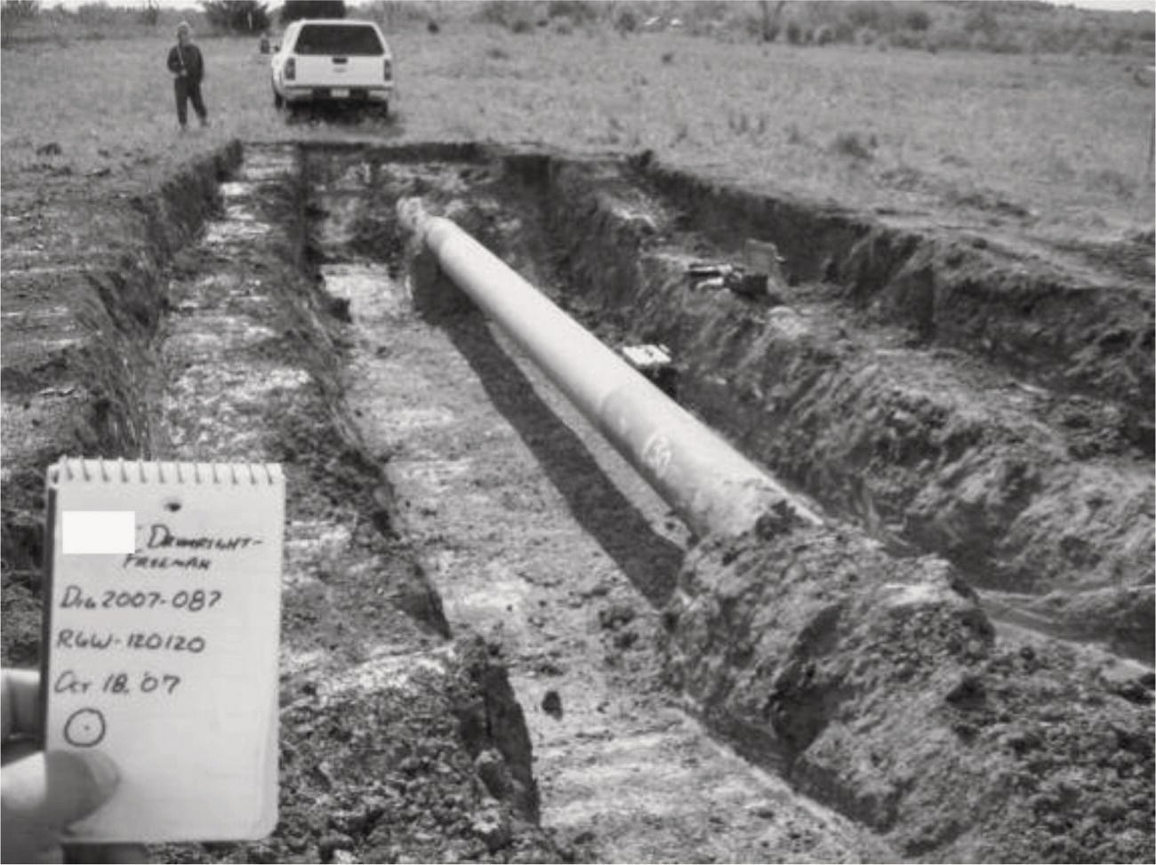
34.9 Conducting In-The-Ditch Assessment
34.10 Data Management
34.10.1 Quality Control
34.10.2 Reporting
34.11 Recent Technological Developments
34.11.1 Electromagnetic Acoustic Transducer
34.11.2 Structured Light
34.11.3 Ultrasonic
34.11.4 Eddy Current
34.12 Summary
Acknowledgments
Bibliography
Reference
Note