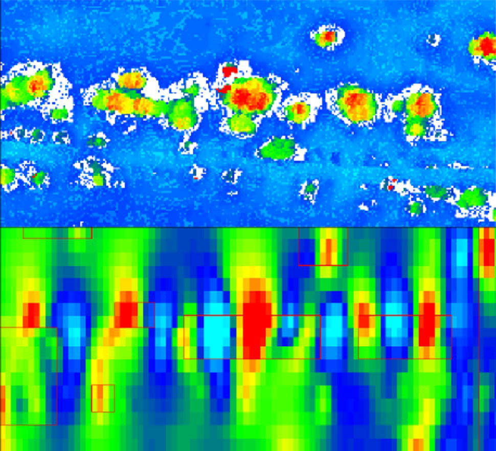
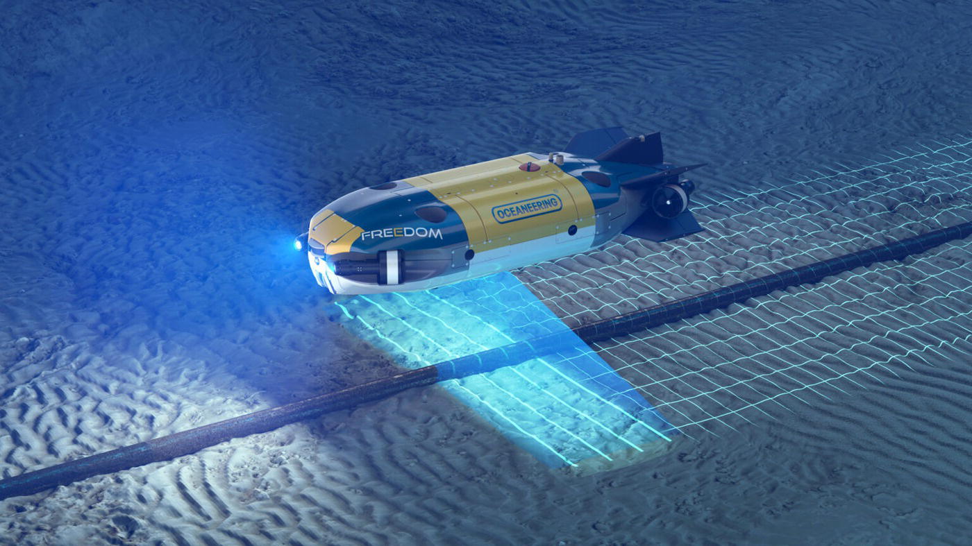
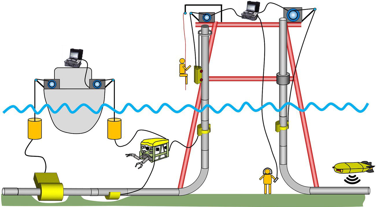
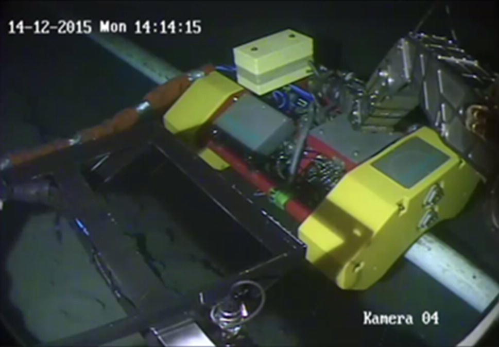
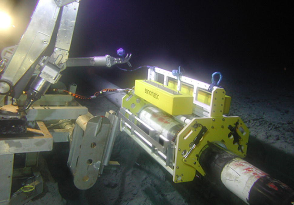
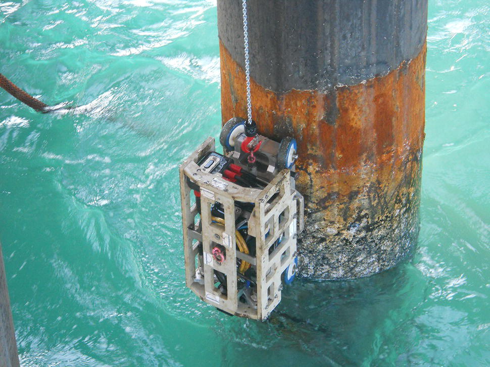
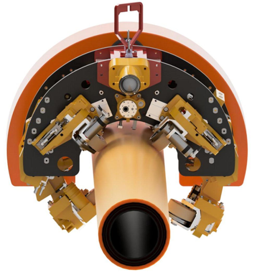
Konrad Reber Innetiqs GmbH, Stutensee, Germany The first pipelines were laid on soil, first on ground level and eventually below ground. Even though maintenance measures of these pipelines had to be developed, at least the pipelines were always accessible. Potential pollution issues of the environment became apparent quite quickly. Accessibility and the possibility to monitor lines are obviously key to integrity maintenance. With the advent of offshore oil production in the 1930 in the Gulf of Mexico and later in the North Sea and the Caspian Sea, pipelines laid on the seabed also became common. Since these lines were first constructed in shallow waters, maintenance intervention was usually done by divers. With the development of the offshore industry, the requirements for integrity also grew. After the 1970, pipelines were also laid in deeper waters, where access was no longer possible by divers. Pipelines started to fulfill different purposes as flowlines, injection lines, or export lines. Often export lines run from a platform to shore with a product that is treated such that internal corrosion threats are minimized. The diameter of export lines is generally larger ranging up to 48 in. This application is usually called a midstream service. Contrary to this, an upstream service is a pipeline operation closer to the well. Flowlines and gathering lines are generally smaller in diameter and often operate in a sour service regime and with a multiphase product. In such a case, corrosion threats and applied materials are very different from midstream lines, posing a different challenge to the inspection task. There are also some threats to offshore pipelines that are unknown to onshore lines. Anchors dropping onto a pipeline and pipelines dragged by anchors or trawl nets are commonly known problems [1]. The immediate consequence of a pipeline failure might be considered minor for an offshore pipeline compared to onshore pipelines. High consequence areas (HCA) are defined by population density in the vicinity of the line. Nevertheless, offshore oil spill environmental disasters are well known to the public, and reputation is quickly lost. In addition, the risk for offshore personal must always be considered because of the constraints of safe offshore work. Regular in-line inspections (ILIs) are also possible for offshore pipelines. In particular, long export pipelines are designed and constructed in a piggable manner. These lines often run over a considerable distance. They either run from platform to shore or from shore to shore. For the routing of the latter type of pipeline, political reasons are often more important than technical considerations. Because of the length, some technical aspects need to be considered. For onshore pipelines, an inspection length of 200–300 km from pig launch to pig trap is a rather long distance. Pumps or compressor stations and pig traps are located along the pipeline. For long distance onshore pipelines, a complete inspection would thus often be done in sections. This is not possible for longer offshore lines. The inspection needs to be carried out in a single run. The length is often over 500 km, the Franpipe for instance runs over a distance of 840 km and the Nordstream 1 runs over a distance of 1222 km. In both cases, there is no service platform in between. ILI tools are available that can do such inspections in one go. However, compared to the variety of technologies and vendors, the choice is limited. Many vendors do not serve the offshore market, where special requirements for safety and tool availability exist. Also, the more recent inspection technologies are often more power hungry as compared to standard methods. The inspection of 800 km typically requires a time span of 4–5 days of uninterrupted inspection data acquisition. The required power has to be carried along in batteries. Tools become longer to house more batteries. This again conflicts with the scarcity of space on offshore platforms. So far, all attempts to generate power by the tool’s motion have not been successful. One workaround for this problem has been, that an ILI tool runs in a type of “sleep mode” for a section and switches itself on, once a certain position is reached. This allows for the inspection of sections, while the tool physically runs the full distance. Nevertheless, ILI inspections have been done successfully over such a long distance [2, 3]. Contrary to onshore ILI operations, a later verification of the inspection results is difficult to perform. The effort is considerably higher and in practice one refrains from doing a lot of verifications. Nevertheless, a verification is possible using the tools and methods to be introduced in Section 30.3. Figure 30.1 shows internal corrosion in a subsea pipeline found with an ILI tool (lower image) and by corrosion mapping with an external device (upper image) [4]. With regards to internal inspection, there is also a variety of devices that run with an umbilical connection or tether to a control unit at the launching site [5]. Self-propelled tools often named crawlers are also available. These tools are applied, if the length of pipeline to be inspected is shorter. A typical application is the inspection of a riser (see Section 30.4). Figure 30.1 Verification of ILI findings on a subsea pipeline: AUT above, MFL below. (Reproduced with permission from Sonomatic [above] and Baker Hughes [below].) Compared to onshore pipelines, the access to offshore pipelines is different. While in-the-ditch work on onshore pipelines is often more an administrative challenge (right-of-way, permissions for excavation, etc.), the access to offshore pipelines is rather of a technical task. A riser is often easily accessible from the platform, except for parts under clamps and guides. The pipe on the seabed can only be accessed with submarine technology. Sometimes subsea pipelines are protected with rocks dumped onto them. This protects pipelines mainly from trawl nets and stabilizes them in general. In some cases, also concrete mattresses are used. Whenever possible, pipelines are laid flat onto the seabed and are hence in principle accessible. Seabed intervention, in particular dredging maybe required to get to the 6 o’clock position of the pipeline. In the early days of shallow water subsea pipelines, it was common to manually inspect them like onshore pipelines. A diver would take marinized handheld probes and spot-check areas under concern. With the need to avoid diver deployment, the construction of deeper water pipelines and the need to inspect longer sections the trend is now toward remote, automized, and even autonomous inspection methods. Naturally ROVs are used to deploy the instrumentation for inspection. Inspection class ROVs (remotely operated vehicles) carry out GVI (general visual inspection) and CVI (close visual inspection) [6]. With work class ROVs, heavier equipment can be employed that uses standard methods of nondestructive testing like ultrasonic technology (UT) or electromagnetic methods like eddy current technology (ECT). In general, three different degrees of interaction with the pipe can be distinguished and can be described as follows. In some cases, an ROV approaches the pipelines and stays close to it. It hovers above the line or runs along the line. More remote measurements like visual inspection are carried out. This is also typical for underwater cathodic protection (CP) surveys. An inspection can also be done with autonomous underwater vehicles (AUV). An example of such a tool is shown in Figure 30.2. Recently other methods of inspection have been added; e.g., free span detection. The second level of interaction is a configuration where an ROV deploys an inspection device onto the pipeline. This device holds on to the pipe with either magnetic attraction or a clamp. The device runs along the pipeline with its own drives like a crawler and is connected to the ROV via an umbilical. With the ROV being connected to its supply boat, control and data acquisition can be done from top side. Figure 30.2 The Freedom™ AUV by Oceaneering is an autonomous underwater vehicle to carry out various inspections on subsea pipelines on the seabed. (With permission of Oceaneering International Inc.) The highest level of interaction consists of a scan frame mounted onto the pipe. The device will also clamp onto the pipe but will be stationary. Sensing devices are mounted into the frame and inspection is carried out by scanning a sensor over a predefined area. To obtain data from a different area, the ROV displaces the scan frame. Obviously, the higher the degree of interaction, the more accurate data can be obtained, but the smaller is the area inspected. Hence, it very much depends on the scope of the inspection, which method is most suitable. The different methods of approaching the pipeline are shown in Figure 30.3. The preparation for the inspection depends on the method of inspection. Other than the already mentioned dredging, some measures of cleaning may be required. Subsea pipelines are affected by marine growth. The type and degree of marine growth depend on the climate zone and the water depth. Most marine growth is found in the splash zone and in shallow waters, which is still reached by sunlight. Typical marine growth consists of algae, sea anemones, and barnacles. Marine growth needs to be removed because it can impede the smooth scanning of a pipe surface. For very sensitive methods, like UT corrosion mapping, it may also need to be removed to allow for a reasonable inspection data quality. The typical cleaning methods are water jetting, scraping, and brushing. Often the cleaning devices are attached to the pipe in a similar way as the inspection instruments. Whether the coating needs to be removed depends on the coating type and the NDT method applied. For actual inspection devices, there is quite a variety of combinations of inspection and deployment methods [7]. Usually, a specific tool is offered by a specific vendor for a specific purpose. Hence, it is only possible to mention a few examples. Contrary to ILI inspection, the industry has not yet defined standard methods, which are codified and are offered by several service companies. Nevertheless, efforts have been put into verifying the effectiveness of the instrumentation with third-party verification and joint industry projects [8]. Figure 30.3 Methods of deployment of external inspection instruments. Figure 30.4 shows the “MEC-Combi Crawler™” by Innospection. The image shows the device being put onto the pipeline with an ROV. Once attached, the ROV will then retract and the crawler will move on the pipeline axially and also circumferentially allowing it to reach the 6 o’clock position. As an example, for a scan frame device employing a UT corrosion mapping, Figure 30.5 shows the tool “ROV-iT™” from Sonomatic. The upper image in Figure 30.1 was obtained with such a device. The ROV attaches the tool to a pipe, and a UT sensor takes a high-resolution mapping of the wall thickness from this spot. To get the readings from a different position, the frame is then repositioned. Another solution is shown in Figure 30.6. The device is called “Discovery CT™” and offered by Tracerco [9]. It uses computed tomography. Computed tomography, the same technology known from medical applications, allows for obtaining a high-resolution image of a cross section of the pipe. The technology is currently the only technique that allows for the inspection of a pipe-in-pipe configuration. The proper selection of the inspection position is required. This may be achieved by one of the mentioned faster screening type methods. As mentioned already, directly comparing the presented methods is difficult. They dramatically differ with respect to speed and accuracy. So, any increase in speed comes at the expense of lower resolution, and it is rather the scope of the inspection that will determine the method of choice. Figure 30.4 MEC-Combi Crawler™ by Innospection being put onto a dredged pipeline. (With permission of Innospection.) Figure 30.5 The ROV-iT™ tool by Sonomatic carrying out a corrosion mapping on a subsea pipeline. (With permission of Sonomatic.) Figure 30.6 The Discovery CT™ tool by Tracerco being attached to a pipeline for inspection. (With permission of Tracerco.) The riser, as an integral part of an offshore pipeline, is yet different under inspection and integrity aspects. The integrity and hence the inspection of a riser is especially important for a variety of reasons. The riser is close to the platform. Any accident thus immediately threatens the well-being of the crew. There are some threats that are typical to the riser. Any object floating on the water would impact the pipeline exactly in the splash zone. Hence, the riser is an especially vulnerable part of the pipeline. In an ILI operation, the tool also runs through the riser, and it is in principle inspected as well. However, it is often difficult to control the proper speed of the ILI tool because of the gravitational acceleration. The tool speed may be too fast for proper data quality. This is less of a concern in liquid lines. For gas or multiphase lines, however, this is a known problem. Pipeline risers also have a much higher wall thickness, which may put them outside of the ILI tool specification. The inspection may need to be complemented by an internal inspection using an umbilical tool or a crawler or by an external inspection. Finally, the riser is often protected by special materials. Monel cladding is common for corrosion and impact protection. Also, thick coating layers of Neoprene are common. For external inspection, any such unusual material composition may pose a challenge to the inspection. The splash zone part of the riser is often easily inspected from top side. An inspection device is hung from the top and lowered down along the riser pipe. It is either clamped to the pipe or attached by magnets. The attachment can be done by rope access technicians. The tool can then travel into the water, if it is properly marinized. Riser clamps and guides may obstruct the path that a device may travel along the pipe. Figure 30.7 shows an inspection device by Innospection performing an external inspection (here a conductor, riser would be the same configuration) in the splash zone using a magnetic eddy current technology. Figure 30.7 An inspection in the splash zone with the MEC MPS200+ by Innospection. (With permission of Innospection.) A special type of riser with respect to inspection is the flexible riser. This pipe type is used, among other applications, to connect floating productions systems to subsea wells and flowlines. The flexibility is achieved by producing this pipe type of several different layers of different thickness and materials [10]. Typical layer design would comprise a stainless steel carcass, polyethylene layers, and layers of carbon steel wires. These wires take the stresses of the pipe. Two layers of helically wound tensile armor wires take the axial loads, while a layer of an interlocked wire takes the hoop stress. Failure modes and integrity considerations are considerably different compared to rigid steel pipe. The carbon steel components that take the stresses of the pipe are placed in an annulus between two polymer sheaths, forming a volume tightened from the inside and outside. This annulus is surveyed by annulus testing [11]. Annulus testing allows for the detection of water or medium ingress possibly leading to corrosion of the carbon steel components. It is an integral testing, where a complete riser is tested from a vent at top side. By observing the response to suction and pressurizing the annulus, the tightness and the approximate location of a breach of the outer sheath could be detected. Annulus testing is a rather indirect measurement of the integrity of the load-carrying components, comparable to CP testing: If a protective system fails, the component could eventually fail as well. More direct NDT methods are also applied to flexible risers. Systems have been devised that carry out an annulus condition inspection on a local spot along the riser. This may be required if the riser pipe is too long or is not continuous, which is typical for deep-water installations. A UT sensor measures the response of a pulse sent into the layer structure from the outside. The response will depend on the medium found in the annulus. Several methods of evaluating the physical interaction of the UT pulse with the layers are used, including measuring the backwall echo from the outer sheath, the polarity of the backwall echo, and the reverberating backwall echoes of the steel wires, as well as other methods [12, 13]. The deployment is done with the same technologies described in Section 30.3.1. A crawler system by Innetiqs, that is used for flooded annulus detection, is shown in Figure 30.8. Figure 30.8 FADS tool by Innetiqs to inspect for annulus flooding on a flexible riser. (With permission of Innetiqs.) In a different approach, an electromagnetic method is used to measure the stresses found in the axially running tensile armor wires. The method is called MAPS™ [14]. If a single armor wire fails because of corrosion or cracking, the load will be released and taken up from the neighboring wires. The change in tensile stresses in steel can be measured by a change of the magnetization loop. This method is also suitable for a monitoring application. For an inspection more comparable to the internal scanning of a complete surface, external scanning methods using magnetically biased eddy current are used. MEC-FIT™ and MagControl™ FR are services offered. Because eddy current testing allows for testing through thicker sheaths of polymers, such sensors are used to scan the surface from the outside to detect corrosion or cracking on the tensile armor layers. An internal method would fail in this case, because of the presence of the carcass and pressure sheath layer. The internal inspection of the carcass is of course possible via the typical ILI tools [15]. The inspection and integrity maintenance of offshore pipelines require a different approach than for onshore pipelines. The threats, the operational possibilities, and the available tools differ considerably from the onshore environment, where solutions have been matured already over decades. This is especially the case for external inspection methods, which are difficult to compare to in-the-ditch methods. Hence, the current solutions are quite innovative, and the industry is transforming rather rapidly. It is prudent for every integrity engineer in this field to observe the most recent developments to assure that the best solutions are applied.
30
Inspection of Offshore Pipelines
30.1 The Inspection Challenge in Offshore Pipelines
30.2 Internal Inspection of Offshore Pipelines
30.3 External Inspection Methods for Subsea Pipelines
30.3.1 Deployment of External Inspection Tool
30.3.2 Examples of External Inspection Devices

30.4 Inspection of Risers
30.5 Conclusions
References