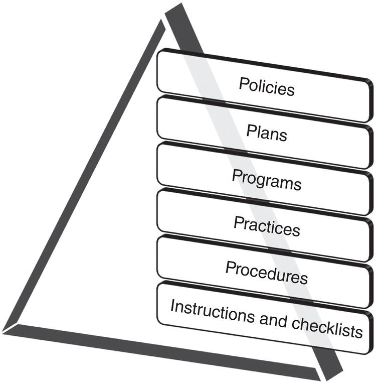
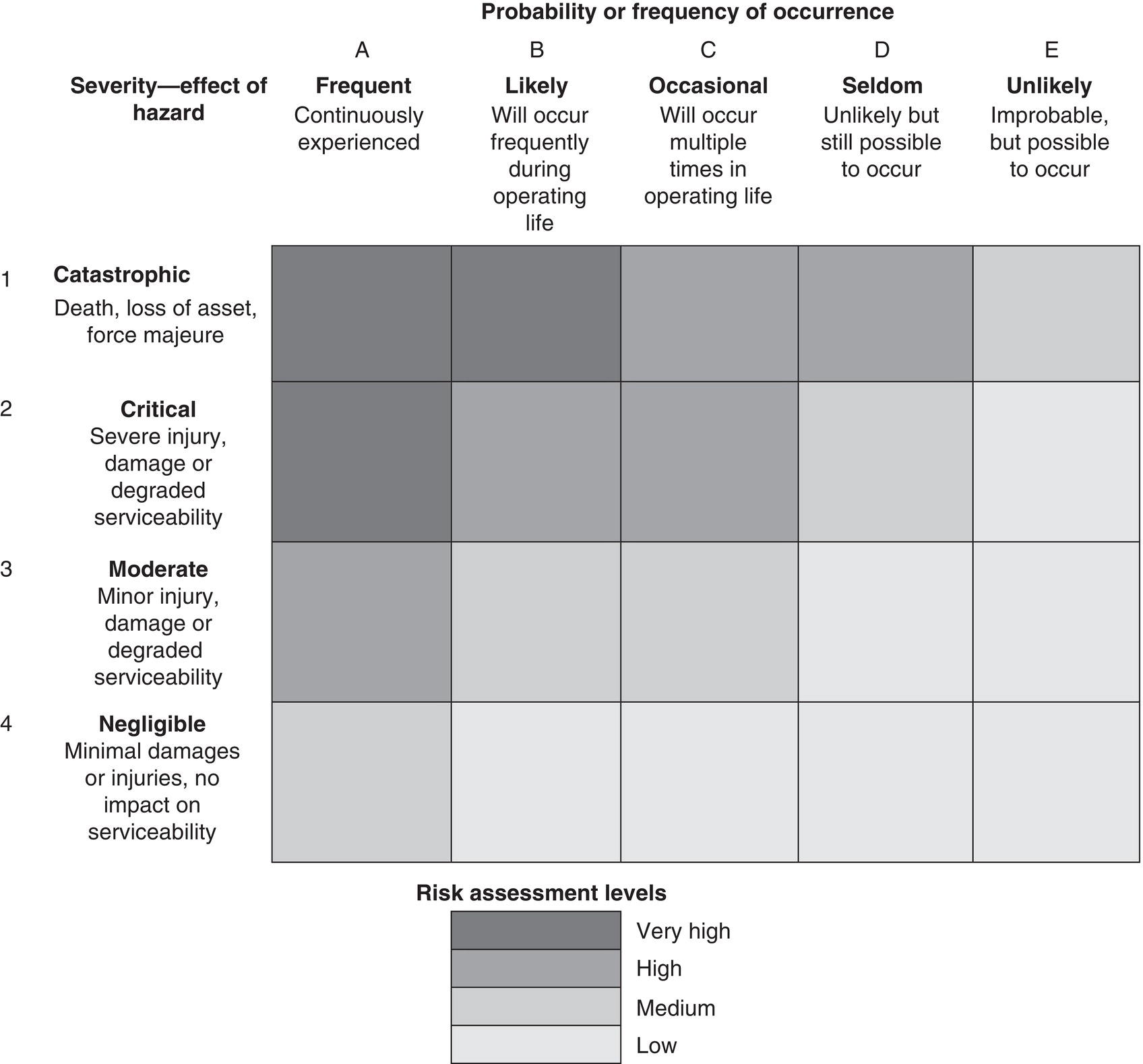
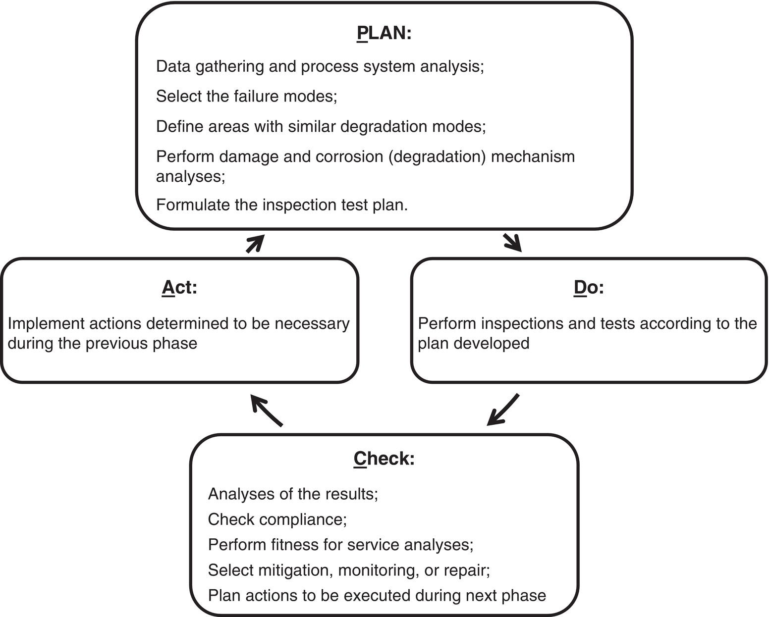
Greg Szuch1,* Mike Reed2 and Keith Leewis3 1Calgary, Alberta, Canada 2Consultant, Port Alberni, British Columbia, Canada 3Leewis and Associates Inc., Bragg Creek, Alberta, Canada Operators of oil and gas pipeline systems, like any other industrial/commercial enterprise, invest heavily in the creation of the physical assets that make up their businesses. Incumbent with the initial capital investment is the need for continued expenditures to maintain those assets such that they remain fit for purpose. Investing in integrity management is not only an obligation of operators but also a sound business decision. The process minimizes business risks associated with accidents and loss of production. With sufficient resources and ongoing application, the process is taking steps to meet public expectations, fulfills regulatory requirements, maintains shareholder values, and maximizes investor returns. However, the industry operators do not exercise sole discretion in these activities. Consensus standards by several Standards Development Organizations (SDOs) provide guidance to operators. In addition, government oversight through regulations can be found in jurisdictions wherever pipeline systems operate. Recent decades have unfortunately seen repeated industry failures which, in some cases, have resulted in significant loss of life and environmental and property damage [1–4]. Such tragic events resulted in the implementation of extensive minimum regulatory requirements for the management of the integrity of pipeline system assets. In many circles, these have come to be known as Pipeline—Integrity Management Plans (P-IMPs) and Facility—Integrity Management Plans (F-IMPs). With each incident, public demands to stop such incidents from happening strengthen resulting in adoption of even more stringent regulatory requirements. For its part, operating companies through industry associations (e.g., Interstate Natural Gas Association of North America, INGAA [5]) have publicly stated that their common goal is to reach zero such incidents—a laudable but aspirational goal. Standards development and regulatory workshops have also promoted the creation of stronger company safety cultures that have resulted in industry dedicating significant efforts into the development and implementation of their P-IMPs and F-IMPs. Of these two, significantly greater emphasis was initially placed on P-IMPs by both the industry and its regulators. This can generally be attributed to the fact that the public has much greater exposure to pipelines than to facilities that are more easily isolated, with access controlled by fence lines and gates. With P-IMPs having achieved a certain degree of maturity industry focus is shifting to raising the bar with respect to F-IMPs. In the design codes, pipeline facilities are generally considered the high-pressure pipe (above and below ground) and the other ancillary handling equipment needed to condition service fluids for their storage, transportation, and delivery up to and including custody transfer points. They are generally fenced, gated, and have some form of security system in place that restricts access to only those personnel having specialized training that allows them to safely operate and maintain the equipment. Examples of facilities include Table 36.1 provides examples of the equipment within such facilities (but is not an exhaustive list). Table 36.1 Examples of Facility Equipment The role of the F-IMP is to formalize and document the processes needed and records generated by the maintenance of these facilities and the equipment within them. A F-IMP lies at the top of a hierarchy of documents that support it. In general, the lower in the hierarchy, the more numerous the documents in that classification. Document classification schemes can vary between operators but will generally be something like that shown in Figure 36.1, which shows the hierarchy from the top down. F-IMPs do not necessarily require the development of brand-new processes and procedures. Generally, they incorporate and/or build on existing company processes for maintaining its facilities’ equipment. The formalization of organizing them under the umbrella of the F-IMP will generally help align the activities with management system approaches that are being adopted by operating companies in many jurisdictions including Canada and the United States. Many of the existing processes were developed to address the requirements/guidance found in regulatory requirements (e.g., Canadian Energy Regulator Onshore Pipeline Regulations; US Department of Transportation Title 49, Code of Federal Regulation Parts 192 or 195) or code/standards (e.g., ASME B31.4, ASME B31.8, and CSA Z662), which address the design, construction, testing, operations, maintenance, and abandonment of facilities. For other equipment/process (e.g., compressors, engine controls with the associated fuel feeds, any product treatment or chemical processing equipment, some storage, and other nonpipeline facilities), requirements/guidance is found in other regulations and codes/standards and will not be discussed further in this chapter. Figure 36.1 Example of document hierarchy. Current industry F-IMPs range from solely the original equipment manufacturer (OEM) scheduled maintenance-based plans, to those using risk-based inspection (RBI) standards such as API 581 and ASME PCC-3. The 2022 publication of API 1188, Hazardous Liquid Pipeline Facility Integrity Management offers the most recent guidance to industry for improvement of their F-IMPs. Regardless, the level of effort applied to development and maintenance of F-IMPs is subject to at least two influences. Drivers: The goals of a F-IMP will likely balance a range of internal and external needs such as regulatory, legal, safety, and business drivers. Development of an operational risk matrix into which these drivers can be plotted can be useful in finding a common measure of these risks allowing them to be compared and prioritized during decision making. Figure 36.2 is an example of one possible type of operational risk matrix. Maturity: If a F-IMP is a new tool for your company, it is critical to recognize that the plan will likely have many iterations. The “maturity” of the plan can start with simple break–fix approaches and end with a fully established RBI program compliant with a relevant standard. The implementation plan for a robust F-IMP will identify the desired level of end-state maturity and a schedule for how it will be achieved over time. Most often this will be accomplished as a series of incremental changes that transition the F-IMP to its desired state of maturity. Some elements of an operator’s facilities may benefit most from using a simple planned inspection interval with bad actor elements under the plan identified for supplementary maintenance or capital replacement. In contrast, the risk associated with other facility elements may drive the need for more data-driven, quantitative risk management approaches. Figure 36.2 Example of an operational risk management matrix. There is no “right number” or types of elements for a successful F-IMP to contain. In general, as more sophisticated approaches are employed, the greater the number of elements needed to support an F-IMP. This can be seen by reviewing some of the essential reading listed in the Bibliography at the end of this chapter. For example, an integrity management program for gas facilities using the guidance of ASME B31.8S-would include (as a minimum) five (5) elements [6]: In contrast, the key components of API 1188 while similar, follow the principles in API 1160, and are aligned to the Plan-Do-Check-Act (PDCA [7]) Cycle described in API 1173. Hence, these are described differently in the sections of this new liquid standard. Many operators already have facility integrity plans developed from guidance in API 580, API 581, and/or ASME PCC-3, all for RBI/methods. F-IMP incorporates and/or builds on these existing company processes for maintaining its process equipment. The key components remain the same but again are detailed differently. Even though these may look different as described, they require managing the same subcomponents in the F-IMP to ensure that root cause(s) behind loss of containment events are investigated and findings used to achieve continuous improvement of the F-IMPs thereby improving management of facilities over time. Sections 36.2.1–36.2.7 are those elements the authors of this chapter suggest, at a minimum, should be part of an operator’s F-IMP. In developing an F-IMP, it is important to clearly identify the scope of the program. As noted above, the F-IMP should cover the piping that contains the commodity (gas/oil/other) that the overall pipeline is transporting and that will be returned to the customer at the delivery point. Much of the other equipment within the fence-line could be included in the F-IMP. The scope of the F-IMP must be decided upon and documented. This must be done to prevent gaps in integrity/maintenance activities related to these systems from developing. If certain types of equipment are to be excluded from the scope of the F-IMP, its integrity must be managed by other programs run by the operator. One approach to scoping an F-IMP is to, at least in early stages of implementation, confine it to process safety critical (PSC) equipment. This has been defined by some to be the equipment that contains service fluids and whose failure would result in or exacerbate a process safety incident. Examples of PSC equipment include Focusing a F-IMP on such equipment can make implementation of an F-IMP more manageable by not trying to do everything at once while still covering off the most critical facility equipment. Once the F-IMP has been effectively implemented for the PSC equipment, the operator can then consider the merits of expanding the scope of the F-IMP to include other equipment within its facilities. Alternately, an F-IMP that addresses only PSC equipment may be all that is needed to manage the integrity of some operators’ facilities adequately. It is critical to identify the goals of the F-IMP. P-IMP goals often utilize the management of both individual and societal risks to defined quantitative limits and compare against an accepted measure of As Low As Reasonably Practicable (ALARP). Managing to ALARP becomes a primary goal of their plans. These are not yet goals in common use for F-IMPs. The goals of a F-IMP are as straightforward as fixing identified failures when they occur within defined timelines to a complete intolerance for any loss of containment events occurring in a given period of time. Historically, F-IMP or the inspection and maintenance programs that have been in place at facilities whether documented as F-IMP or not have embraced goals such as: These goals will inevitably be managed considering maintenance costs and reliability requirements to address what is reasonable or practical for individual operators. Use of a tiered performance metrics approach such as those discussed in CSA Z260 or API RP 754 may be useful in balancing these goals. Ultimately, the management within operating companies need to have ways of determining if their F-IMPs (and P-IMPs) are being effective. This is best achieved by setting F-IMP goals against which its performance can objectively be measured. A note of caution is required here. These must go beyond being regulatorily compliant. Such compliance is the operator’s price of entry to be in the industry. It is the law, is non-negotiable, and is therefore an inappropriate goal for an F-IMP. The goal must be something measurable so that the performance/adequacy/effectiveness of the F-IMP can be judged. Goals could be Operators can no longer afford the simple target of reducing pipeline facilities’ annual number of loss of containment events. The industry’s stakeholders are demanding better. A process for identifying and reviewing/verifying threats to facility and facility equipment integrity is an integral part of any F-IMP. It is required to develop and implement specific corresponding processes and procedures for the monitoring, control, and mitigation of the threats to prevent them from resulting in breaches of an operator’s facility integrity. Facilities have multiple asset types, and each asset type requires its own threat and hazard assessment in the management of facilities integrity. A standard operating practice is required allowing similar analytical treatments to be applied to like facilities in an operator’s inventory of facilities but recognizes when alternate analyses are needed for dissimilar facilities or equipment Developers of F-IMPs may find guidance for threat identification in Section 2.2 of B31.8S, which identifies three (3) categories of threats: These are further broken down to nine (9) subclassifications of threats. The B31.8S threats have been used extensively by the pipeline industry for the identification of threats needing to be managed under their P-IMPs. Their use has also been successfully extended to F-IMPs but often require augmentation by operators’ subject matter experts (SMEs) for the unique operating environments and situations found within facilities. Appendix A-1 through A-9 of B31.8S also provide helpful guidance for addressing each of the nine LOF threats, while Section 3 is helpful with understanding and scoping the consequences of loss of containment events. Alternately, more detailed guidance can be found in ASME’s PCC-3 Inspection Planning Using Risk-Based Methods. Section 6 Damage Mechanisms and Failures Modes provides a listing of eighty-eight (88) “… credible damage mechanisms and failure modes of pressure boundary metallic components” [8]. Appendix A contains an extensive table providing descriptions for each of the damage mechanism. This table is intended to be used in conjunction with the table found in Appendix B which offers a means of screening for each of the damage mechanisms against types of operations, processes, and mechanical environments. For some operators, the more granular damage mechanisms described in PCC-3 may be of greater assistance than those found in B31.8S when trying to identify the threats to their facilities and equipment in those facilities requiring management under their F-IMP. A caution is required here. Developers of F-IMPs must keep in mind that failures can not only arise from the individual threats identified but also by the interaction of one or more of the threats. An example could be Coating damage that occurred during construction that is coincident with a pipe long seam weld anomaly that occurred during manufacturing (facility pipe is equally susceptible to manufacturing threats as that found in pipelines). This could lead to corrosion being coincident with a crack which would behave differently than simple corrosion. Developing strategies for addressing potentially interacting threats are part of the threat identification/management process. Means of developing and verifying the list of threats of concern should also consider including reviewing: When consulting these records, operators should check that the failure analyses, especially those having a root cause analysis, all ensure the failures are properly classified. It must also be acknowledged that while history has proven to be a good indicator, it is hard to have a successful plan by only looking in the rear-view mirror. Efforts are required to anticipate and include prevention and mitigation processes for low frequency, high consequence possibilities. Finally, the F-IMP must include a process that regularly reviews the previously identified threats of concern. It is likely that during the operational life of a facility that operating conditions will change. When those changes occur, they have the potential to introduce new threats for which no monitoring, control or mitigation processes have been developed. The regular review offers operators the opportunity to develop such processes before a new threat has resulted in an integrity breach in one of their facilities. Guidance for process safety metric threat reviews can be found in API 754 and CSA Z260. Other chapters in this Handbook provide helpful information on determining the magnitude of threats and assistance for prevention and mitigation strategies. Management of the identified threats of concern will largely involve monitoring/inspection processes. No one inspection technique can find all threats. In most cases, the congestion inside a facility complicates the interpretation of aboveground external corrosion direct assessment (ECDA [9]) inspections and therefore demands other complementary techniques such as guided wave, in an excavation or above ground, to locate and evaluate wall thinning. A combination of ECDA principles, internal corrosion direct assessment (ICDA [10]) principles, bell hole inspections with ultrasonic, guided wave, and X-ray inspections have been integrated and used to provide these inspection relationships and help the operator complete the integrity and risk assessment of their congested facility. Inspection technology guidance can be found in the ASME PCC3 and API 1183 tables. Examining historic failure records allow some generalizations to be made that should be considered when undertaking F-IMP threat (re-)assessments. More than half the liquid releases reported in the United States occur and are contained inside the fences of facilities (see PRCI L52317 in the essential reading). This is expected because: Releases are reported and are generally small and compared to pipeline rupture releases along the right-of-way, are confined and remain within the fence line on the operator property. As the number of pipeline ruptures are expected to trend down, operators expect that facility issues will become a much greater focus in performance management and regulation. Many incidents can be related to operator error and mitigating the threat largely requires the development of documented procedures, training to ensure these standard operating procedures (SOPs) are understood by personnel and monitoring to confirm they are consistently followed. A wide range of operational activities associated with all manner of facility equipment require the development of written procedures for: These concerns helped drive the move beyond facility and pipeline integrity management to incorporate the wider safety and loss management systems that it is hoped will help industry achieve its goal of zero failures. More large incidents have occurred along the right-of-way than within gas or liquid transmission facilities; however, injuries, fires, and explosions are much more common in the small mileages of these facilities. This is to be expected because there are more reliefs, mechanical joints, and fittings, and it is much more likely that people are present when these incidents occur or are harmed by activities. Many of the incidents can be related to control and relief equipment failures, sometimes a result of incorrect operations. These threats require periodically improving SOPs in planning and acquiring purchases, fabricating installations, and conducting maintenance activities. Periodic retraining helps ensure these SOPs are consistently followed in the materials supply, construction, operations, and repair of the wide range of components that make up the facility. In the past, operators have gathered to share incident data to locate systemic problems. Product compression and expansion generates temperature differences. Temperature changes can result in static stresses on the piping and connections. Excess heat if not removed will damage the anticorrosion coatings. Natural gas transfer connections also include a pressure reduction, and this expansion necessitates auxiliary heating equipment to heat the cold gas expansion and minimize condensation and freezing hazards on the pipe or in control/sensing devices. Pump and compressor station facilities contain redundant, complex, and congested interconnects. Similarly, custody transfer and metering interconnects, pressure reduction equipment, and product conditioning facilities are located inside a facility with a perimeter fence. The yard plumbing generally consists of multiple runs of buried and above ground heavier wall pipe plus cast or forged fittings, complex ILI pig tool launchers and receivers, valve complexes such as the suction and discharge headers feeding multiple compressors and pumps including bolted joints plus all the associated electronic detection and control functions. If there is a loss of containment, refined products represent a hazard to the potable water supplies, agricultural, scenic, and wetland ecosystems. Liquid spills, if beyond the planned confinement perimeter, are not round but form a more complicated polygon shape with the boundary controlled by the local geography and elevation changes as gravity drives the liquid pool perimeter into an HCA. The intersection of the polygon determines if there is an impact to adjacent structures or locations of interest. Liquid leaks and ruptures may feed a pool fire and thermal radiation damage can spread as the pool drains downhill if the outflow is not naturally confined. For facilities, a berm or ditch is used to mitigate any migration with the added concern of inspection and maintenance of sluice valves and surface water runoff concerns. Simply, if a neighboring structure can be impacted by thermal damage from a burning source inside the facility, then there is a possible consequence. Similarly, if a polygon path from a leak interacts with a structure or crosses a potable water source, then those sites need to be part of the operator’s risk management plan for the facility. Threats causing loss of containment and their identification have always been managed by operators and many pipe oriented prevention and mitigation options can be found in ASME B31.8S Table 7.1-1. Similarly, Table C-1 in Appendix C of ASME PCC-3 offers examination/monitoring methods for all the damage mechanisms described in that standard. Consequences tend to be driven by location, surrounding activities, economic, and natural forces. Consequences have different prevention and mitigation options. Ultimately, a means of prioritizing F-IMP related activities is required. Commonly, this is achieved by employing risk assessment/management processes. In the context of F-IMP, risk assessment being a means of determining the levels of risk posed by various threats to various equipment at various facilities; risk management being the process of prioritizing which actions will (and will not) be taken to take to address the levels of risk identified by the risk assessments. Mathematically, “risk” is the product of the individual likelihood of failure (LOF) frequencies multiplied by the consequences of the failures (COFs). There are many ways to develop each of the products in this equation that range from SME judgement to simple relative relationships to those that employ sophisticated Bayesian Analyses [11]. Examples and discussion of risk management can be found throughout this Handbook, particularly in Part IX, as well as individual assessments in Parts VII and VIII in numerous chapters, and in Part II. The implementation of successful risk assessment/management processes most often starts with simpler approaches. Trying to be toosophisticated (i.e., quantitative or probabilistic) too soon has often led to a dead end for operators due to limitations on the available detailed data that such techniques demand. If sophisticated approaches are ultimately desired, starting more basically offers the opportunity to better understand what data will eventually be needed, identify gaps in existing data sources or collection methods and resources that may be required to remedy identified issues. A plan can then be developed and thoughtfully implemented that creates incremental but continuous improvement that achieves the desired end state. Inspections and other routine maintenance data flows may be used to greatly simplify data sharing and reduce uncertainties in the information capture. Risk needs to be comparable across assets to compete fairly for corporate resources. The goal is to achieve non-conflicting scheduling of prevention and mitigation P-IMP and F-IMP activities and other departmental divisions across different forms of energy transmission, distribution, and generation. Consequences from incidents occurring at facilities vary and can arise from any number of events. They can include such things as: System reliability is affected if incidents occur at compressor/pump stations/terminals. The effect of losing one or more stations due to (for example) lighting or other weather and outside force (WOF) cause will reduce the throughput all along the line. Although it might not look to be much, a 5% reduction in mass flow might have a significant impact on an operator’s revenues. Some lines, if shut in, will remove customers from their energy supply. Businesses depend on reliable supplies of energy and there are contractual penalties for interruptions. In the United States, identified sites as defined in ASME B31.8S, 49 CFR 192 Subpart O (i.e., high and medium consequence areas) and 49CFR195.6 (i.e., high consequence and unusually sensitive areas) are locations where we expect to find individuals with impaired mobility such as daycares, retirement homes, hospitals, schools, prisons, or critical environmental receptors like municipal potable water sources. Alternate energy sources would be required for extended outage durations especially to hospitals and prisons where evacuation is so much more complicated. Providing alternate sources of drinking water for large numbers of people for the extended time to fully remediate a hazardous liquids release (if it is possible at all) is a highly complicated and costly undertaking. Sometimes the site of an incident impacts vehicle and transportation routes. Incidents have been known to shut down high-tension electrical transmission lines, rail lines, or major interstate highways. This related interactive damage is an inconvenience for the public and if extended can generate deteriorating general business consequences. Fire can spread and extend in an area while the emergency responders are restrained by these exceptionally large fires., While they are held back, the fuel in the pipeline continues to drain and feed the fire before and after isolation valves have been closed. The fire thermal energy magnitude needs to significantly reduce before they can safely begin to control the damage and search for victims. Thermal radiation has been known to cause exposed pipelines or other adjacent containers of combustible material to overheat, burst (i.e., boiling liquid expanding vapor explosions, BLEVE), which can greatly add to the burning volumes of fuel and causing further delay and hindrance for emergency response and mitigation. Newsworthiness is a simple concept. The incident reputational damage factor increases from local newsworthiness to regional news casts, to statewide TV footage, to national TV coverage, and to worldwide TV coverage. The number of days that the incident remains in the news increases the adverse consequences. Although this consequence is difficult to quantify, it is a very significant consideration in developing a complete description of the consequences to be used in a risk assessment of any probable event. Balancing the prevention of all the potential consequences described above while maintaining an operable system requires an overall company-wide operational risk matrix plan to help manage facilities in context of all the other corporate risks being managed. A more recent industry development has been growing regulatory pressure for industry to use common risk assessment methods [12] that would allow company to company risk comparisons to be made. Rate case commissions and their critics need to ensure tax revenues are appropriately allocated to reduce risk (failures and consequences) to the public and other nearby infrastructures. These utilities are relied upon to keep national services and systems running smoothly. Satisfying these pressures will require some manner of industry standardization of risk assessment/management processes. This end state is likely a long-term concern but retaining flexibility in whatever risk assessment/management approaches are chosen will facilitate making those future company adjustments whatever may be required. Once threats have been identified, operators must establish methods to be used to monitor threats for all those determined to be within scope of the F-IMP. They then must determine whether the methods will be undertaken by developing internal resources or employing outside expertise and equipment. Finally, establishing and implementing scheduled plans for monitoring activities and creating the necessary internal processes/expertise for assessing the results of the monitoring activities will follow. The use of two (2) or more noninvasive inspections can help improve the geometrical characterization of imperfections and in many cases allow their predicted failure pressures to be calculated. One of the better tables of inspection technologies and summaries of their various applications used for examination and monitoring are available in ASME PCC-3, Nonmandatory Appendix C. In addition to visual and other routine inspection methods to detect imperfections, there are four accepted integrity assessment methodologies. To be considered a methodology the process requires finding anomalies/defects, then conducting fitness for service (FFS) assessment, followed by responding to imperfections that fail the acceptance criteria. Examples of complete methodologies would include The first new technology to be approved by a regulatory agency as a standalone integrity assessment system was in October 2019 into 49CFR192 as Appendix F Criteria for Conducting Integrity Assessments Using Guided Wave Ultrasonic Testing (GWUT); however, there are two additional useful guided wave standards NACE1 SP0313 and ASTM E2775. Trials with magnetic tomography look promising. Codes and standards have long required standards for purchasing material to ensure that the products received will meet the contract expectation. Prequalification of suppliers has long been a requirement supplemented by site visits to ensure the processes and manpower are qualified. Inspectors have been hired to conduct quality measurements at the factory site and increased regulation has led to tighter record keeping ensuring traceable, verifiable, and complete (TVC) records for every piece of capital equipment installed and ensuring this inspection and record keeping was done using qualified individuals. In many instances, the vendor’s suppliers receive site visits to confirm that subcomponents also meet the TVC documentation requirements of the contract. Construction records have grown in a similar fashion and contracts for the contractors contain requirements for quality control checks plus independent confirmation by third-party contract inspectors, who document and report to the operator their observations and measurements. These observations ensure the quality assurance expected in these contracts were met or exceeded. Similar quality checks are required before ordered materials are accepted at the operator’s construction or storage location. It is incumbent upon operators to extend these practices of establishing quality control methods and quality assurance checks to all elements of the F-IMP. Requirements and guidance in this regard are not yet extensive nor detailed leaving operators considerable discretion in developing approaches that best meet the unique needs of their individual circumstances. As with every process, there is a communications expectation which in the past may have been ad hoc but is outlined in the definitions in a RACI model below: Responsible: The individual(s) or group(s) who actually complete the task. The degree of responsibility is defined by the accountable person. Responsibilities can be assigned to more than one individual or group (i.e., shared). Are involved in two-way communications. Accountable: “The buck stops here.”—The individual or groups who are ultimately answerable for decisions made and outcomes achieved. Includes yes/no and power of veto. Only one “A” can be assigned to any task. Are involved in two-way communications. Consulted: “In the loop.”—The individual(s) or group(s), often SMEs, that act as counsel and who may be consulted in decisions or actions being taken. Usually are involved in two-way communications. Informed: “Keep in the picture.”—The individual(s) or group(s) who need to be informed after a decision is made. Usually only involved in one-way communications. The RACI model helps ensure that the project information is continually transferred between employees that are involved and across multiple levels. Communication can be formal as written reports or informal such as tailgate meetings but need to follow procedures that are referenced in the applicable F-IMP program and SOP procedures. Those that are responsible have others to help such as supervisors, analysts, planners, technicians, specialists, engineers, etc. and these all need to be included for smooth information flow and awareness of how the information flows to each. These one- and two-way communication flows ensure successful, timely executions of F-IMP related activities. All those involved in such activities (and replacements) need to have their roles defined in terms of their individual RACI roles to best maintain understanding of what is expected of them and to prevent overlapping roles which can lead to duplicative or even contradictory efforts/outcomes. Once the F-IMP’s scope, goals, and elements have been established, it is possible to start slotting the existing company processes into the framework thus creating a draft F-IMP. Evaluation of the draft will identify and begin to close gaps. As discussed in Section 36.2.2, the setting of measurable goals is important for guiding the future evolution of the F-IMP. If outcomes are not meeting goals, then that will suggest concrete areas for improvement. In addition to evaluating whether F-IMP goals are being met, the analysis of maintenance and failure records will help establish priority locations that will likely address 80% of the possible future failure sites. Risk assessment will then allow prioritization of those sites and the equipment within them which are to be targeted for the execution of F-IMP related activities. This will create a prioritized plan for implementation and iterative improvement of the F-IMP. The following series of steps to can be used to construct such plan: Many facilities will already have in place inspection, operation, and maintenance plans that have been developed over time to address incidents. Incorporating these are critical as these help in identifying threats that may not be readily apparent in a desktop exercise. For pipeline operators with a geographically wide footprint and facilities of many eras and ages, establishing and attaining the minimum records requirements for the piping and equipment that are covered by the F-IMP and having a secure and accurate repository of this information is an important part of this step. As with the requirements for minimum and accurate static data about the facility, a secure and usable repository for inspection data is also critical. This data will often come in via inspection reports which have some quantitative data but also qualitative data about the condition of the facility or its equipment. Achieving a measure of consistent reporting of this information early in the development of the F-IMP will reduce uncertainty and aid in analysis of data trends as the plan becomes more mature. These feed the PDCA cycle that is critical to a long-term reduction in incidents. API 581 and ASME PCC-3 describe RBI, and it is used in many facilities to inspect and measure, evaluate, and then help decide how to monitor or repair any large damage before it becomes a safety problem. A good system-based approach will attempt to include in the inspection plan the principles found in the simple PDCA continuous improvement circle principle illustrated in Figure 36.3. These four actions form a continuous circle and each trip around the loop drives the risk ever down toward the goal of no leaks and ruptures. This system-based PDCA approach underlies most plans and provides continuous improvement of the F-IMP. PCC-3 addresses many generic varieties of facilities such as rotating equipment, pumps, and compressors. It suggests inspection approaches for RBI programs. Rotating equipment generally includes the monitoring and detection of excess vibration and includes processes to detect accelerated wear by monitoring/analysis of suspended particulates in the lubrication systems. Similarly, not all connections are welded. In many cases, flanges are used to join sections of fabricated piping or components. Inspection includes monitoring that the bolting sequence and bolt torque, for the range of compressed gasket materials are followed. If these steps were done poorly, the flanges become more probable sources of future leaks. Valves, pressure controls, pressure reliefs, and other mechanical systems and associated electronic controls provide safety but can also become a potential source of leaks if not inspected and maintained regularly to work properly. Figure 36.3 Graphical representation of the PDCA cycle. The incoming product sometimes contains gas and solid impurities and condensed water that need to be removed before compression/pumping. Internal corrosion threats are discussed in this Handbook in Part VII, “Threats to Integrity and Safety,” and protection and mitigation against threats are discussed in Part VIII, “Protection.” Treatment requires chemical conditioning technologies to remove water, CO2, H2S, and other corrosive/erosive impurities. These pressurized reaction vessel facilities can be tall structures that consist of counter flow towers, absorption chambers, or other chemical processes to remove water, sour gas, and other harmful impurities. These chemicals are fed by pressurized headers into the absorption chambers counter current to the incoming product. The cleaner product streams back into the pipeline system to be pumped downstream, while the chemical reagent is collected for recycling. Any chemical processes used for product conditioning such as the removal of water and H2S are not pipe but follow pressure vessel designs using similar codes and standards. When using other pressure containment design standards, including those for bolted connections, the same risk-based principles found in B31.8S or PCC-3 can be consistently applied. Operators of oil and gas pipeline systems, like any other industrial/commercial enterprise, invest heavily in the creation of the physical assets and in the collecting and maintaining the associated TVC records that make up their businesses. Incumbent with the initial capital investment is the need for continued expenditures to maintain those assets and records such that they remain fit for purpose. Investing in the integrity management process as discussed above is not only an obligation of operators but also a sound business decision. The process minimizes business risks. With sufficient resources and ongoing application, the process is taking steps to meet public expectations, fulfill regulatory requirements, maintain shareholder values, and for maximizing investor returns. Consensus standards by several SDOs provide guidance to operators. In addition, government oversight through regulations can be found in jurisdictions wherever pipeline systems operate. The essential reading that follows provides key standards and papers of interest. These governing regulations, standards, and operating practices are subject to evolution with time. Operators must dedicate ongoing effort to monitor for these changes as well as any newly published research papers to ensure their IMPs are constantly improving, the methodology adding new standards as new learnings and innovations are available to the industry. The Bibliography at the end of this chapter gives readers a comprehensive list of literature that is relevant to the creation of new F-IMPs and/or guidance for enhancing existing F-IMPs. Writers of F-IMPs are cautioned that the requirements in the standards discussed below might not be appropriate for all hydrocarbon liquids, gases other than natural gas, manufactured gas, or synthetic natural gas. Technical judgement must be exercised in deciding when and how to use these Standards. Repair Criteria—FFS assessment is a multidisciplinary engineering approach that is used to determine if equipment may continue operation for some desired future period. The equipment may contain flaws, have sustained damage, or have aged so that it cannot be evaluated by use of the original construction codes. API 579-1/ASME FFS-1 is a comprehensive, consensus, industry recommended practice, that can be used to analyze, evaluate, and monitor equipment for continued operation. The main types of equipment covered by this standard are pressure vessels, piping, and tanks. Risk Based Inspection API Recommended Practice 580 provides users with the basic elements for developing, implementing, and maintaining an RBI program. It provides guidance to owners, operators, and designers of pressure-containing equipment for developing and implementing an inspection program. These guidelines include means for assessing an inspection program and its plan. The approach emphasizes safe and reliable operation through risk-prioritized inspection. A spectrum of complementary risk analysis approaches (qualitative through fully quantitative) can be considered part of the inspection planning process. RBI guideline issues covered include an introduction to the concepts and principles of RBI for risk management; and individual sections that describe the steps in applying these principles within the framework of the RBI process. Increasing failure rates, combined with pressures in meeting regulatory and corporate compliance (safety, environmental, and business), are causing the refining and petrochemical sectors, to place an increased emphasis on enhancing RBI. This API standard contains the basic concepts of risk assessment typically targeted within a fence perimeter. There is a threat assessment process, a consequence assessment, and a plan to manage risk through inspection and mitigation. There are three main approaches: This document is a supplement to API 510 Pressure Vessel Inspection, API RP570 Piping Inspection, and API RP653 Tank Inspection Repair Alteration. Qualitative risk analysis for facilities is analogous to system-wide qualitative risk assessment of pipeline assets, while quantitative risk analysis supports optimization of risk mitigation through risk sensitivity studies and cost–benefit analysis. This document is typical for refining and petrochemical plants. It is very detailed and descriptive. It details the procedures and methodology in RBI. RBI is an integrated methodology that uses risk as a basis for prioritizing and managing an in-service equipment inspection program by combining both the LOF and the COF. Utilizing the output of the RBI, the user can design an inspection program that manages or maintains the risk of equipment failures. The following are three major goals of the RBI program: The RBI methodology provides the basis for managing risk, by making informed decisions on the inspection method, coverage required and frequency of inspections. In most plants, a large percent of the total unit risk will be concentrated in a relatively small percent of the equipment items. These potential high-risk components may require greater attention, perhaps through a revised inspection plan. With an RBI program in place, inspections will continue to be conducted as defined in existing working documents but priorities and frequencies will be guided by the RBI procedure. The RBI analysis looks not only at inspection, equipment design, and maintenance records but also at numerous process safety management issues and all other significant issues that can affect the overall mechanical integrity and safety of a process unit. The API RBI procedure has three levels of analysis: An API 581 assessment helps operators: This standard establishes minimum requirements for material, design, fabrication, erection, and inspection for vertical, cylindrical, aboveground, closed- and open-top, welded storage tanks in various sizes and capacities for internal pressures approximating atmospheric pressure (internal pressures not exceeding the weight of the roof plates), but a higher internal pressure is permitted when additional requirements are met. This standard applies only to tanks whose entire bottom is uniformly supported and to tanks in nonrefrigerated service, which have a maximum design temperature of 93 °C (200 °F) or less. This standard is designed to provide industry with tanks of adequate safety and reasonable economy for use in the storage of petroleum, petroleum products, and other liquid products. This standard does not present or establish a fixed series of allowable tank sizes; instead, it is intended to permit the purchaser to select whatever size tank may best meet their needs. This standard is intended to help purchasers and manufacturers in ordering, fabricating, and erecting tanks; it is not intended to prohibit purchasers and manufacturers from purchasing or fabricating tanks that meet specifications other than those contained in this standard. This standard covers steel storage tanks built to API 650 and its predecessor API 12C. It provides minimum requirements for maintaining the integrity of such tanks after they have been placed in service and addresses inspection, repair, alteration, relocation, and reconstruction. The scope is limited to the tank foundation, bottom, shell, structure, roof, attached appurtenances, and nozzles to the face of the first flange, first threaded joint, or first welding-end connection. Many of the design, welding, examination, and material requirements of API 650 can be applied in the maintenance inspection, rating, repair, and alteration of in-service tanks. In the case of apparent conflicts between the requirements of this standard and API 650 or its predecessor API 12C, for tanks that have been placed in service. This standard employs the principles of API 650; however, storage tank owner/operators, based on the consideration of specific construction and operating details, may apply this standard to any steel tank constructed in accordance with a tank specification. This document describes the recommendations assembled by the Center for Chemical Process Safety (CCPS) Process Safety Metric committee for a common set of company and industry leading and lagging metrics. The document includes a description of an integrity management program. It also supports the development of integrity management programs required under 49 CFR 195.452 of the U.S. federal pipeline safety regulations. The guidance is largely targeted to pipelines, but the process and approach can be applied to facilities, including pipeline stations, terminals, and delivery facilities associated with pipeline systems. This standard provides initial guidance on a comprehensive hazard analysis to develop high consequence area (HCA) impacts [an expansion on unusually sensitive areas (USAs)]. The standard contains suggestions for data integration by using alternate referencing technologies for correlating maps with facilities drawings, products used, materials, design, and construction records, operational data, historical inspections, and maintenance records and near miss and incident reports and locating then finding and filling recognized gaps. Threat identification comes from visual and other inspections, historical reports, and local knowledge of time-dependent and time-independent threats for the nine prescriptive threats with erosion/corrosion broken out as a tenth. Risk assessment requires product of the LOF and COF after a threat scenario analysis to assure applicability. Various risk quantification methodologies are suggested from relative to qualitative to quantitative/probabilistic comparisons. A heat map is suggested to help organize the data presentation. To help risk-based decision-making, it introduces the concepts of as low as reasonably practicable (ALARP) or major accident hazard (MAH) investigations into the what if scenarios. Bow-tie constructions are introduced. These analysis tools and methods provide outputs used in decision making. Inspection methods are discussed for gathering additional information and filling monitoring/reinspection needs. These records help decide if the prevention and mitigation decisions for both LOF and COF are performing as expected, including smaller consequences due to leaks. A good program evaluation and continuous improvement process provides solid guidance including self-audits, tracking, and trending for individual sections. It would be strengthened with the addition of guidance on developing a communications plan, a management of change plan, and an overall quality control plan. ASME B31.4 covers piping transporting liquids between production facilities, tank farms, natural gas processing plants, refineries, pump stations, ammonia plants, terminals (marine, rail, and truck), and other delivery and receiving points. Piping here consists of pipe, flanges, bolting, gaskets, valves, relief devices, fittings, and the pressure-containing parts of other piping components. It also includes hangers and supports, and other equipment items necessary to prevent overstressing the pressure-containing parts. ASME B31.8 covers gas transmission and distribution piping systems, including gas pipelines, gas compressor stations, gas metering and regulation stations, gas mains, and service lines up to the outlet of the customer’s meter set assembly. It includes gas transmission and gathering pipelines, including appurtenances that are installed offshore for the purpose of transporting gas from production facilities to onshore locations; gas storage equipment of the closed pipe type that is fabricated or forged from pipe or fabricated from pipe and fittings; and gas storage lines. This companion standard to B31.8 is generally for pipelines outside the fence and provides overall guidance for assessment and criteria. ASME B31.8S is specifically designed to provide the operator with the information necessary to develop and implement an effective pipeline integrity management program utilizing proven industry practices and processes. Effective system management can decrease repair and replacement costs, prevent malfunctions, and minimize system downtime. Five required plans as specified in ASME B31.8S: This standard provides methods for repair of equipment and piping within the scope of ASME Pressure Technology Codes and Standards after it has been placed in service. These repair methods include relevant design, fabrication, examination, and testing practices and may be temporary or permanent, depending on the circumstances. The methods provided in this standard address the repair of components, when repair is deemed necessary, based on appropriate inspection and flaw assessment. These inspection and flaw evaluation methods are not covered in this document but are covered in other postconstruction codes and standards. This provides the most general guidance and there are selections for different facilities. The document provides guidance to owners, operators, and designers of pressure-containing equipment for developing and implementing an inspection program. These guidelines include means for assessing an RBI program and its plan. The approach emphasizes safe and reliable operation through cost-effective inspection. A spectrum of complimentary risk analysis approaches (qualitative through fully quantitative) should be considered part of the inspection planning process. Many operators already have facility integrity plans developed from guidance in API 580, API 581, and/or ASME PCC-3, all for RBI/methods. F-IMP incorporates and/or builds on these existing company processes for maintaining its process equipment. The key components remain the same as API 1188 but again are detailed differently: Additional threats more common inside a facility will be related to fatigue and mechanical connections such as flange and threaded connection tightening and the potential for loosening during operation. This Recommended Practice, 1st Edition, May 2013 is available as a free publication downloadable from the www.CSAgroup.org/store/ web site titled CSA SPE-225.2.22. This CEPA report outlines a comprehensive methodology to address the integrity management of oil and gas facilities. It covers more than IMP. It requires the establishment and demonstration that there is a strong safety culture across the company. It requires the operator to set out and then ensure the following chapter contents are well documented, followed, and performance measures are being continually improved: The additional recommended practice document is well illustrated and has multiple helpful tables and other suggestions. This standard provides requirements to establish a set of common safety metrics for pipeline systems along with an approach that can be used across the pipeline industry and regulatory jurisdictions for categorizing unintentional pipeline system releases and developing leading indicators. Reporting requirements are defined by regulatory agencies, and this standard does not supersede incident reporting requirements set by these agencies. This standard is intended for use in process and performance improvement of pipeline system safety and communicating pipeline system safety performance where organizations have discretion in setting metric definitions. This standard covers the design, construction, operation, and maintenance of oil and gas industry pipeline systems that convey liquid hydrocarbons, including crude oil, multiphase fluids, condensate, liquid petroleum products, natural gas liquids, and liquefied petroleum gas; oilfield water; oilfield steam; carbon dioxide used in oilfield enhanced recovery schemes; or gas. The standard also discusses what is expected when building and maintaining risk assessment and safety management systems. The Canadian Energy Regulator Onshore Pipeline Regulations (OPR) was made under the Canadian Energy Regulator Act. Companies are responsible for meeting the requirements of the OPR to manage safety, security, and environmental protection throughout the entire lifecycle of their facilities, from design, through to construction, operation, and abandonment. Carolyn Kolovich and Harvey Haines (Kiefner & Associates, Inc.) Cheryl Trench (Allegro Energy Consulting). This document presents an analysis of reportable incidents and releases from facilities for hazardous liquid (1999–2006) and gas transmission (2002–2006) pipeline systems in the U.S. This report provides an estimation of failure pressure by analysis methodology. This Facility Integrity Management Program (FIMP) Guidelines document identifies a systematic approach that can be utilized. The document specifies the key elements, requirements, and end goals of a FIMP program. Carl E. Jaske and Aida Lopez-Garrity https://doi.org/10.1115/IPC2004-0561 An earlier discussion on how to develop an IMP for facilities. Code of Federal Regulations Part 192—Transportation of Natural and Other Gas by Pipeline: Minimum Federal Safety Standards prescribes the minimum safety requirements for pipeline facilities and the transportation of gas, including pipeline facilities in the United States. It includes by reference many of the documents discussed in this chapter. Code of Federal Regulations Part 152—Transportation of Hazardous Liquids by Pipeline prescribes the safety standards and reporting requirements for pipeline facilities used in the transportation of hazardous liquids or carbon dioxide in the United States. It includes by reference many of the documents discussed in this chapter.
36
Integrity Management of Pipeline Facilities
36.1 Introduction
36.2 Elements of a F-IMP
36.2.1 Scope of the Program
36.2.2 Goals of the Program
36.2.3 Threat Identification/Management
36.2.4 Risk Assessment/Management
36.2.5 Monitoring Inspections and Integrity Assessments
36.2.6 Quality Control
36.2.7 Communications
36.3 Building a Facility Integrity Plan
36.3.1 Where to Start?
36.3.2 Continuous Improvement
36.4 Final Thoughts
References
Bibliography: Essential Reading
API 579/ASME FFS-l Fitness for Service 2021
API 580 Recommended Practice for Risk-Based Inspection 2020
API 581 Base Resource Document on RBI 2020 Risk-Based Inspection
API 650 Welded Tanks for Oil Storage 2020
Design Operations and Maintenance
API 653 Tank Inspection Repair, Alteration, and Reconstruction 2020
Repair with Addendum and Errors
API 754 Process Safety Leading and Lagging Metrics 2011
API 1160 API Managing System Integrity for Hazardous Liquid Pipelines 2019
Risk Management
API 1188 Integrity Management of Facilities 2022
ASME B31.4 Pipeline Transportation Systems for Liquids and Slurries 2019
Design, Operations, and Maintenance
ASME B31.8 Gas Transmission and Distribution Piping Systems 2020
Design, Operations, and Maintenance
ASME B31.8 S Managing System Integrity of Gas Pipelines 2020
Risk Management
ASME PCC 2 Repair of Pressure Equipment and Piping 2018
ASME PCC-3 Inspection Planning Using Risk-Based Methods 2022
CEPA: Canadian Energy Pipeline Association – Facilities Integrity Management Program A
CSA Z260 Pipeline System Safety Metrics 2019
CSA Z662 Oil and Gas Pipeline Systems, 2023
CER Onshore Pipeline Regulations (OPR) Current Supplemental to Z662
PRCI Report L52317—Pipeline Facility Incident Data Review and Statistical Analysis, December 2008
PRCI-Report 186-113718-RO1—Facility Management Program Guidelines Dec 2013
IPC04-0561 Facilities Integrity Report, 2004
49CFR192
49CFR195
Notes