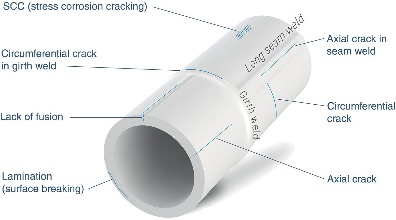
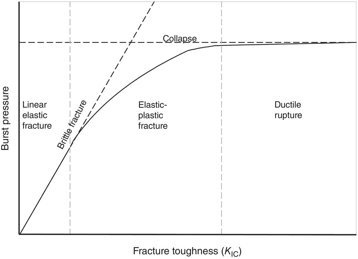
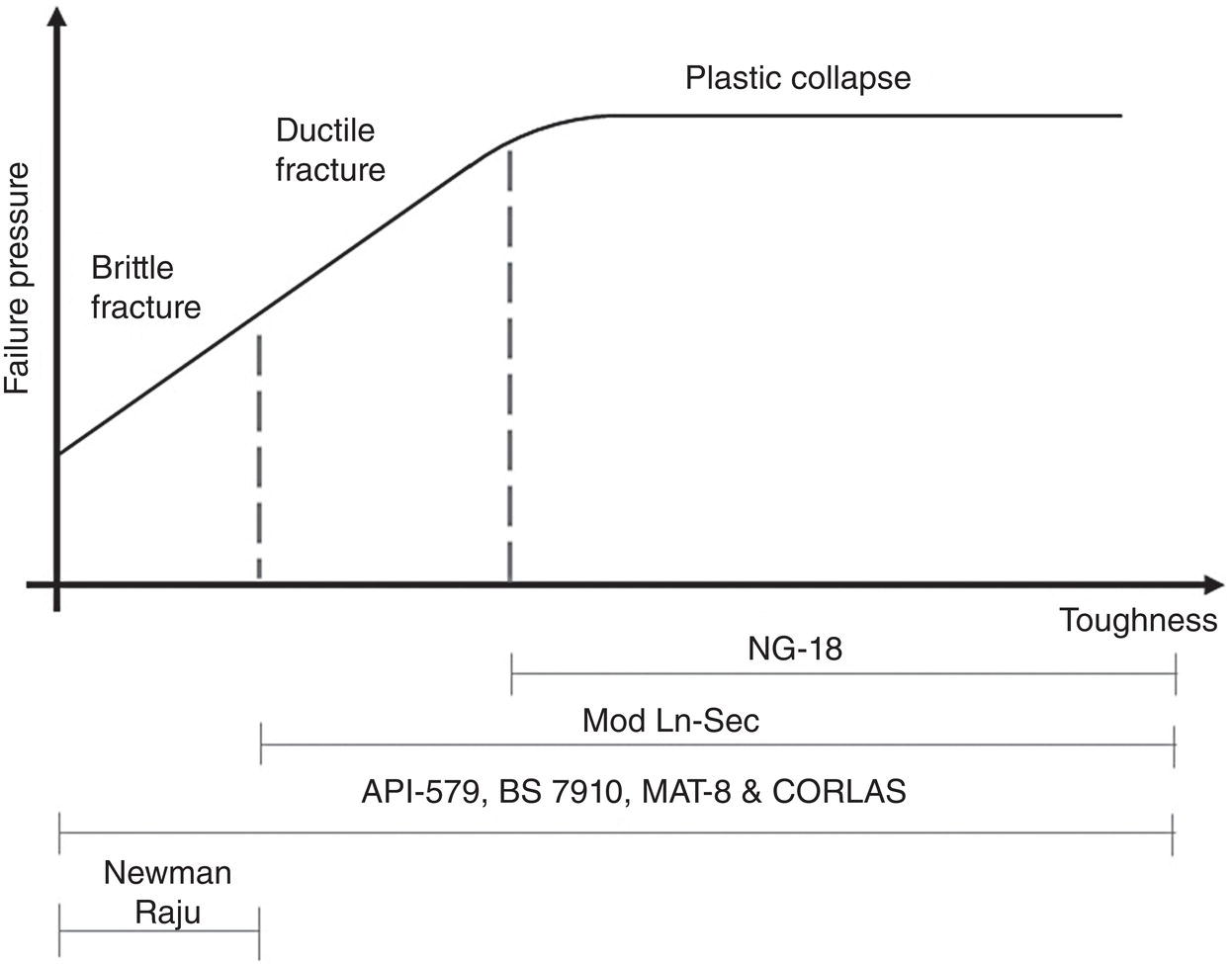
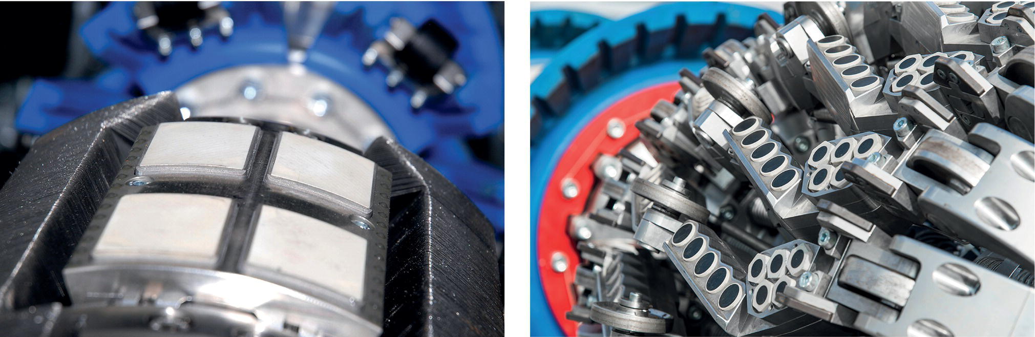
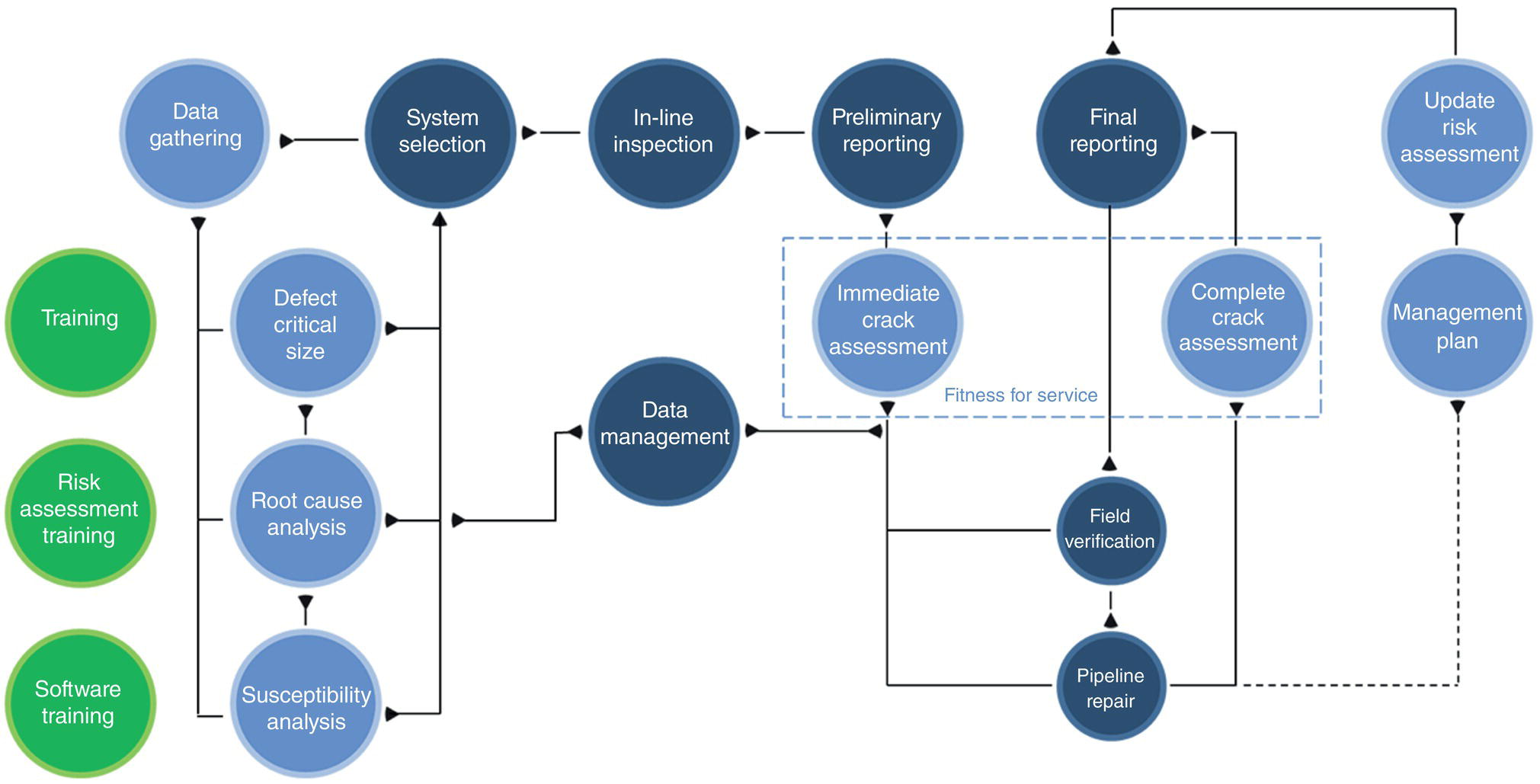
Michael Palmer ROSEN Group, Newcastle upon Tyne, UK This chapter will provide an overview of cracks in pipelines and how they can be safely managed. This covers a range of key topics, including the different types of cracks, how they develop and grow, how they can be detected, the pitfalls of treating all types of cracking in the same way, and the key aspects to be considered when assessing the integrity of pipelines affected by cracking. All those factors will be combined so the reader can see “the big picture” and identify the actions that need to be taken and prioritized in order to manage the cracking threat, with a focus on the various uncertainties that the reader will encounter. The measures that can be taken to remove, reduce, and deal with these uncertainties to produce an effective crack management plan will also be discussed. The key take-home message is that the integrity management of pipelines with cracks is not a simple endeavor—good data are key, so make an effort to understand the threat before reacting to it. Before conducting a crack assessment or trying to manage the long-term integrity of a pipeline with cracks, you need to understand what is meant by cracks and their various forms, as this will influence what happens next. The term “crack” conjures up thoughts of something troubling for most people, be it a crack in the wall of your house, a cracked engine block on your car or even a cracked egg when you open a fresh carton of eggs. All of these are cracks that we all want to avoid. Cracks in pipelines are no different, and they are a thing of nightmares for many integrity engineers. Since they show that something is not right, they can be a significant threat to the integrity of a pipeline. Throughout the history of steel pipelines, cracks have resulted in multiple high-profile/catastrophic failures and have ultimately led to the loss of human life, including in the San Bruno, California, pipeline explosion in September 2010 [1]. However, it is not all bad news, as not all cracks are an immediate threat to a pipeline’s integrity; in most cases, a well-understood, monitored, and assessed cracking threat can be managed to ensure the long-term integrity of a pipeline. The first thing is to understand what a crack is. We can turn to industry literature for a strong definition. The American Petroleum Institute’s “Recommended Practice for Assessment and Management of Cracking in Pipelines” API RP 1176 [2] defines a crack as a “very narrow, elongated defect caused by mechanical splitting into two parts.” API RP 1176 is an invaluable industry guidance document that will help you along your crack management journey. Another term that anyone dealing with cracks will need to be familiar with is “crack-like flaw.” A crack-like flaw is defined in API 579-1/ASME FFS-1 (Fitness-for-Service) [3] as a “flaw that may or may not be the result of linear rupture, but which has the physical characteristics of a crack when detected by an NDE technique.” (NDE refers to nondestructive examination.) Although most people’s instincts would suggest that all cracks are unacceptable and therefore should be removed from a pipeline, this is not always necessary. Options are available to perform an engineering critical assessment (ECA) of the anomalies to help prioritize those for investigation and repair. Before any action is taken, it is strongly recommended that a good understanding is gained regarding what is being dealt with, and by this, we mean what type of cracks they are and how could they grow (if at all possible). This will pave the way for any immediate, short, or longer-term integrity management decisions. Table 38.1 Typical Types of Cracking and Crack-Like Anomalies Found on Pipeline Systems Figure 38.1 Examples of cracks and crack-like anomalies found on pipelines. (Courtesy of ROSEN Group.) We can categorize cracks depending on when they initiated, i.e., precommissioning (manufacturing and construction) or in service. Welds (both longitudinal and girth welds) are typically hotspots for cracking due to the complexities of joining the materials together, compared to the manufacturing process of the plate steel that makes up the pipe body. However, cracking in the pipe body is also a threat to be considered. All types of cracking can propagate under the right conditions, for example, in areas of stress concentrations, residual stresses, external loads from geohazards, thermal loads, and pressure cycling during operation. Table 38.1 presents details regarding the typical types of cracking and crack-like anomalies found on pipeline systems with a basic image provided in Figure 38.1. Cracks are typically more of a challenge than metal loss when it comes to pipeline integrity management due to the dramatic way the pipe material can fail. The major difference between a metal loss anomaly and a crack is that while the metal loss anomaly will be relatively blunt, a crack has a sharp crack tip. A sharp crack tip has a much higher stress intensity around it than a blunt anomaly. This higher stress intensity means that an engineer performing the assessment of a crack should have a good understanding of fracture mechanics. Fracture mechanics is defined in API 579-1/ASME FFS-1 [3] as an “engineering discipline concerned with the behavior of cracks in materials.” A crack can fail by either fracture, plastic collapse or a mix of the two modes, and fracture occurs at stresses below the material flow stress (the point at which the material deforms significantly). Fracture mechanics models utilize a combination of stress, crack size, and fracture toughness to establish whether a crack might propagate based on mathematical models. Fracture toughness is one of the key inputs needed for a reliable crack assessment, but in many cases in the pipeline industry, it can be one of the most challenging inputs to agree on, as there is typically limited available data. For modern steels, manufacturing practices will typically lead to high toughness, which would mean that failure should be dominated by plastic collapse. However, this is not always the case and (in particular for older pre-1970s pipelines) this should not be assumed without a sound basis. There is a lot of literature available that highlights issues with long seam weld toughness in pre-1970s pipeline steel, in particular for low-frequency electric resistance welding pipe (LF-ERW) [4]. The available crack assessment models are not all suitable for modelling the full range of fracture and expert advice should be sort to determine which model is most suitable based on the understanding of the toughness of the material (the differing ranges of fracture are presented in Figure 38.2), see more detail on this topic in Section 38.3.2 (Assessment Methods). For many pipelines, it is not a requirement to perform any material testing that can help understand toughness at the time of manufacturing. This is typically the first road block when it comes to crack assessment and will be discussed in more detail in Section 38.3 (Integrity Assessment of Cracks). Cracks in pipelines can be found through: NDE will detect a combination of what would be considered cracks and crack-like anomalies, which is a major challenge in crack management. Without destructive testing, determining the type and accurately sizing the detected cracking is not straightforward. Crack-like anomalies, although having many characteristics of cracks, may not have a sharp crack tip. For example, manufacturing anomalies like a lack of fusion would have the characteristics needed to be called crack-like by NDE, but initially these would have a blunt tip that makes them less likely to grow as a crack. If the anomalies do not have sharp crack tips, assessing their integrity as cracks is overly conservative, as they would be expected to fail in a ductile manner and their failure pressure would not depend on the fracture toughness of the material. Figure 38.2 The differing ranges of fracture mechanics. (Original image, source—Michael Palmer.) Field NDE can also be problematic because for cracks, it is not a straightforward process for this particular class of anomalies. The most suitable technology for NDE depends on the type of crack that is being reviewed. As this is not known upfront, it is not always clear which technology will perform better, so a combination of technologies may be needed. Also, the competence of the field NDE technician can have a severe impact on the sizing tolerances of the provided measurements; therefore, an NDE qualification process is recommended. Moreover, a process should be put in place to ensure the correct level of detail is recorded, one that would allow for further scrutiny of the field data after the process is complete. Once the field crews have returned to the office, there will be no opportunity to improve or gather additional essential information. Therefore, NDE—both as in-field and as laboratory testing—should not be considered ground truth. Finally, it is key to understand whether cracks and crack-like anomalies can grow, meaning whether they are time-dependent. Understanding this, a crack management plan can be developed. For example, a manufacturing crack would be stable and unlikely to be a threat to the integrity of the pipeline under certain conditions, but under heavy cyclic/thermal loading, such anomalies can grow in service. An example of a stable crack would be a hook crack that survived a preservice hydrotest in a location where limited loading from pressure cycling takes place. Changes in environmental conditions (e.g., coating breakdown, CP overprotection), operation (e.g., increase in pressure cycling, upset conditions such as surge pressures), or a change in service can all impact the time-dependency of a crack and should therefore be monitored at regular intervals. Before performing an integrity assessment of cracks or crack-like anomalies, the key inputs need to be well-understood. In particular, questions regarding how representative the inputs are for the joint of the pipe being assessed should be asked. It is very easy to oversimplify crack assessments and potentially end up with a nonconservative assessment. If certain inputs have to be assumed, it is key that the impact on the assessment is understood and integrity decisions are made accordingly. For example, the integrity engineers should be questioning whether they can rely on the inputs to establish the long-term integrity of the pipe with any conviction or whether the results should be used to help prioritize potential risks while more representative input data are gathered. If in doubt, seek expert advice to support your understanding of these issues. As with any defect assessment, the main inputs that need to be understood are The yield and ultimate tensile strength of the material are always key to understanding and predicting how a pipeline will fail by plastic collapse. Although the true yield and tensile strength of a material are unlikely to be known for each specific pipe joint, the grade of steel will provide a minimum value for both the so-called specified minimum yield strength (SMYS) and the specified minimum ultimate tensile strength (SMUTS). For pipelines where there are no records and the pipe grade is assumed, it is recommended that further analysis is conducted to establish the likely grade to ensure the results of any integrity assessment are representative of the pipe being assessed. Modern ILI options now exist for pipelines with minimal to no records to support establishing the grade of pipe from a mix of inspection and verification. As discussed in Section 38.2 (What Are Cracks and How Do We Find Them?), crack-like anomalies may be detected and sized in various manners, for example, through ILI, NDE (in-field and laboratory) and destructive testing. All sizing methods should provide the length (axial or circumferential) and depth of the anomaly and in some cases a profile of the depth along the length of the anomaly. These dimensions as provided will be the starting point of the assessment. However, additional supporting information should be gathered to understand both the reliability and the sizing tolerances of the dimensions provided. To account for these errors, it is recommended that assessments be performed with an allowance for tolerance in sizing. The other key point that needs to be understood regarding dimensions is the alignment of the cracks (i.e., are they axial or circumferential), as this will have an influence on the stresses that the cracks are subjected to. First, primary stresses need to be considered. These are stresses generated by loads on the pipeline (e.g., bending, internal pressure). The first step is to understand the orientation of the cracking on the pipeline (i.e., axial or circumferential), such that Barlow’s formula can be used appropriately to define the hoop stress. In addition, the primary stress may also need to consider any influence from a change in stress state due to the influence of circular-shape deviations from sources such as bends, ovalities, roof topping, weld misalignment, and dents or axial loads. If additional stresses are likely be present, the local stresses would need to be accurately modelled; therefore, it is recommended that expert advice is sought. In addition, there may also be secondary stresses that need to be considered, that is, stresses that exist even when the pipeline is not under additional loads, such as internal material stresses due to material constraints. These are more commonly found at welds where stresses that occur during the welding process may not have been fully relieved. Various information regarding weld residual stress estimation for pipelines is available across the pipeline industry (see, for example, [5]). However, a key input for a crack assessment, in addition to the aforementioned, is fracture toughness! Indicating a material’s ability to resist crack growth, this value defines whether a crack is more likely to fail in a plastic or a brittle manner. It is dependent on temperature and varies in pipeline materials depending on the location of interest, i.e., pipe body, weld metal or heat-affected zone (HAZ). This value is often very difficult to get reliable data for, as it varies depending on the combination of wall thickness, pipe grade, manufacturer, position on the pipe (pipe body, weld or HAZ), all the way down to the batch of pipes based on the original ingot of steel. This makes it very difficult to define a value suitable for an entire pipeline; representative data for the various combinations are needed. Although this remains a hot topic in the pipeline industry, it should be noted that the only way to gain a true understanding of the fracture toughness of a pipe is based on the results of destructive testing. Various methods exist to define fracture toughness from destructive testing, such as J-integral and crack tip opening displacement (CTOD) testing. More commonly used is an indirect method of estimating toughness using correlations with Charpy impact testing. However, this is something that the integrity engineer involved in the assessment should get more familiar with, as the scatter in the data can be quite substantial. Although Charpy impact testing is typically a low-cost option, the other methods of testing provide a more accurate representation of the toughness of the material, thus improving on some of the uncertainties in the assessment. As toughness is such an important input, in the absence of accurate/reasonable toughness inputs, the engineering team involved should ensure it is familiar with the usability of the final result and ask how representative the results are when the aim is to produce failure pressure checks or a future dig plan. This, in combination with the uncertainties regarding the anomaly type and time-dependency, is where the concept of crack management comes into play. It becomes key to understand whether the results should be used to develop a detailed action plan (prioritization) with the aim of capturing the worst anomalies and gathering more data—as opposed to being able to sentence anomalies (being able to estimate that the anomaly would be unacceptable with a high degree of confidence) and understand the likely future growth. This is covered in more detail in Section 38.4 (What Can Be Done to Manage the Integrity of a Pipeline with Cracks?). Where limited credible input data are available for a crack assessment, it is recommended that expert advice is sought. Once the inputs for the assessment have been gathered and agreed upon, the next step is to select an appropriate assessment method. This is not straightforward, and expert advice should be sought before proceeding. There are various methods available, each with its own pros and cons. Some are more specific to the pipeline industry, while others are generic assessment models accepted in the pipeline industry. This is not to say that pipeline industry methods are better and care should be taken when selecting the method most appropriate for the issue. This is discussed at length in the industry, an example of which can be found in [6]. Table 38.2 includes a few details on some of the typical crack assessment methods used in the pipeline industry. As cracking has become a more prominent threat in the pipeline industry in the past few years, various other methods are also being developed, so the following list is not intended to summarize all methods available. Table 38.2 Typical Crack Assessment Methods Used by the Pipeline Industry The applicable implementation ranges for each of the methods described in Table 38.2 are graphically shown in Figure 38.3. Anomalies under complex loading or combined with other anomalies are another factor that need to be considered when selecting a suitable assessment method or even when determining whether an assessment of the combined anomalies is suitable. An example is the combined assessment of cracks in gouges or cracks affected by weld misalignment (e.g., hi-lo), as in both cases, the complexity needed for the analysis can increase significantly. Before assessment of such conditions is even considered, the available data need to be heavily scrutinized to determine what value can be extracted from the results; expert advice should be sought. It is also possible to perform probabilistic crack assessments to help reduce the conservatism within the assessment and provide a probability of failure output. Probabilistic analysis uses a distribution of values for each input. These distributions represent the known variance in a particular input. The input distributions are used in a series of simulations, and a series of results are output rather than a single-value output. The proportion of unacceptable outputs to acceptable outputs is considered the probability of failure. Such assessments require a significant amount of specific knowledge regarding the variance in the key crack assessment inputs. Probabilistic assessment should not be conducted if only limited input data are available. Figure 38.3 Simplified graphical representation of approximate applicability range of the presented crack assessment methods. (Original image, source—Michael Palmer.) Although some of the methods can be considered relatively conservative when compared to one another, it should be noted that safety factors should still be applied to ensure a specified margin of safety. This allows for any remaining uncertainties in the input data and ensures that any flaws that are near to failure are dealt with. In the described case, the flaw would be considered a “defect” when the safety factor is applied. The terminology “defect” is used in the industry to identify anomalies/flaws that need to be repaired, i.e., they do not meet the acceptance criteria. Various guidance is available regarding safety factors for crack assessment in API RP 1176 [2] and ASME B31.8S (Managing System Integrity of Gas Pipelines) [17]. However, the selected safety factor should represent an understanding of the inputs; if the inputs are considered very conservative, then consideration should be given to applying a lower safety factor. The application of a high safety factor in that instance could mean that all anomalies would be recommended for investigation and would likely be unmanageable and overly conservative. Therefore, it is recommended that a safety factor is selected that provides a balanced output based on an understanding of the uncertainties surrounding the inputs. If data are available to allow anomalies to be sentenced, then it would be appropriate to perform a review of the estimated remaining lives of the anomalies that were identified to be subcritical following the immediate integrity assessment. Growth of cracks needs to represent the likely time-dependent threat. However, as discussed in Section 38.2, it may not be possible to determine which crack-like anomalies represent which crack types based on NDE/ILI data alone. This means that you may have to conservatively treat the entire crack-like population as the most severe growth type. Typically, cracks would grow from: To effectively manage pipeline integrity when it comes to cracking, there are some specific steps that should be taken to ensure an effective management plan can be designed. As discussed in the previous sections, the first steps are to ensure you know what you are dealing with. In order to understand any threat, the first step is data gathering. Any established program needs to be continually reviewed (Plan, Do, Check, Act). A more detailed and structured set of data combined with a good understanding of the pipeline history will lead to a much better specific plan to target the threat. Understanding any details about the pipeline, such as pipe type, grade, manufacturer, vintage, coating type and condition, cathodic protection records, pressure cycling, and even construction crews and hydrotest records can be invaluable when later trying to define which points of the pipeline may be more susceptible to certain cracking threats. The processes chosen will be different depending on whether a cracking threat has been confirmed through direct assessment or not. Where cracks have not been identified yet, the integrity engineers can work with various susceptibility models to review the likelihood of there being an active, time-dependent cracking threat on the pipeline. A susceptibility model will be based on various sources of information to establish, first, if the pipeline is susceptible and can go to a level of detail to identify specific sections or even joints of the pipe that may be more susceptible. However, susceptibility assessment is only as good as the data that is input, and just because it is considered unlikely to be susceptible to a cracking threat does not mean it cannot be susceptible if the right conditions exist. For example, if sections of a pipeline were historically overprotected by the CP system but only recent records are available that show that the CP system is now maintained within the required range to avoid formation of surface hydrogen, it may be overlooked that there could be areas of coating damage and areas where SCC could have initiated. The historical operation and maintenance of the pipeline can be as important as the current operation in understanding likely cracking threats. The susceptibility assessment will also be driven by the information available. If there is only limited information available, there is little benefit in conducting a quantitative susceptibility assessment joint by joint. If cracks have been identified on a pipeline, a root cause analysis of these anomalies would bolster any long-term management plans. The root cause analysis should look to define the type of crack, when it likely initiated, and whether it has grown in service or not. This is not always possible without destructive testing. Yet, confidence in the likely threat can be gained by overlaying various information sources. However, this will be heavily reliant on the available information and can be significantly influenced by the reliability of the data gathered by the field team. If insufficient data are gathered at these crucial points in time, it can be very difficult to establish a likely cause with confidence. For example, when dealing with SCC, if pH measurements of the surface water under the coating are not taken at the time of the dig, it will not be possible to later establish the likely type of SCC without destructive testing. The as-found data can also be used to influence and refine the susceptibility models going forward and, much like the crack management plan, any crack susceptibility models should continue to be monitored and updated when new information becomes available. Where representative input data exists for a crack assessment to be performed, there can be multiple benefits to conducting an assessment to understand the critical dimensions of a crack in the early stages of the crack management process. This can assist with field response procedures and repair requirements as well as provide critical criteria to help ILI vendors highlight crack-like anomalies of concern as quickly as possible. Once likely cracking threats are established, the next stage is to determine the most suitable integrity management tools that should be utilized. These can be grouped into three categories, namely, hydrostatic tests (hydrotesting), ILI, and direct assessment. It is likely that a combination of methods will be needed to ensure the integrity of the pipeline when dealing with cracks. The pipeline is filled with water, pressurized and held at pressure for a set period of time to ensure the integrity of the pipeline. This is typically the most expensive of the integrity management options and also the least desirable, as the pipeline has to be taken out of service. There can also be complications related to the sourcing and disposing of water in an environmentally sound manner. However, a successful hydrotest demonstrates that the integrity of the pipeline is sound and provides a clear margin of safety, as it is typically done to a quantified value in excess of the maximum operating pressure/maximum allowable operating pressure (MOP/MAOP). However, a hydrotest will not confirm how many cracks are in the pipeline or where along the pipeline the cracks are that “survived” the test. Also, with any time-dependent mechanism, the pipeline would remain at risk of failure at a later date during operation. There are also possible risks regarding crack growth that require suitable hydrotest pressures and hold times to be determined to minimize this threat. In addition, for pipelines with a low resistance to ductile tearing, a hydrotest can be detrimental to the pipeline’s long-term integrity as a result of a phenomenon known as pressure reversals. In these cases, hydrotest failures can be followed by failures at a lower pressure on the subsequent retest or during the restart pressurization. To ensure the integrity of the pipeline, operators should finish on a hydrotest where a rupture does not occur. If the hydrotesting process is finished following a rupture it is unclear if other cracks were also growing during the hydrotest that would now be close to failure, i.e., where unstable crack growth stopped when the pipeline ruptured. Therefore, finishing the hydrotesting process in a controlled manner, where the pressure is gradually reduced, provides reassurance that any effects of ductile tearing would be unlikely to affect the pipeline at operational pressures, as long as the hydrostatic test pressure/MOP ratio is sufficiently high [18]. There are various industry sources available regarding hydrotesting, such as the pipeline design standards ASME B31.4 for liquids and slurries pipelines [19] and B31.8 for gas transmission and distribution pipelines [20], the pipeline integrity management standards API RP 1160 for hazardous liquid pipelines [21] and ASME B31.8S for gas pipelines [17], plus those specifically regarding hydrotesting, API RP 1110 [22] and API TR 1179 [23]. Specific guidance on hydrotesting for crack management is also further detailed in API RP 1176 [2]. There are currently two main technologies suitable for ILI detection of cracks: ultrasonic crack detection (UT-CD) and electro-magnetic acoustic transducer (EMAT), see Figure 38.4. The main notable operational difference between the two technologies is that UT-CD requires a liquid couplant to the pipe surface, while EMAT does not. This makes EMAT much more convenient to use in gas pipelines. It is possible to use UT-CD in a gas pipeline (as has been done in the past when EMAT technology was still not available), but it comes with multiple operational issues. It can also be quite challenging to ensure a successful run. In addition, introducing a liquid into a dry gas pipeline is typically best avoided, as remaining water residue can lead to a corrosive internal environment that would not occur under usual operating conditions. Current EMAT ILI technology is only suitable for detecting axial cracks (but watch this space), while UT-CD ILI technology can be set up to detect axial or circumferential cracks. However, EMAT can also be used to better understand the performance of the external pipeline coating, as it is possible to see holidays in the coating from the recorded data. Most ILI technologies will struggle to accurately size cracks with complex morphologies such as inclined high-pH SCC (SCC that does not grow perpendicular to the pipe surface) or cracks in deformations. Therefore, it is recommended that any ILI users consult with their vendor regarding their understanding of the known cracking threat prior to any inspection to ensure all parties understand what can be gained from the ILI. Figure 38.4 Crack detection ILI sensors—EMAT (left image) and UT-CD (right image). (Courtesy of ROSEN Group.) Figure 38.5 A pipeline integrity framework for cracking. (Courtesy of ROSEN Group.) When using crack detection ILI, the user should remain acutely aware that the tools are attempting to detect tight cracks, but what they record are various reflectors that have to be interpreted. The final output is a list of crack-like anomalies. As previously discussed, not all crack-like anomalies are cracks, and it is not possible to establish from the ILI data alone what type of cracks the crack-like anomalies likely are. However, there are limited options available for detecting crack-like indications for the full length of a pipeline. This is also something that all ILI vendors work tirelessly to improve upon. To help integrity engineers arm themselves appropriately, they should ensure they are familiar with the stated performance specification for the tools. Most ILI vendors will support their clients in understanding what exactly is meant by the various parts of the specification. They will work with their clients to ensure they are familiar with potential limitations in the ILI technology regarding the anomaly types that the clients are trying to detect. It is also advisable that those using crack detection ILI ensure they take the time to validate tool performance. This may require a significant number of digs to ensure they gain confidence in the ILI findings to manage the integrity of the pipeline. Guidance is available to support an ILI user with this validation process in API 1163 (ILI System Qualification) [24]. To gain the most from a crack detection ILI and to support the integrity management of a pipeline, a wider approach that considers all aspects of crack management is recommended. An example of one such method is the ROSEN Pipeline Integrity Framework for cracking [25] (see Figure 38.5), which combines all of the key elements and expertise needed to ensure the cracking threat is well-understood. It starts with understanding the root cause of any cracking, what defect sizes would be considered critical and which areas are most susceptible. By combining these elements, you can increase your knowledge of the cracking threat and optimize the selected inspection technologies to ensure that the response is informed and proportional to the level of the threat. The process continues by ensuring that a good understanding of the ILI performance is gained as well as ensuring that the crack-like anomaly calls from the ILI (based on the crack-like reflectors identified by the ILI) are better understood through field verification. This feedback loop with the ILI vendor is essential to refining ILI sizing and classification, which in turn will reduce uncertainties and improve future dig planning. During the digs, there is also an opportunity to better understand any pipeline-specific or environmental drivers to help refine the crack susceptibility models. This is then closed out through updating the risk assessment and management planning before the next cycle of crack integrity management begins. This next cycle will benefit from the improved understanding of the cracking threat based on the information gained during the recently conducted cycle. Although this section has concentrated on crack detection technologies, it is vital to note that other noncrack detection ILI technologies can be invaluable in supporting the crack management effort. For example: This involves in-field investigations and NDE of selected sites based on the susceptibility results or risk assessment. Digs should be conducted in locations of both high and low susceptibility to ensure the model is working appropriately and no relevant contribution is being overlooked. Typically applied when targeting SCC, this method is known as SCCDA. The processes involved in SCCDA are documented in NACE SP0204 [26]. The key to any SCCDA process is upfront data gathering and ensuring a thorough understanding of the pipeline, as discussed in Section 38.4.1 (Understanding the Threat). NACE SP0204 SCC (direct assessment methodology) breaks the process down into four steps: Direct assessment can also be opportunistic, for example, while investigating another pipeline threat such as corrosion. NDE such as MPI can be conducted to check for cracking. Increasing the number of data points and confirming if cracks are present or not using opportunistic digs will help improve the understanding of the cracking threat. By comparing the direct assessment findings against a crack susceptibility model it is possible to better understand the cracking threat and the performance of the susceptibility model. For example, if cracks are found and the susceptibility to cracking is currently considered low this indicates that further improvements are necessary to understand the crack threat drivers and improve the susceptibility model. It is paramount that integrity engineers using these integrity management tools take the time to understand what the likely remaining uncertainties are following their use. Examples include In many cases, a mix of integrity management tools can be beneficial. Examples include When it comes to establishing a plan regarding how to best manage the integrity of a pipeline with cracking, this needs to concentrate on filling knowledge gaps. These knowledge gaps will likely relate to what exactly the crack-like anomalies found represent in regard to the type of cracking, key inputs to the crack assessment and outstanding issues not answered by the chosen integrity management tools. An understanding of the knowledge gaps will also help dictate what level of assessment should be performed when it comes to susceptibility and risk assessments. Note that the risk assessment will be the driving factor in the long-term management of the cracking threat. A risk assessment is based on a combination of: Risk assessment is not a simple topic and expert advice should be sought. While there remain significant information gaps during the initial stages of crack management, a risk assessment based on a qualitative approach may be needed initially. As the information gaps are closed, it may be possible to implement a quantitative approach. For pipelines that operate in areas of high consequence, it may be necessary to prioritize filling knowledge gaps in these areas more promptly to allow a for a more-detailed risk assessment to be performed. The method selected should align with the objectives and the anticipated outcome of the assessment. The management plan will take all the key aspects and understanding of the cracking threat to manage the identified threat going forward. It will be aimed at closing any knowledge gaps before the next review point, continuing to build on the key information needed to improve susceptibility models, etc., while also ensuring the integrity of the pipeline through any planned digs from the integrity and risk assessments. It will also need to consider if/when any further integrity tools (e.g., ILI, hydrotesting) need to be implemented. A detailed management plan should consider and weigh up the validity of applying a range of options to support the integrity of the pipeline and reduce crack growth. Possible options are Once a crack management plan is in place, the next step is to ensure that the performance of the plan is adequate. This is done by implementing various performance measures, reviewing how well, how much, and how effective the items from the plan were. Various key performance indicators should be put in place to support this evaluation. This process should be continuous, and it should review the plan’s ability to remove/manage critical defects while also identifying whether the plan was overly conservative and could be improved upon in future iterations. Finally, as cracking threats are a much more significant threat for pipelines that transport hydrogen due to the impact on steel toughness, etc., crack management should be high on the list of priorities when it comes to repurposing pipelines for transporting hydrogen. This is further discussed in Chapter 39, “Hydrogen and the Energy Transition.”
38
Integrity Management of Pipelines with Cracking
38.1 Introduction
38.2 What Are Cracks and How Do We Find Them?
Cause of Anomaly
Types of Anomalies
Comment
Manufacturing/construction
Environmentally assisted cracking
Mechanical damage
38.2.1 Key Learning Points
38.3 Integrity Assessment of Cracks
38.3.1 Assessment Inputs
38.3.1.1 Tensile Properties
38.3.1.2 Anomaly Dimensions
38.3.1.3 Pipeline Stresses
38.3.1.4 Fracture Toughness
38.3.2 Assessment Methods
Method
Type
Synopsis
Comments
References
NG-18 (flow stress)
Pipeline-specific
[7]
Modified Ln-Sec
Pipeline-specific
[8, 9]
Newman-Raju
Generic
[10]
API 579-1/ASME FFS-1 Part 9 Lv 2/BS7910 Option 1
Generic
[3, 11]
CorLASTM
Pipeline-specific
[12–14]
PRCI Mat-8
Pipeline-specific
[15, 16]
38.3.3 Crack Growth
38.3.4 Key Learning Points
38.4 What Can Be Done to Manage the Integrity of a Pipeline with Cracks?
38.4.1 Understanding the Threat
38.4.2 Integrity Management Tools
38.4.2.1 Hydrotesting
38.4.2.2 In-Line Inspection
38.4.2.3 Direct Assessment
38.4.2.4 Summary of Integrity Management Tools
38.4.3 Longer-Term Crack Management
38.4.4 Key Learning Points
References