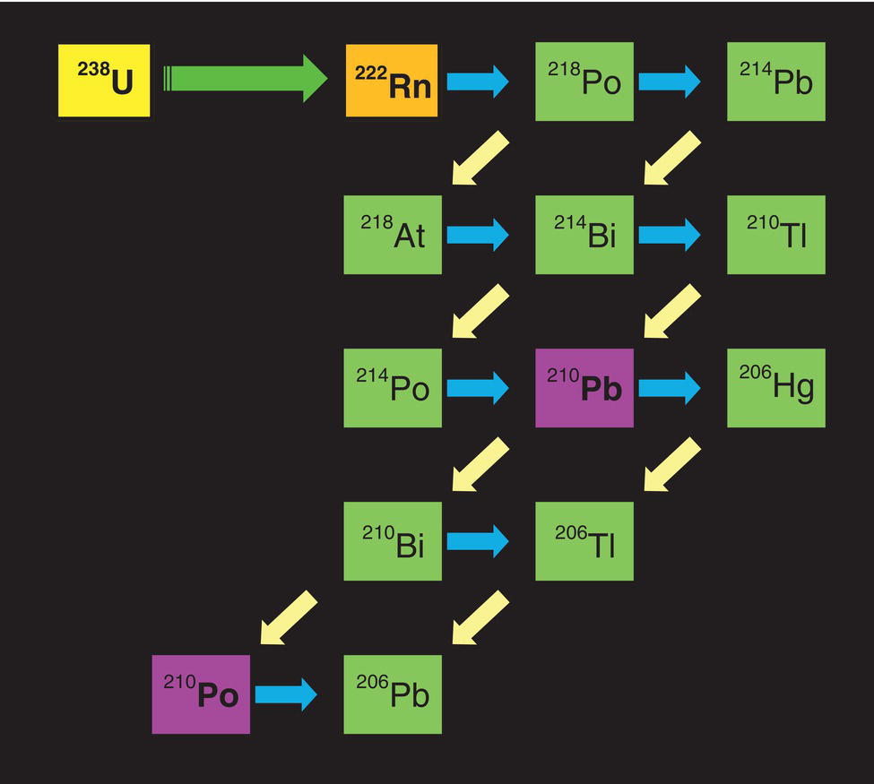
Abdelmounam M. Sherik Research and Analytical Services Department, Saudi Aramco, Dhahran, Saudi Arabia In the oil and gas industry, the term “black powder” is a color-descriptive term typically used to describe the appearance of a blackish particulate material that collects in sales gas transmission pipelines [1–12]. Black powder is a worldwide menace experienced by most, if not all, transmission gas pipeline operators with internally uncoated pipelines. Black powder can be found in different forms, namely, dry fine powder, wet with tar-like texture, or as a slurry. Black powder has been found in recently commissioned as well as in long-service gas transmission pipelines. Figure 62.1 shows that black powder is composed of fine particles when examined at high magnification under the scanning electron microscope (SEM). Figures 62.2 and 62.3 show dry and wet tar-like black powder, collected at a filter station and scraper receiving door, respectively, of gas transmission pipelines. Case histories show that large quantities of black powder can accumulate over a period of time inside pipelines and at pipeline filter stations. For example, 55,800 kg (123,018 lb) of black powder was removed by mechanical pigging from a 1210 mm (48 in.) 170 km (106 miles) sales gas pipeline by one operator in the Middle East, 3600 kg (7937 lb) of black powder was removed from a 400 mm (16 in.) 80 km (50 miles) gas pipeline in Houston, and approximately 7000 kg (15432 lb) of black powder was removed over a period of 6 months using cyclone separators from a 914 mm (36 in.) Greek sales gas transmission pipeline extending for a distance of 12 km (7.4 miles) [8]. The need to manage such large quantities of black powder can add millions of dollars in operating expenditures including repair and maintenance of control valves, pipeline cleaning, and handling and disposal, as well as require additional capital expenditures including installation of new separators (to be discussed in Section 62.7.1.2). Black powder is mainly composed of various forms of corrosion products, typically iron sulfides, iron oxides, and iron carbonate, mechanically mixed or chemically combined with any number of contaminants such as salts, sand, liquid hydrocarbons, metal debris, and steel mill scale [1–12]. Typically, the corrosion products make up over 80 wt% of the black powder, and the remaining 20% is contaminants [8]. Different gas pipeline operators report different corrosion products for the black powder removed from their sales gas pipelines. For example, some gas operators reported their black powder as being predominantly iron sulfides [9]; others report the complete absence of iron sulfides, but the presence of iron oxides and hydroxides [1, 2, 4–8, 10–12], while others report a combination of all these products (iron sulfides, iron carbonates, and iron oxides) [3]. Regardless of its composition, black powder has a relatively high specific gravity (sp.gr. 4–5.1), is abrasive, and is typically difficult to remove in routine pipeline cleaning operations [8, 12]. The different forms of black powder have one common source: they are all formed inside sales gas pipelines as a result of corrosion of the internal walls of these lines. Although corrosion is the common cause for all forms of black powder, black powder is a complex phenomenon that is strongly affected by a multitude of factors, including pipeline construction history, dehydration process, commissioning practice, gas composition, service life of the line, and network design. These factors, in many cases, are unique to a specific line within a network. It is important to understand these complex factors to identify the source(s) of black powder, in a specific pipeline, and in turn to devise ways to manage it. Because of this stated complexity, generalized conclusions and “one-solution-fits-all” scenarios might not be valid for all situations. Figure 62.1 Typical scanning electron microscope (SME) image of comingled black powder particles at the pig receiving door. Figure 62.2 Very fine black powder collected in cartridge filter elements at a filter station on a sales gas pipeline. Figure 62.3 Tar-like black powder collected at the scraper door receiver of a sales gas pipeline. Black powder could have major adverse effects on pipeline operations and sales gas customers, alike [1–12]. For example, black powder could Figure 62.4 A control valve casing that was eroded by black powder. Arrows point to eroded locations. (Courtesy of Saudi Aramco.) Figure 62.5 Carbon steel control valve cage that was eroded by black powder in 45 days of service. (Courtesy of Saudi Aramco.) As stated earlier, black powder is formed inside sales gas pipelines as a result of corrosion of the internal walls of these pipelines. Water is a prerequisite for corrosion to occur, and therefore it is important to identify the potential sources of water moisture in these pipelines (transporting what should be dry gas). Also, it is important to understand the electrochemical reactions that lead to the various corrosion products in order to identify the corrosion mechanism responsible for black powder and develop appropriate mitigation methods. In typical sales gas production, triethylene glycol (TEG) is used to remove water moisture from the produced natural gas to reduce its water dew point below the lowest temperature found in transportation operations. In the Middle East, and in similar temperature regions (for example, southern USA), transmission gas is dried to a maximum water moisture content of 7 lb/MMSCF. In contrast, in colder regions such as Canada and northern Europe, sales gas specifications are set to a maximum water content of 4 lb/MMSCF. Because of this drying process, it is often perceived that the threat of internal corrosion in dry sales gas pipelines is highly unlikely, or non-existent, because it is believed that no water condensation will occur, and therefore no internal corrosion can occur. However, field observations show that even under dry sales gas specifications, general internal corrosion is widely encountered, leading to the formation of black powder in these lines [1–13]. The reason for internal corrosion in nominally dry gas pipelines can be attributed to the fact that it is not normally possible to completely eliminate moisture from these pipelines [1–13]. Liquid water may be brought into the pipeline network by poor hydrotesting practices, condensation, or intrusion from lateral components [14]. Poor hydrotesting practices can lead to residual water remaining in the pipelines due to incomplete dewatering and drying procedures during hydrotesting. Drying practices (e.g., use of nitrogen gas, hot air, and dry sales gas) are most influential in promoting corrosion during and immediately after pipeline commissioning. Corrosion attributed to poor hydrotesting practices is expected to decrease rapidly with longer service life of the pipeline as the residual waters are continually removed during cleaning operations of the lines [15]. Water condensation onto the internal surfaces of sales gas pipelines can occur under the following conditions: Water vapor can potentially condense on the inner walls of the pipeline due to high water dew points resulting from the presence of hygroscopic salts (e.g., NaCl and MgCl2) deposited on pipeline internal surfaces [16–18]. These salts can absorb water from the gas (even though the gas meets the 7 lb/MMSCF or 4 lb/MMSCF water moisture specifications) and promote corrosion and the formation of black powder. The source of salts is normally the pipeline hydrotest procedure, especially in regions where sweet water is not readily available in the field, such as the case in the Middle East. In these regions, it is recommended that prior to commencing the hydrotest drying step, the pipe internals are washed to remove the salts. This can be achieved using fresh sweet water slugs between pigs. The corrosion attributed to the presence of hygroscopic salts is expected to decrease rapidly with increasing service life of the pipeline as these salts are continually removed during cleaning operations of the lines [15]. TEG from the dehydration unit can enter the network in the form of TEG vapor and liquid TEG carryover. TEG has high affinity for water (hygroscopicity), and when present in the sales gas pipeline, it absorbs water from the gas (even though the gas meets the 7 lb/MMSCF or 4 lb/MMSCF water moisture specifications), forming TEG–water homogenous mixture solutions. These solutions are high in TEG content, typically in the range of 95–99.5 wt% TEG [19–21], and can be slightly corrosive to pipe steel. HYSYS simulation using the operating conditions of a gas treating plant, with 7 lb/MMSCF water specification, showed that the composition of the condensed TEG-water solution is 97.66 wt% TEG and 2.34 wt% water [19–21]. Both cases (on-spec and off-spec gas) result in excess water moisture in the network, which condenses on the internal surfaces of the pipes, leading to internal general corrosion (i.e., black powder formation). Moisture intrusion occurs in networks where the main gas transmission pipelines are fed by different gas treating plants and interconnected by crossovers. In such a network configuration, if one gas treating plant does not meet gas moisture specification, the whole network becomes affected. Internal corrosion of sales gas pipelines can occur when H2S, CO2, and O2 gases present in the sales gas become dissolved in the condensed water moisture and TEG–water mixture solutions. The water moisture containing the dissolved gases reacts with the steel surface, leading to its corrosion (formation black powder). These reactions are electrochemical in nature and have well-established mechanisms. The following are simplified electrochemical reactions that describe these corrosion processes and their respective corrosion products. It is important to note that in all of these electrochemical reactions, condensed water is a necessary condition for these reactions to proceed. Carbon dioxide (CO2) is a naturally occurring constituent of natural gas. The source of the siderite–FeCO3 corrosion product is the chemical reaction of dissolved CO2 in the condensed moisture, producing carbonic acid, which in turn reacts directly with the steel surfaces to produce FeCO3, in accordance with these reactions [22–24]. Iron sulfide (FeS) corrosion products are usually formed from H2S reacting directly with the steel wall of the pipeline as per the following reactions [25, 26]. Hydrogen sulfide (H2S) can also be a naturally occurring constituent of natural gas or alternatively, produced by sulfate-reducing bacteria (SRBs). These anaerobic bacteria use the reduction of sulfate as a source of energy and oxygen, in accordance with reactions such as It is important to note that condensed water is a prerequisite for these bacteria to thrive and multiply, and as such, the above reaction cannot occur in the absence of water. Oxygen is not a natural constituent of sales gas, but it can ingress during gas-treating operations and gas transportation. For example, oxygen could ingress through leaks at low pressure points throughout the pipeline network or is inevitably introduced due to the use of technical-grade nitrogen gas in blanketing of TEG storage tanks. Technical-grade nitrogen normally contains 3 wt% oxygen. Pipeline pigging operations are also another intermittent source of oxygen entry to the gas network. A 1988 survey of 44 natural gas transmission pipeline companies in North America indicated that their gas quality specifications allowed maximum O2 concentrations ranging from 0.01 mol% (100 ppmv) to 0.1 mol% (1000 ppmv) with a typical value of 0.02 mol% (200 ppmv) [27]. The actual values of O2 in the gas stream were low, ranging from 0.0 mol% (0.0 ppmv) to 0.02 mol% (200 ppmv). It has been shown that the oxygen content of approximately 0.001 mol% (10 ppmv) has little effect on steel corrosion in the presence of stagnant water inside gas transmission pipelines, while 0.01 mol% (100 ppmv) produces fairly high corrosion rates. As a general rule of thumb, it is recommended that gas transmission pipelines should consider limiting maximum oxygen concentrations to 0.001 mol% (10 ppmv) [14, 27]. In cyclical wet–dry low dissolved oxygen environments, as is the case in sales gas, iron oxides are usually formed by the direct oxidation of pipeline steel walls, in accordance with the following reactions [22, 28]. In waters containing low concentrations of dissolved oxygen, as is the case in the sales gas environment, the γ-FeO(OH) is unstable and will quickly transform to magnetite–Fe3O4 and water by the following reaction [22]. But if the water is nearly saturated with dissolved oxygen, then hematite (Fe2O3) is often present [23]. Alternatively, iron oxides may be formed due to microbiologically induced corrosion (MIC) resulting from acid-producing bacteria (APB). Once again, condensed water is a prerequisite for these bacteria to thrive and multiply, and as such, MIC cannot occur in the absence of water. In reality, a combination of these three gases (H2S, CO2, and O2) is typically present simultaneously in gas pipelines. Which corrosion product forms is mainly a function of the partial pressures of these gases. For example, concentrations of H2S and CO2 gases determine the corrosion type (H2S and CO2 corrosion) and the type of corrosion products (i.e., black powder). According to Kermani et al. [29], there are three corrosion domains for mixed carbon dioxide/hydrogen sulfide systems, which can be represented by the ratios of their partial pressures in the system: The above ratios are based on the original work by Dunlop et al. [30] published in 1983. Smith [31, 32] has investigated the origins of the Dunlop ratios and reported that these ratios were developed for low ionic strength solutions at a temperature of 25 °C. These key assumptions cover a narrow range of oilfield environments. Smith proposed that a CO2/H2S ratio of below 1 (sour corrosion) and above 5000 (sweet corrosion) is more accurate. Matters become more complicated when oxygen is present along with CO2 and H2S gases in the pipeline. In this case, the corrosion product (black powder) is composed of siderite, iron sulfides, iron oxides, and elemental sulfur. Elemental sulfur is formed by the reaction between O2 and H2S [33]. In general, the corrosion rate increases with increasing oxygen partial pressure [34]. Table 62.1 summarizes the main products of black powder and their potential sources. Table 62.1 Compounds in Black Powder and Their Respective Potential Sources Knowledge of the black powder formation rate in sales gas transmission pipelines is an important parameter that can assist pipeline operators in the design and selection of the proper separator technology (Section 62.7.1.2). Several laboratory studies have been conducted on carbon steel coupons exposed to different simulated sales gas compositions and conditions reported a corrosion rate in the range of 0.025–0.14 mm/year [33–36]. These studies were conducted by exposing (by full immersion or dewing) the steel coupons to thin films of deionized water containing no salts or TEG. The corrosion rate of carbon steel exposed to simulated sales gas environments under dewing conditions in the presence of a hygroscopic salt (NaCl salt deposited on the carbon steel coupons) was experimentally measured to be 0.11 mm/year [17, 18]. Several studies [19–21, 37–39] conducted on carbon steel exposed to TEG–water mixture solutions under simulated sales gas compositions showed that these mixtures can cause corrosion, albeit at significantly lower corrosion rates than the corrosion rates caused by condensed pure water. The corrosion rates caused by TEG–water mixtures are typically 1–5% of their counterparts caused by pure condensed water [19–21, 37–39]. Even at these very low corrosion rates, high quantities of black powder could form in long and large pipelines over time, particularly if these lines are not cleaned regularly [21, 38, 40]. Saudi Aramco’s field experience, based on measuring the amount of black powder (dry iron oxides) removed after 6 months from chemical cleaning of several sales gas transmission lines with known lengths and sizes, indicated that the black powder formation rate in the range 0.025–0.07 mm/year. A similar study conducted by Statoil-Norway to estimate the black powder formation rate based on the amount of black powder (dry FeS) removed from the first 10 km of a fully TEG wetted sales gas pipeline indicated a corrosion rate of 0.004 mm/year [40]. This field-calculated corrosion rate is aligned with laboratory studies conducted in TEG–water mixtures [38–40]. Pipe wall thickness losses resulting from these low corrosion rates do not impact the integrity of the pipe, but the amount of generated black powder, especially in large and long pipelines, has major impacts on pipeline operations and customers, as previously mentioned in Section 62.2. The importance of analysis and identification of the organic and inorganic contents and particle size range of black powder cannot be overemphasized. Accurate analysis of black powder is important for many reasons. For example, accurate analysis is essential in selecting the proper chemical cleaning procedure and chemistry, identifying the corrosion mechanism responsible for the formation of black powder and developing appropriate mitigation methods and also in developing a proper disposal strategy. Results of the analysis are as good as the quality of the analyzed samples. Accurate sample analysis starts with accurate collection of representative black powder samples and their proper handling and storage [1, 3, 22]. Because of collection convenience, black powder samples are normally collected at receiving traps or filter stations where black powder is accumulated either by pigging operations or by the filtration process. In both cases, the collected samples do not represent black powder that have formed at well-defined conditions (specific location and time) in the pipeline. They instead represent comingled samples collected from the sum of black powder products that have formed at different locations and times along the pipeline [41]. In long pipelines, especially if interconnected by lateral lines, analysis of comingled black powder samples can lead to incorrect conclusions regarding the corrosion mechanism as well as particle size and particle size distribution. The drawbacks of this collection method can be overcome by selection of the correct collection points and analysis of several samples from the same removed black powder pile and from multiple cleaning runs. Another approach for collecting black powder samples is through the use of the iso-kinetic sampling technique. This is an in-line collection method which can be carried out through the insertion of an iso-kinetic sampling probe inside a gas pipeline [42, 43]. The field setup contains a probe that is inserted into the gas pipeline at the appropriate location and has a flow meter and control valve to adjust the flow rate to maintain the same flow rate of the gas in the sampling apparatus as the main pipeline. The main advantage of this collection method is that it can capture gas-entrained black powder particles at discrete locations and times along a pipeline. Because of the cost and potential safety concerns associated with this collection approach, this method is less widely used, unless the exact particle size distribution and solid loading is required. Table 62.2 summarizes general considerations and specific issues related to black powder sample collection. The following PRCI report provides general guidelines for internal corrosion sample collection. Regardless of the collection method, the collected black powder samples are subjected to various tests to determine their organic and inorganic composition. Table 62.2 General Considerations and Specific Issues Related to the Collection of Black Powder Samples Test methods can broadly be divided into two categories: (1) field spot tests and (2) laboratory tests using advanced analytical techniques. Due to the large pipeline networks and their geographical locations, often times, in remote regions away from well-equipped testing laboratories, it is common practice in the oil and gas industry to test corrosion products using simple spot tests such as the use of acids or magnets to test for certain corrosion products [1, 22]. But these simplified methods can be completely inaccurate and therefore are often misleading. For example, a drop of acid on a corrosion product could make this corrosion product to effervesce, which suggests that this product could be either iron carbonate (FeCO3) or calcium carbonate (CaCO3) [22]. These two products have completely different formation mechanisms and sources, where the former is a corrosion product and the latter is a scale. Not knowing positively, the product being tested leads to erroneous conclusions and mitigation actions. Likewise, the different forms of iron sulfide react differently with acid spot-test. For example, mackinawite is highly reactive with hydrochloric acid, evolving H2S gas. But the other forms of iron sulfides such as pyrrhotite, troilite, marcasite, and pyrite are less reactive with HCl, and much less or no H2S is evolved during the short time of an acid spot test. Therefore, an acid spot-test failing to make the product evolve H2S does not guarantee that a black powder sample is free of sulfides. Similarly, if a product was found to be magnetic when using magnetic spot-tests, it is often assumed that the product is magnetite (Fe3O4). But greigite (Fe3S4) is also magnetic and has black color as Fe3O4 and the two compounds are formed under entirely different circumstances [22]. Analytical laboratory techniques such as scanning electron microscopy (SEM), energy-dispersive X-Ray (EDX), X-ray diffraction (XRD), Fourier-transform infra-red (FTIR), thermal gas analysis (TGA), gas chromatography/mass spectroscopy (GC/MS), and quantitative polymerase chain reaction (qPCR) can be used to determine the inorganic and organic compositions of the black powder samples as well as their particle size and microbial content. The EDX technique has been used to analyze the inorganic composition of black powder. However, this technique provides only elemental analysis and not compound compositional analysis. For example, in black powder samples that contain various compounds of iron oxides (e.g., Fe3O4, FeO(OH), and Fe2O3), the EDX technique is unable to ascertain which of these compounds is present, but it can only inform the investigator that the elements Fe and O exist in the analyzed black powder sample. It is left to the investigator’s judgment to infer from this elemental information as to which compounds are present, which is an impossible task. XRD is the appropriate technique to use to positively identify the exact compounds of the collected black powder samples. With the correct identification of the corrosion products, the electrochemical reactions illustrated in Section 62.3.2 can be used to arrive at the source of these corrosion products and develop an appropriate mitigation strategy. The XRD technique requires a small amount (usually 1 g) of black powder and produces full compound compositional analysis of the sample analyzed. Wet tar-like or slurry black powder samples collected from transmission gas pipelines should also be analyzed for their organic content. Fourier-transform infra-red (FTIR), thermal gas analysis (TGA), and gas chromatography/mass spectroscopy (GC/MS) techniques are the appropriate test methods for this purpose. These analyses will show the type and weight content of organic liquids found in the analyzed samples. The liquid phases can be a mixture of triethylene glycol (TEG) and hydrocarbon-based liquids such as compressor oils. The presence of such hydrocarbon liquids in black powder is indicative of an operational problem such as excessive TEG liquid carryover and compressor oil leaks. Table 62.3 Solids Loading and Particle Size Distribution of Black Powder Particles in Gas Sampled by the Isokinetic Sampling Technique Also, collected black powder should be analyzed for its bacterial content, more specifically for sulfur-reducing bacteria (SRB) and acid-producing bacteria (APB) using conventional cultivation media or DNA analysis techniques such as quantitative polymerase chain reaction (qPCR). Conventional cultivation media methods can only detect live bacteria; however, DNA analysis techniques can be used to detect bacteria that are dead as a result of poor sample preservation. Bacterial analyses, particularly DNA analysis, are warranted, especially if localized corrosion attacks with morphologies that are characteristic of MIC are observed on the internal walls of the lines. Determination of black powder particulate size and size distribution is important for the proper design of filtration/separation systems. SEM or optical microscopic techniques equipped with image analyzers are most commonly used to determine particulate size and particle size distribution (SDP) of comingled black powder particles collected from filters or at scraper receiving doors. Similar analysis can be performed on samples collected by the iso-kinetic technique. Solid loading defined as the ratio of the black powder particles suspended in the gas in a given volume of gas, typically expressed in mg/MMSCF, is a required measurement for the proper design of separator systems and for assessing the effectiveness of pipeline cleaning operations. Proper determination of black powder loading requires sampling of the gas at different locations along the pipeline and at different depths inside the pipe, which is typically carried out by the iso-kinetic technique. Table 62.3 shows results of solid loading and particle size distribution of black powder particles entrained in the gas, as sampled by the iso-kinetic sampling probe at two different sampling point locations and at normal pipeline operating conditions [44]. Black powder particles entrained in the gas can have a number of adverse impacts on pipeline operations and customers alike. Once black powder starts to move with the gas, it will continue to move until the gas flow rate is reduced or the gas is compressed. Operators report that when black powder moves, it shatters and becomes very small in size, in the range of 1 micron or less, making it difficult to filter and possibly easier to move [45]. Moving black powder particles can present major health and environmental hazards, trigger erosion and/or clogging of control valves and metering instrumentation, and impact customer operations and product quality in numerous ways. These together lead to significant increases in costs. Knowledge of the threshold gas velocity required for the dislodgment and entrainment of black powder particles can significantly assist gas operators in designing the proper filtration systems and in providing advance warning to downstream operations of incoming black powder particles. According to Smart [46], when black powder is moved through the pipeline by the gas flow, the gas threshold velocity required to move dry solids in a pipeline can be calculated and depends on pipeline diameter, gas pressure, density, viscosity, and particle size and density. For instance, typical gas threshold velocities required at a gas pressure of 1000 psi are 10 ft/s for 8-in. pipelines, 13 ft/s in 24-in. pipelines, and 14 ft/s in 48-in. pipelines [46]. E. Elsaadawy and A. Sherik conducted a computational fluid dynamics (CFD) study to predict the movement and settlement of black powder particles in sales gas pipelines [47]. Pipe sizes in the range 24–56 in., gas velocities of 10 and 20 m/s, and black powder particles with sizes in the range between 2 and 20 μm were studied. The study showed that the particle distribution inside the pipelines was insensitive to the pipe size in the range of velocities and pipe sizes studied. Their work also showed that at the examined gas velocities, black powder particles will be suspended into the gas stream and continue to flow downstream, unless obstructed by a bend or a valve where the sudden changes in direction inside such components may promote particle segregation. They concluded that filter systems installed onto such pipelines should be sized considering the fact that all of the particles size spectrum should be collected in the filtration vessels. The reader is encouraged to consult references [46–53] for more information on movement of black powder in sales gas pipelines. The hardness and shape of eroding particles strongly determine the extent of the erosion damage that these particles can inflict on the impacted equipment. The hardness of black powder is an important mechanical property to understand the erosive properties of black powder particles and assists in the selection of equipment such as separator systems and pressure control valves. In one study [6], the hardness of black powder was measured using two different techniques: (1) microhardness measurement of solid-state sintered comingled black powder particles and (2) nano-indentation of individual black powder particles. Comingled and individual black powder particles were collected at a pig receiving door and in-inline using the iso-kinetic probe, respectively. Hardness values of 498 ± 62 VHN (49 ± 4 Rc) and 475 ± 164 VHN (47 ± 10 Rc) were measured by the microhardness and nano-indentation techniques, respectively [6]. The large standard deviation in hardness measurements using the nano-indentation technique is attributed to the fact that hardness indents were made into individual particles, which could be of differing compositions (iron oxides or iron carbonates), which are known to have different hardness values [6]. It is obvious from these hardness values and the jagged shape (Figure 62.1) of black powder that black powder particles can rapidly erode many engineering materials such as pressure control valves made of carbon steel (average hardness value of 87Rb), as can be seen in Figures 62.4 and 62.5. Akbarzadeh et al. [54] investigated the solid particle erosion behavior of 12 control valve candidate materials for use in the sale gas transmission pipeline. The erosion rates were measured using impinging jets of Fe3O4 particles at two different particle sizes (6.9 and 30.4 μm), two different velocities (90 and 130 m/s), and six different impingement angles (15°, 30°, 45°, 60°, 75°, and 90°). The most erosion-resistant materials were found to be tungsten carbide (WC) and Stellite 12, and the least erosion-resistant materials were nickel-plated A1018 carbon steel and A240 type 410 stainless steel plates. Elsaadawy and El-Sherik [55] conducted a computational fluid dynamics (CFD) analysis to investigate the erosive behavior of black powder on a pipeline ball control valve. The study showed that the maximum erosion rate takes place on the inside wall of the ball, directly downstream of the inlet, and on the wall just before the outlet on the body (this while the valve was partially closed at 45°). It was also shown that using Stellite 12, instead of A-105 carbon steel and A-505 carbon steels for the body and ball of the valve, respectively, could considerably reduce the erosion rate of the valve [55]. Based on these studies, Saudi Aramco has retrofitted CS control valves with trims designed to resist erosion, such as solid tungsten carbide for valve cages and tungsten carbide inserts for valve plugs and seat rings. Another CFD study [56] published by the same authors examined the erosive effects of black powder particles on pipeline bends with different radius of curvature to pipe diameter ratios (R/D = 1.5 and 3.0). The study showed that a pipeline bend with a longer radius of curvature will have a more uniformly distributed erosion over the outer wall of the bend, which makes it a better candidate for applications in severe erosive service environments such as sale gas pipelines loaded with black powder. However, the erosion rates in both cases are negligible and should not affect the operational life of the bends. There are several removal and prevention methods available to gas pipeline operators to mitigate the formation of black powder and manage its impacts [1, 3, 41, 43, 57, 58]. Typically, there is no single best solution to control black powder. For example, in the case of existing uncoated pipelines, strict adherence to gas specifications namely, water moisture and TEG vapor loss contents in the gas entering the network, would ensure elimination of condensed moisture and in turn the formation of black powder. However, because of the inevitability of process upsets, excess moisture may enter the line grid, leading to potential condensation and internal corrosion. Therefore, the optimum black powder management practice usually consists of a combination of several control methods that must include moisture control coupled with downstream removal methods such as filtration. In contrast, in the case of new pipelines, internal coatings primarily used for drag reduction provide a cost-effective and economical solution for the prevention of black powder. Generally, pipeline companies practice various methods to manage and control black powder in their gas networks. Management approaches can broadly be divided into two categories: (1) removal and (2) prevention strategies. Black powder products tend to have a high density (e.g., approximately 4–5.1 g/cm3) and are abrasive and difficult to remove in cleaning operations, particularly when wet (for example, mixed with TEG and/or compressor oil). Removal strategies can be divided into two main approaches: (1) Cleaning of pipelines by pigging the lines to remove black powder accumulated at the bottom of the pipe and attached to the pipe’s internal surfaces and (2) Capture of moving black powder through the installation of separators, at strategic points along the network, to remove black powder particles entrained in the gas, ensuring solid-free gas downstream of these devices. Sales gas pipelines are pre-commission cleaned to remove mill scale, construction debris, sand, and other solids that make up a small portion of black powder and post-commission cleaned to remove black powder which forms due to corrosion while the line is in service. Post-commission cleaning of in-service gas pipelines is performed mainly for the following reasons: Pipeline cleaning is typically performed by dry pigging (mechanical cleaning) and/or chemical cleaning. When a cleaning plan is implemented, waste disposal must be considered up-front due to the large quantities of solids and solvents (in cased of chemical cleaning) used in the operation. This is especially important if the removed black powder is contaminated with naturally occurring radioactive materials (NORM) or naturally occurring mercury (NOM). Mechanical cleaning typically involves moving a pipeline inspection gauge (PIG), through the pipeline by means of a gas pressure differential for the purpose of removing solids and accumulated liquids. PIGs (also named scrapers) are generally made of polyurethane foam and shaped like oversized bullets. They are inserted into a pipeline by a specially designed launcher that is connected to a high-pressure medium to propel the scrapers. The polyurethane material used for the scrapers is sufficiently flexible that it will negotiate bends in the line. Depending on the required level of cleanliness, other types of pig (scraper) designs such as hard rubber, silicon carbide, and hardened steel wire can be used. The use of advanced mechanical cleaning tools to physically remove black powder can further improve the removal efficiency of the pigging operations. These advanced designs include bidirectional disks, brushes, magnets, front-end jet nozzles, and supporting wheels. A significant portion of any pipeline cleaning job is performed by dry mechanical scrapers used to perform the cleaning job. In pipelines where black powder is not a major problem, this cleaning method may suffice to keep the pipeline in a fairly clean condition. However, this cleaning method is not effective when the black powder problem becomes major (large quantities). In addition, pipelines with large amounts of black powder could cause the pig to become stuck in the line, thus stopping operations. For pipelines with serious black powder formation, dry mechanical cleaning is typically not effective in removing the black powder. In this case, a combined approach of mechanical and chemical cleaning is employed. To achieve greater removal of black powder from gas pipelines with fewer cleaning runs liquid cleaning, referred more commonly to as chemical cleaning, is becoming the industry standard. Chemical cleaning is more effective than mechanical cleaning, but it is significantly more complex and expensive. Chemical cleaning is normally achieved by loading the cleaning chemicals between an aggressive scraper front pig and a sealing pig in the rear. It is typically used when the lines are suspected of having large quantities of black powder. The addition of a chemical cleaner greatly improves the performance of the mechanical pigging operations. An easy analogy to consider is that the chemical cleaner acts as the liquid soap and the scraper acts as the brush. Chemical cleaners are used to There are several chemical cleaning agents used for the removal of black powder from transmission gas pipelines. Gel cleaning and surfactant cleaning are the most common solutions used. Gel shows excellent capability to carry large amounts of solids, but in situations where cleaning has to be done online, dealing with large slugs of gel becomes problematic. Also, removal of gel residues from the pipeline needs extra attention. Surfactant cleaning has a proven record in removing black powder. These chemicals can be dissolved in diesel or organic solvents (dissolution in water should be avoided to ensure the pipeline is not exposed to water). Surfactants will have the ability to penetrate contaminants and lower the surface tension properties of the pipeline, leading to the removal of large amounts of black powder. Table 62.4 compares mechanical and chemical pipeline cleaning methods. The reader is asked to consult references [59–63] for information on pipeline cleaning. Regardless of which cleaning method (mechanical or chemical) is used, when is a pipeline is considered clean is the most difficult question. First of all, there is NO industry standard, but it is left to each pipeline operator to set its own cleanliness level and how to measure it to meet a specified objective [60, 62]. Generally, the objective of specifying the cleanliness acceptance criterion is to verify the efficiency of the cleaning procedure to meet “end-user” requirements. With this in mind, cleanliness can mean pipeline internal conditions that minimize or eliminate ILI sensor lift-off for the purpose of enhancing the accuracy of ILI inspection. It can also mean minimizing or eliminating the impact of contaminated gas on customers’ operations (e.g., frequent replacement of customers’ cartridge filter elements) and customers’ product quality (where sales gas is a feed stock) [1]. Table 62.4 Comparison between Dry and Chemical Cleaning Methods Pipeline operators can utilize different tests to measure the cleanliness level of their pipelines. The most common measures are as follows: gas flow rates, differential pressure measurements, differential pressure drop across filters, visual inspection of filters and separators, geometry tool, and visual cleanliness of cleaning fluids or pigs during their removal from receivers [62]. Validation of the cleanliness level using these test methods should follow the “measure-until-clean” concept, which involves pipe cleaning and measuring with repetition of this sequence until an acceptable measurement set by the operator is attained. Higher-resolution measurement of the level of cleanliness can be attained by measuring black powder loading in the cleaning solution. Solid loading is defined as the ratio of the weight of solids in a cleaning sample divided by the volume of that sample, typically expressed in mg/L. In this case, validation of the cleanliness level should follow the “test-until-clean” concept, which involves pipe cleaning, sampling, and testing with repetition of this sequence until an acceptable “solids loading” limit set by the operator is attained. One oil and gas company in the Middle East sets as a maximum solid loading of 5 g/l for their sales gas pipelines to be considered clean. Black powder particles entrained in the gas can be captured through the use of separators installed at strategic points along the network. As the name implies, separators are devices that separate out the solids (black powder) entrained in the gas from the gas for the purpose of producing solid-free gas downstream of these devices. There are several types of separators, each named after the separation principle on which it is based One common feature to all of these separation technologies is their modular design, which permits their installation at strategic points throughout the network to protect downstream assets and customers. There are many differences among these technologies that need to be considered during the decision-making stage of selecting the appropriate separation technology. The following sections provide a brief description of each technology, and Table 62.5 provides a comparison of the value and application of these technologies. These separators are based on the principle of centrifugal force. The black powder-laden gas passes through these devices, and the black powder particles are physically knocked out of the gas stream to the walls of the separator where they fall and are collected at the bottom in a collection hub. The separation efficiency of cyclone separators is not constant but decreases when the flow rate is variable. Cyclone separators are most effective when the concentration of solid particles is relatively high and the particle size is relatively large (larger than 8–10 μm) [45]. Table 62.5 Comparison of Features between Different Separation Technologies Utilized to Remove Black Powder from Gas Transmission Lines The design and size of these filters will depend on the amount of black powder, its particle size, and hardness. This separation technology is generally successful in capturing dry fine black powder down to submicron particle sizes, but it is sensitive for handling wet black powder, which may result in vibration or premature blockage of the filters [42, 43]. A number of different filter materials are available. Cellulose, glass fiber, and polypropylene are the most common types [42, 43]. Cyclo-filters combine the best features of cyclones and filters in a two-stage removal process. The first stage of the removal is achieved by the cyclone, which knocks out black powder particles larger than 8–10 μm. The second stage which includes cartridge filters removes the finer black powder particles. Although these separators have been generally successful in protection of downstream operations including major equipment and customers, this technology involves high capital and operating costs due to the need for redundancy and frequent maintenance to replace spent filter cartridges and eroded parts. Additionally, the cartridge filters are sensitive for handling wet black powder, which may result in vibration or premature blockage of the filters. Magnetic separators employ a powerful radial magnetic field technology that is capable of removing black powder particles (both ferrous and non-ferrous) to sub-micron levels without flow restriction. Magnetic separators offer high-efficiency removal of black powder contamination from all hydrocarbon systems without the need for extensive replacement of filter elements [3, 45]. These separators have a long operational life, have very little consumables, and have three levels of service from manual cleaning to fully automated systems designed for employment on all sizes of gas pipelines. The operating principle of the wringing separator technology is based on the use of the boundary layer current generated by the main gas flow along the walls of a spiral duct. The separator’s geometry creates the necessary conditions for the fine black powder particle liquid droplets entrained in the flow to accumulate within the boundary layer current. The boundary layer current then transfers the separated particles and liquid droplets to a hub placed at the bottom of the separator. The reader can consult references [64, 65] for more information on wringing separators. Each of the above removal methods can be applied separately or in combination. For example, mechanical cleaning by instrument scraping can be combined with installation of one of the separation technologies downstream closest to the customer. This combination ensures that the scraped black powder gets captured out from the gas supply before reaching the customer. If there are liquids or large amounts of black powder present in the gas, one of the best ways to remove them is to utilize the combination of cyclones (for bulk and liquid removal) and filters (for fine particle separation). Although the black powder removal strategy is successful in protecting downstream operations, including protecting the customers from the impacts of black powder, the removal methods have several common drawbacks: This strategy is based on mitigating the occurrence of internal corrosion. This can be achieved by eliminating or minimizing the components that cause or support internal corrosion, namely, moisture and corrosive gases (H2S, CO2, and O2) as well as by, whenever possible, internally coat the pipelines. Elimination of moisture condensation in the pipeline is the most critical step in controlling black powder formation in a transmission sales gas grid. This can be achieved through a combination of the following: The use of sweet water with biocides and corrosion inhibitors can safeguard against corrosion not occurring during hydrotest wait-in periods. If sweet water is not readily available in the field, as in many dry regions, then fresh water slugs, prior to the drying step, can be used between pigs to wash the line and remove salt water. Drying practices (e.g., use of nitrogen gas, hot air, and dry sales gas) are most influential in promoting corrosion during and immediately after pipeline commissioning. Operators should avoid using hot air to dry the pipelines, as it leads to accelerated corrosion. Also, pipeline operators need to ensure complete dewatering and use of a proper drying gas (nitrogen gas, dry sales gas, and fuel gas). The use of liquids other than water or following of the water treatment with a liquid such as diesel fuel, hydrocarbon condensate, or methanol that will scavenge the water, evaporate itself, and not support corrosion, should be considered. Appropriately sized and operated TEG dehydration units coupled with the installation of appropriately sized refrigeration and knockout drum units upstream and downstream of TEG dehydrator units, respectively, will help ensure dry gas, as per company specifications, entering the gas pipeline network. Controlling and minimizing process upsets, such as water carryover (i.e., sales gas with water levels in excess of 7 lb/MMSCF), is also important in limiting water moisture in the pipeline. Moisture control in a gas grid with multiple connected gas-treating plants is especially challenging because of the potential additive effect of process upsets. For example, in a gas network connected to seven gas treating plants, a 3-day upset per year in each plant results in a potential accumulative 21 days of moisture condensation. The moisture content is to be monitored by installing an online tunable diode laser (TDL) moisture analyzer at each gas plant to accurately monitor the moisture content of the produced sales gas. TDL analyzers provide accurate and instantaneous measurements of H2O in the gas. In the presence of moisture, H2S, CO2, and O2 gases will cause internal corrosion of the pipelines. The concentrations of these gases in the gas stream should not exceed the maximum allowable by company specifications. The removal of CO2 and H2S gases from the natural gas is achieved through properly sized and operated amine treatment units. Oxygen is not a natural constituent of sales gas, but it can ingress during gas treating operations and gas transportation. Eliminating O2 ingress to pipeline networks can be achieved through identifying leakage points and fixing them as well as blanketing TEG storage tanks and pigging operations with fuel gas instead of nitrogen gas. It is recommended that the specification limits for CO2, H2S, and O2 not to exceed 3 mol%, 2, and 10 ppmv, respectively [3, 14, 27]. These are normally shop-applied organic coatings such as high solid solvent-based epoxy polyamine films. Their purpose is to protect the pipeline internal surfaces during storage prior to the pipeline being installed and, in addition, the pipeline still receives protection during the installation and commissioning phases, and therefore corrosion within the pipeline prior to operation is kept to a minimum. When the pipeline is put into service, these thin coatings have the added benefits of reducing drag and preventing black powder formation. These coatings are typically applied with a thickness range of 2–3 mils (51–76 μm) to cover pipe roughness (Ry5 = 30 μm). The following standards cover the specification of an internal coating for pipelines carrying non-corrosive gases. API RP 5L2 (2015)—Recommended Practice for Internal Coating of Line Pipe for Non-corrosive Gas Transmission Service; Fourth Edition; Reaffirmed, May 2015. ISO 15741 (2016) Paints and Varnishes—Friction-Reduction Coatings for The Interior of On- And Offshore Steel Pipelines for Non-Corrosive Gases. Internal coatings are considered a cost-effective means for preventing black powder formation in new transmission gas pipelines. However, they are very difficult to apply and are not cost-effective for existing pipelines, particularly buried pipelines. When a coated new pipeline segment is connected to an existing uncoated network, it is important that a separation system is installed upstream of the start of the new segment. This is to filter out the black powder which will damage (erode) the internal coating in the new line if not removed. Monitoring of black powder build-up in a pipeline is an important exercise to proactively manage black powder impacts. Black powder monitoring can serve multiple objectives, namely, to determine if the line and separators are due for cleaning, filter cartridges are due for replacement, and also to check the health of the TEG dehydration process. Pipeline operators utilize different measures to monitor black powder build-up in their pipeline network. Many of these measures are already built-in into the network with no or minimal additional cost. The most common measures are as follows: gas flow rates, differential pressure measurements, differential pressure drop across filters, visual inspection of filters and separators, geometry tool measurements, and visual cleanliness of cleaning fluids or pigs during their removal from receivers. Operators can also resort to introducing probes such as non-intrusive ClampOn sand meters and the intrusive laser iso-kinetic probe (already discussed in Section 62.4). The ClampOn sand meters are used in oil and gas production piping to detect sand production. Two types are used, one which measures erosion caused by the sand and the other listening for the pings made by sand particles hitting the wall or probe. ClampOn sand probes are acoustical and can be mounted on the outside of the pipe, typically at a T-joint or a bend. These meters could also be used to detect black powder movement in pipelines as moving black powder particles will cause pings at the internal walls of the pipe bend, whose acoustical signatures can be monitored through the wall thickness. Naturally occurring radioactive materials (NORM), principally the radionuclides Lead-210 (Pb-210) and Polonium-210 (Po-210), and naturally occurring mercury (NOM) have been identified in black powder found in many transmission gas lines [66–70]. Naturally occurring radionuclides are abundant in the Earth’s crust and originate from the presence of uranium or thorium. As gas, oil, or water is produced from ground formations, some radionuclides, such as radon in gas and radium in water, can migrate to surface facilities and create NORM or NOM as scales or deposits. The decay scheme for the most abundant uranium radionuclide, 238U, is shown in Figure 62.6. Exposure or uncontrolled release of NORM and NOM is considered to represent potential exposure hazards to workers and the community. The importance of obtaining reliable data on these contaminants is considered essential for making informed decisions on the development of hazard evaluation and environmental control strategies. For this reason, Saudi Aramco set up a NORM and NOM mapping program of its sales gas transmission lines [69, 70]. Approximately 30 locations throughout the sales gas network were identified for sample collection. It is believed that these locations will address any geographical, temporal, or seasonal variations in radioactivity concentrations. A minimum of three samples were collected from each location separated by a long period of time (months) to ensure seasonal variations. This program was believed to provide the company with credible and representative data. The radionuclides 210Pb and 210Po were selected for the study due to their relatively long half-lives (22 years and 138 days, respectively) and confirmed radiotoxicity. Mercury, observed as a contaminant in produced gas and also an environmental concern, was included in the program. The analysis of the Pb-210 and Po-210 required extensive method development to attain satisfactory analyte recoveries from the black powder matrix. The main problem was to overcome the chemical interference of high levels of iron in the black powder acid extracts. The Po-210 method involved the deposition of polonium from dilute acidic solutions onto a silver disc, with the Po-210 determined using alpha spectrometry [69]. Two methods were identified for the determination of Pb-210, which decays by low-energy beta and low-energy gamma (46.5 keV) emissions. The method of choice for the Pb-210 analysis involved liquid scintillation counting, which was found to be suitable for the low levels encountered and provided acceptable sample throughputs. Exemption levels of 0.20 Bq/g were established for each radionuclide of concern (Pb-210 and Po-210) [69]. Exemption levels are defined as radiation activity concentration levels below which a material is considered exempt from control as NORM. These exemption levels for radionuclides of concern in sales gas pipelines are detailed in Table 62.6. Figure 62.6 238U natural decay scheme highlighting the origin of 210Pb and 210Po. Table 62.6 Exemption Levels for Pb-210 and Po-210 The results of this mapping campaign showed that over 70% of the samples collected indicate levels of Pb-210 and Po-210 above the exemption level and therefore would be regarded as having enhanced levels of NORM [69]. NOM analysis was conducted using the toxicity characteristic leaching procedure (TCLP) as per US Environmental Protection Agency Method 1310 and was used to establish whether a solid waste is hazardous, based on specified limits for selected metals. The TCLP data also indicate the relative environmental mobility of selected metals. Black powder samples were extracted with an amount of extraction fluid equal to 20 times the weight of the sample. The extraction fluid employed was determined based on the alkalinity of the solid phase of the waste. Following the extraction, the liquid TCLP extract was separated from the solid phase by filtration through a 0.6–0.8 nm glass fiber filter. Exemption levels below which no action is required have been established for mercury. These exemption levels are as follows: total Hg of 0.4 mg/kg and TCLP Hg of 0.2 mg/l [69]. Pipeline pigging activities have been identified as an operation where workers can come into direct contact with potentially enhanced levels of NORM and where radioactive contamination can be spread in the immediate and surrounding work area [61, 62]. Information is provided in the following paragraphs on ways to ensure workers’ protection and control the spread of contamination. Personnel required to work with NORM must be trained in the associated hazards. The following measures can effectively mitigate black powder formation and manage its impacts The following summarizes key aspects of black powder in transmission sales gas pipelines: The author would like to thank Saudi Aramco for the permission to publish this work.
62
Managing Black Powder in Gas Transmission Pipelines
62.1 Introduction
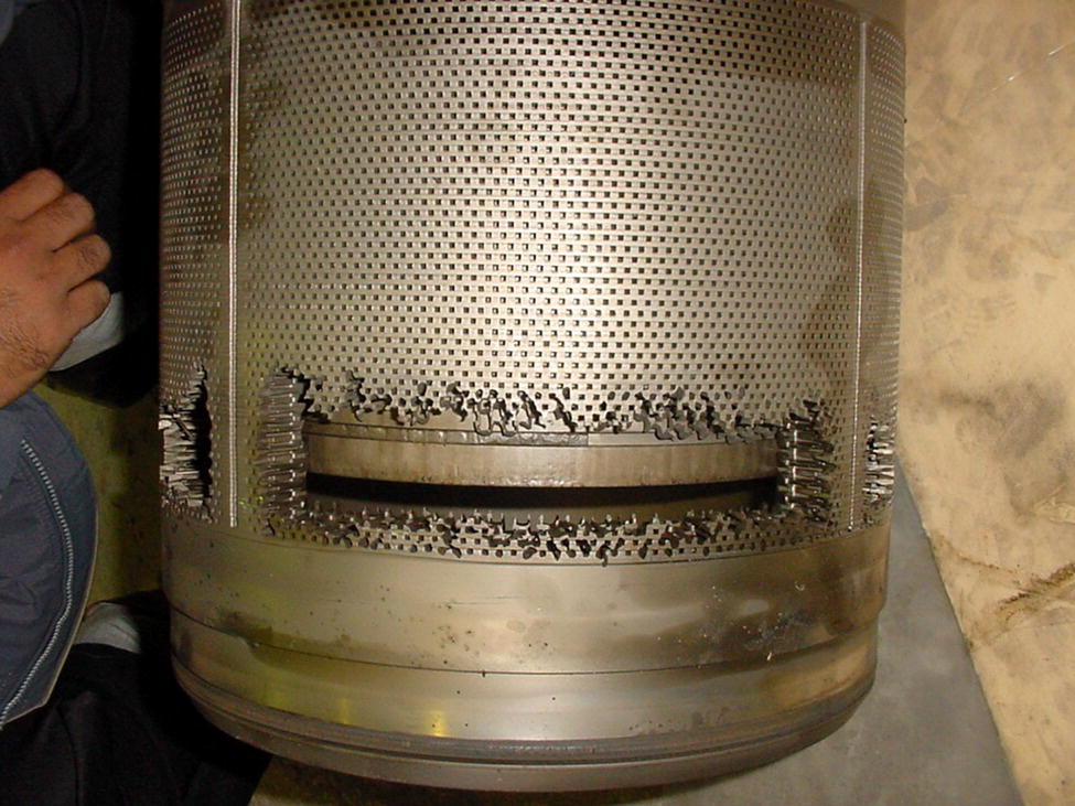
62.2 Impacts on Operations and Customers
62.3 Internal Corrosion of Sales Gas Transmission Pipelines
62.3.1 Sources of Moisture
62.3.1.1 Hydrotesting Practices
62.3.1.2 Condensation
61.4.3 Presence of Hygroscopic Salts on Pipeline Internal Surfaces
61.4.4 TEG Losses
62.3.1.3 Moisture Intrusion from Lateral Components
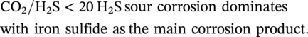
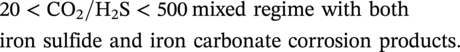
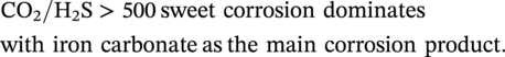
62.3.2 Formation Mechanisms
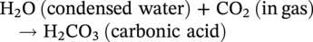
62.3.2.1 Siderite-FeCO3 (CO2 Corrosion)

62.3.2.2 Iron Sulfides (H2S Corrosion)


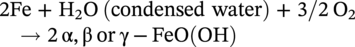
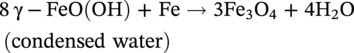
62.3.2.3 Iron Oxides (O2 Oxidation)
Constituent
Potential Sources
Fe3O4
α-FeOOH
Low dissolved oxygen-induced corrosion
Iron sulfides
H2S-induced corrosion
Siderite–FeCO3
CO2 corrosion
Elemental sulfur
Oxygen ingress leading to scavenging of H2S to elemental sulfur and water as per these reactions
2H2S + O2 ➞ 2H2O + 2S (elemental)
3FeS + 2O2 ➞ Fe3O4 + 3S (elemental)
62.3.3 Formation Rate
62.4 Analysis Techniques
62.4.1 Sample Collection
General Considerations
Specific Issues
Samples should be collected properly and consistently
Samples should be collected from the correct locations
Samples should be stored using proper procedures for subsequent laboratory analysis
62.4.2 Test Methods
62.4.2.1 Field Spot Tests
62.4.2.2 Laboratory Testing
Sampling Location
Total Suspended Solids g/MMSCF)
Size Range
<10 μm
<15 μm
<100 μm
A
12.60
75
93
98
B
1.84
46
70
95
62.5 Black Powder Movement
62.6 Erosive Properties of Black Powder
62.7 Black Powder Management Methods
62.7.1 Removal Strategies
62.7.1.1 Pipeline Cleaning1
57.4.2.2 Mechanical Cleaning
57.4.2.3 Chemical Cleaning
57.5 Pipeline Cleanliness
Method
Value/Applications
Dry/mechanical cleaning
Chemical cleaning
62.7.1.2 Black Powder Capture Methods
57.5.2 Cyclone Separators
Separation Technology
Value/Applications
Cyclones
Cartridge filters
Cyclo-filters
Magnetic separators
Wringing separators
57.5.3 Filters
57.5.3.1 Cyclo-Filters
57.5.3.2 Magnetic Separators
Wringing Separators
62.7.2 Prevention Strategy
62.7.2.1 Moisture Control
57.5.4.1 Proper Commissioning Practices
57.5.4.2 Gas Dehydration Process
62.7.2.2 Control of Corrosive Gases
62.7.2.3 Internal Coatings2
62.8 Monitoring Black Powder
62.9 Guidance on Handling and Disposal of Black Powder
Radionuclide
Exemption Level (Bq/g)
Lead-210
0.2
Polonium-210
0.2
62.9.1 Worker Protection and Contamination Control
62.9.1.1 Worker Protection
62.9.1.2 Contamination Control
62.10 Solutions
62.11 Summary
Acknowledgments
References
Notes