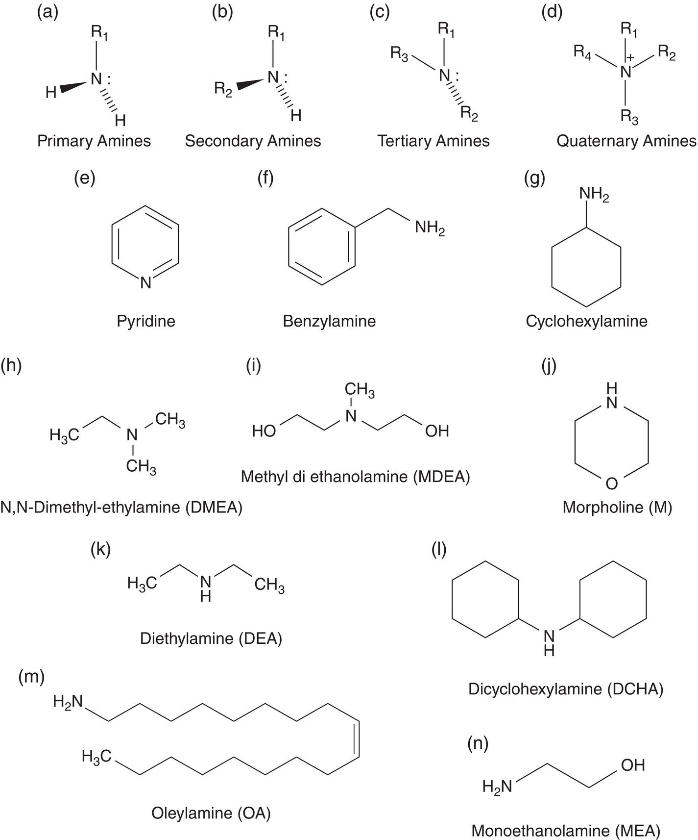
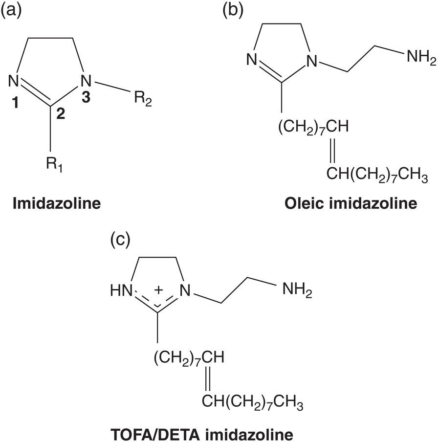
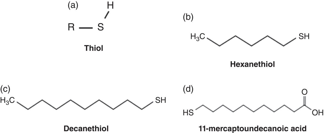
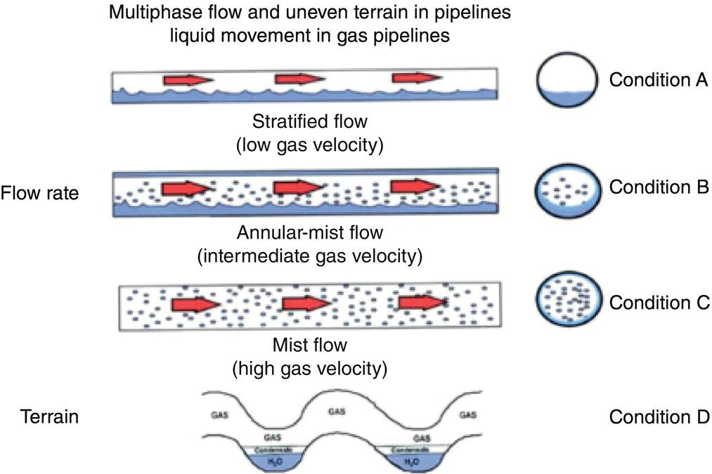
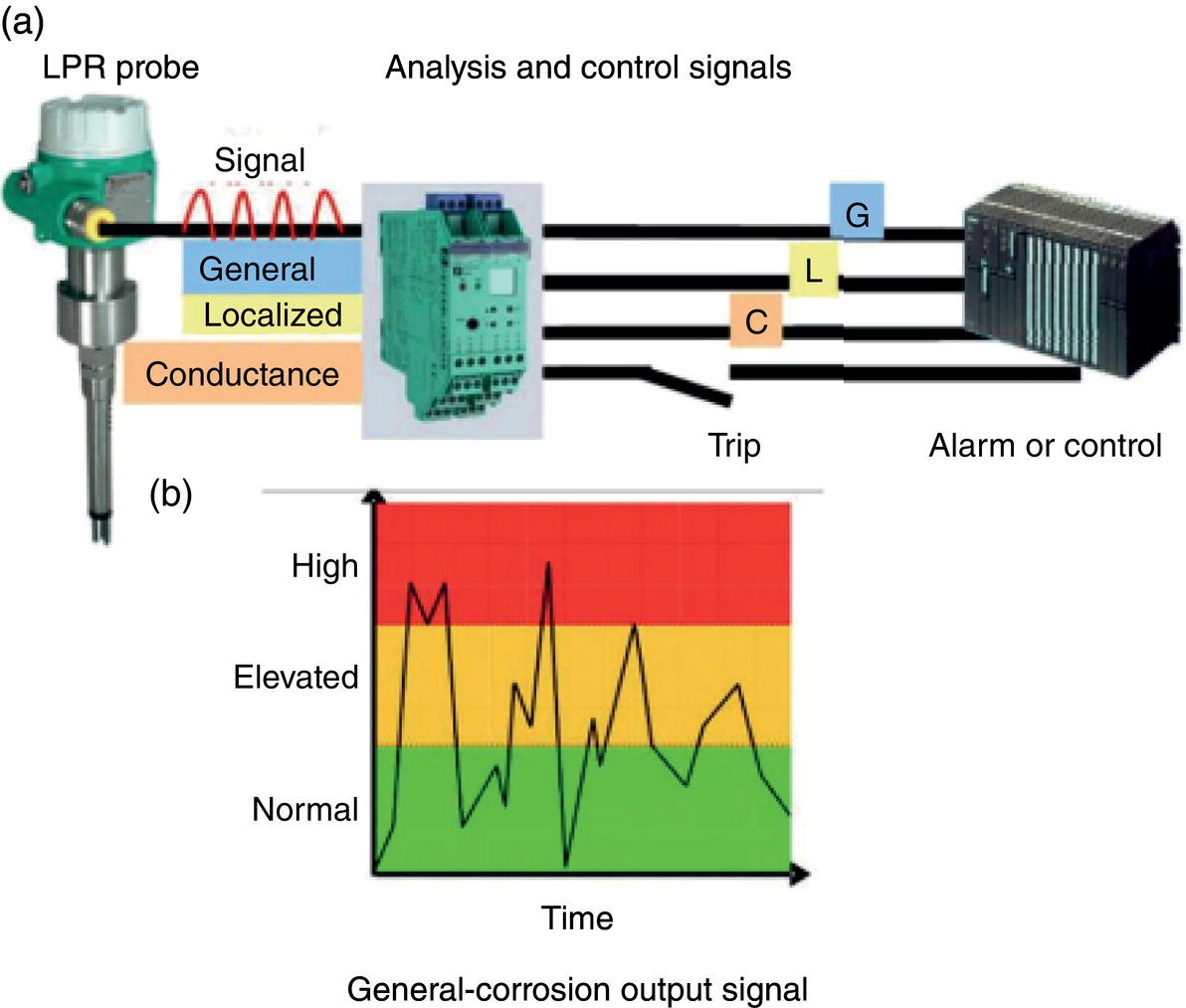
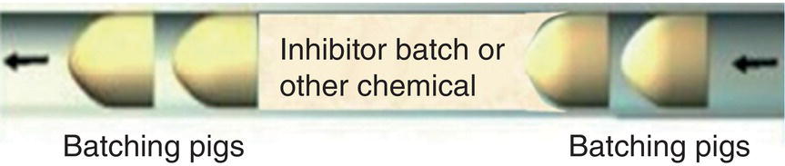
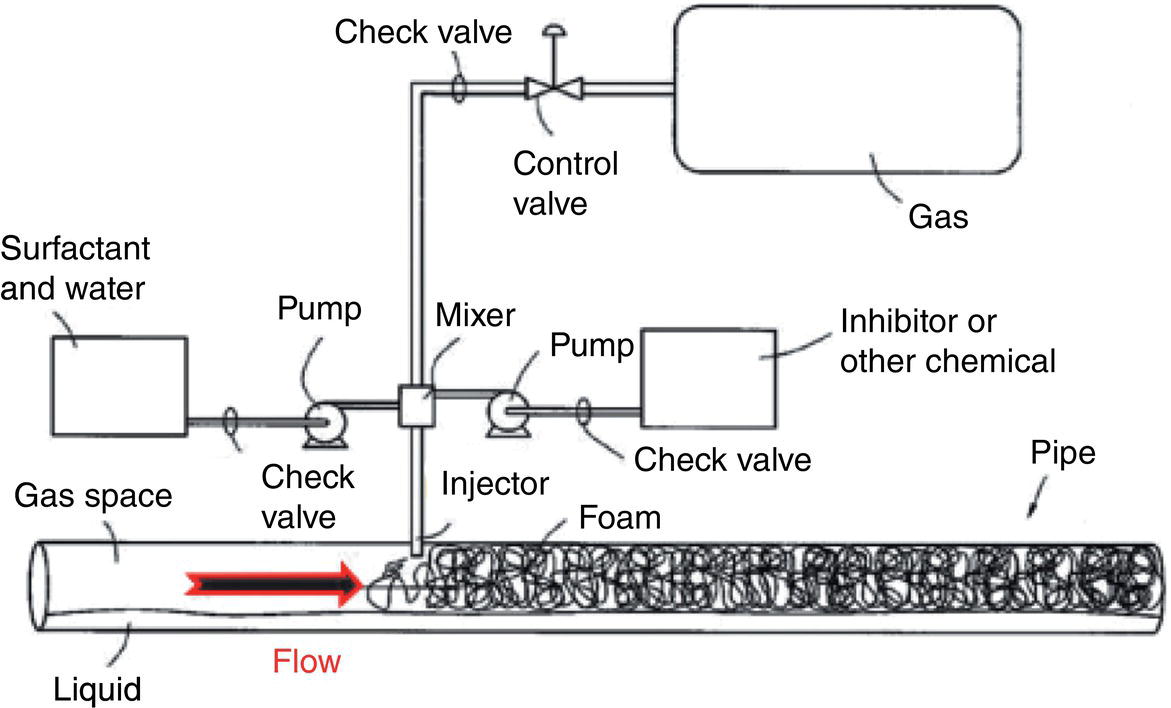
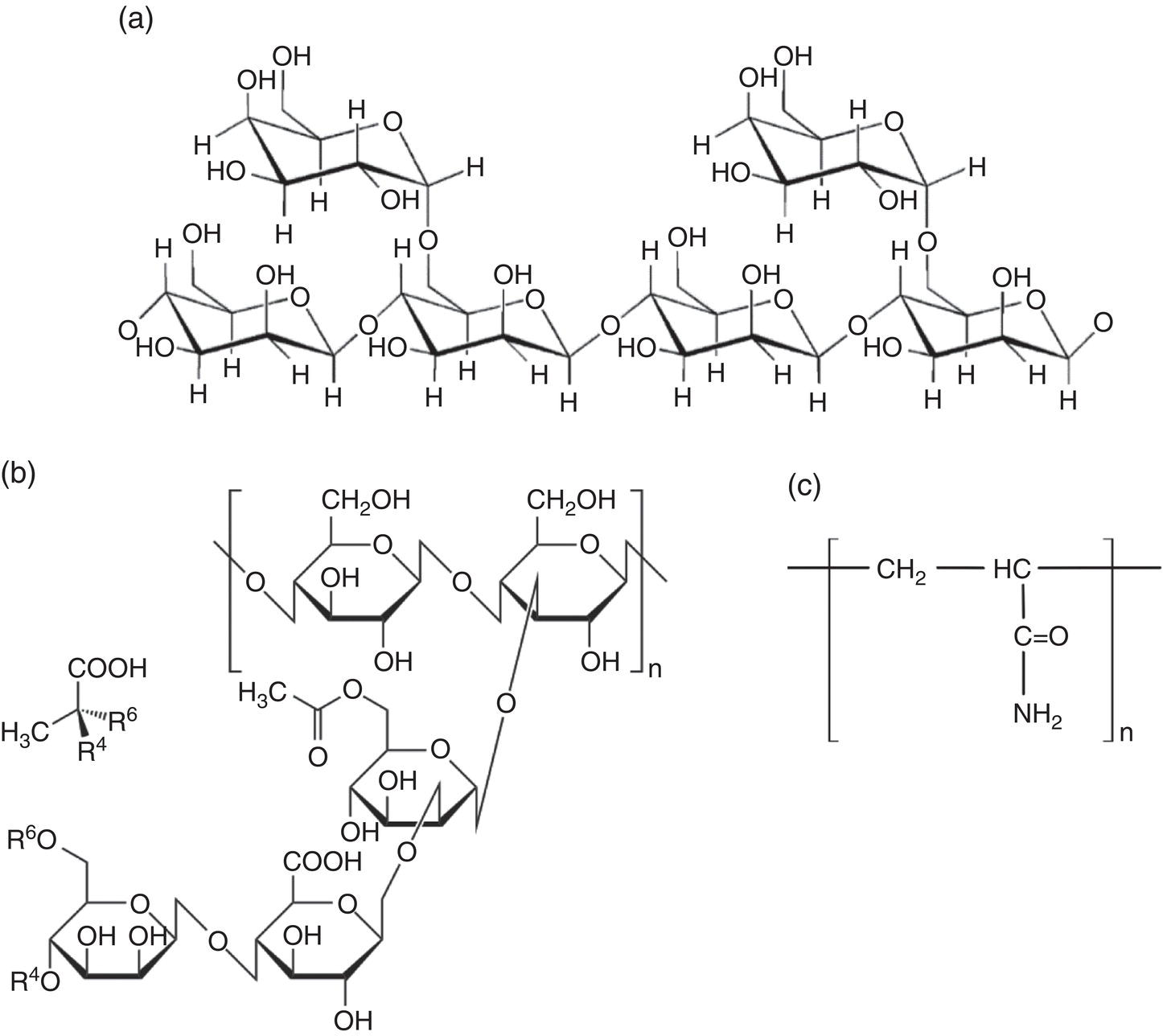
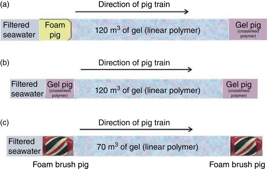
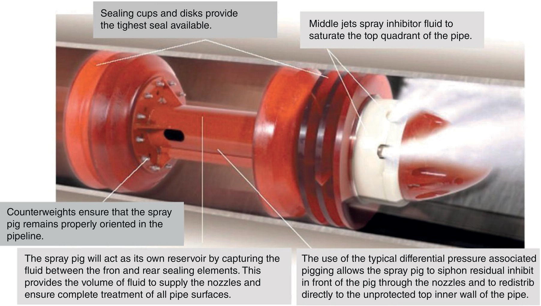
Aisha H. Al-Moubaraki1 and Ime Bassey Obot2 1Chemistry Department, Faculty of Science–Alfaisaliah Campus, University of Jeddah, Jeddah, Saudi Arabia 2Interdisciplinary Research Center for Advanced Materials, King Fahd University of Petroleum and Minerals, Dhahran, Saudi Arabia Controlling Top of the Line Corrosion (TLC) is particularly challenging. Traditionally, film-forming inhibitors and pH stabilization have been used as internal pipeline corrosion reduction techniques (using batch or continuous application). It is also possible to employ a corrosion allowance or an additional thickness of steel. Additionally, the use of specific alloys helps lessen metal loss from corrosion. However, TLC treatment using traditional corrosion inhibitors is ineffective because the stratified flow regime of TLC prevents the inhibitor present in the liquid phase from coming into contact with the surface of the top of the line pipe. Despite studies conducted in the lab and on the field, there are still challenges in TLC inhibition in multiphase natural gas pipelines. Most TLC research studies are still in the laboratory and screening stages, where the best corrosion inhibition formulations and transport methods for the inhibitors to the upper wall are being determined in order to stop the electrochemical reaction of condensed water at the metal surface. The fluctuating nature of TLC has a significant impact on the effectiveness of corrosion inhibitors used to protect it. This fluctuation refers to the tendency of the corrosion to change rapidly and unpredictably, especially for the worse. Additionally, the low pH of freshly condensed and the high temperature and pressure create severe conditions that need a strong interaction between the inhibitor molecule and the metal surface. In this chapter, we will provide an extensive explanation of the protection of oil and gas pipelines from TLC using inhibitors, the most important types used, and the application methods for inhibitors in TLC conditions. To prevent internal pipe corrosion due to TLC, it is the usual practice for carbon steel pipelines carrying CO2/H2S-containing wet gas to be dried before transport [1]. However, due to the high cost of dehydration, the oil and gas industry has adopted the widespread practice of using corrosion inhibitors. Corrosion inhibitors are chemicals that, when applied in small quantities to an environment, slow down the environment’s rate of attack without materially altering the concentration of corrosive species [2, 3]. It has been determined that a variety of factors, including interactions between the inhibitor and the metal surface, incorporation of the inhibitor on the surface layer, rate of chemical reactions at the metal interface, electrode potentials of the metal, inhibitor concentration, electrolyte pH, amount of dissolved oxygen, temperature, hydrodynamic conditions, and presence of aggressive anions, are responsible for the protective nature of the inhibitors on metal surfaces. By simply blocking the active sites on the metal surface, the anodic or cathodic reaction rate can be reduced, or the potential of the metal surface can be increased, allowing the metal to reach the passivation area, which encourages the creation of protective films on metal surfaces. When it comes to preventing internal corrosion in carbon steel pipes used to transport oil products, organic corrosion inhibitors are the most effective. It is a difficult undertaking to choose a corrosion inhibitor for a certain oil field. The organic chemicals such as amines, imidazoles, ammonium quaternary salts, and their derivatives containing 𝑁, 𝑆, and 𝑂 atoms or multiple bonds, which adsorb or interact with the metal surface to generate an adsorption film, have been found to be the most effective corrosion inhibitors in oilfield production [4]. Any inhibitor used in the oilfield must be highly effective at inhibiting corrosion, economical to produce, and compatible with other chemicals like scale inhibitors and biocides. All inhibitors used in the oil and gas industry must comply with environmental and safety laws in order to maintain safe working environments due to new operating regulations [5]. The production fluid’s oil/gas/water ratio determines the type of inhibitor to use, such as water-soluble, water-dispersible, or oil-soluble [6]. The injected inhibitor is scattered inside the pipeline at high gas flow rates as a dispersed spray, and as the droplet moves along the line with the gas flow, it reacts with the metal surface to form a protective film. Although the industry places a high priority on selecting effective inhibitors, it is more crucial that the inhibitor be applied effectively in order to reach the metal surface and offer the greatest amount of protection. Most inhibitors are capable of effectively preventing CO2/H2S corrosion on the inner wall of the pipe in wet conditions, even when the water phase is present at the bottom of the line. However, because the inhibitor cannot reach the pipe’s upper surface, TLC develops. To prevent electrochemical corrosion at the upper wall surface, the oil and gas industry needs to create a novel mechanistic way to transport corrosion inhibitors to the top of the line. While the volatility of corrosion inhibitors can impact their effectiveness in protecting against TLC, it is one of several factors contributing to their overall performance. Due to their capacity to create a self-replenishing barrier layer to safeguard pipelines, vapor/volatile corrosion inhibitors (VCIs) have been utilized to protect steel from a variety of corrosive pollutants, including moisture, condensation, oxygen, carbon dioxide, and hydrogen sulfide, as evidenced by numerous studies [7–9]. In certain applications, VCIs have been a key component in the protection of pipelines, oil and gas wells, refinery units, fuels, and multiphase flow systems [10]. Given the presence of organic acids, CO2, and H2S in the gas stream, which co-condense in the pipe’s upper wall, it is crucial for the VCI used for TLC to be effective not only against various corrosive pollutants but also in acidic conditions. This highlights the importance of selecting inhibitors that perform well under these specific conditions [11]. Regardless of whether it is solid or liquid, a VCI exhibits volatile characteristics at normal temperature. VCI is a combination of chemical substances that vaporize gradually. Gas vapor interacts with the metal surface, condenses, is hydrolyzed by moisture, and then releases ions that prevent metal corrosion. The volatility of these compounds has a substantial impact on their ability to suppress TLC because quick protective action requires high volatility, whereas lasting protection requires low volatility [12]. The concept of VCIs is not new. In the packaging sector, they have already been employed [11, 13–15]. Amine-based inhibitors, imidazoline-based inhibitors, thiol-based inhibitors, and a few more substances such as monoethylene glycol (alcohol), azoles, and aldehydes are the most prevalent VCIs being employed in TLC research. Their ability to prevent corrosion is highly influenced by a number of variables, including their chemical components, the environment in which they exist, the conditions in which they operate, and the characteristics of the metal surface [16]. Corrosion inhibitors should have the following characteristics when used in TLC applications [11]: Amines are compounds that are analogs of ammonia (NH3), in which either one, two, or three hydrogen atoms of ammonia are substituted by a substituent such as an alkyl or aryl group. Amines can be classified as either aromatic or aliphatic, depending on how many aryl groups are attached. The general formula of aliphatic amines is shown in Figure 63.1a–d. Two electrons are present in the nitrogen of the amine, and these electrons are drawn to the polar metal surface. The remainder of the molecule (alkyl groups) becomes extremely hydrophobic when it is attached to the metal, repelling water and severely reducing corrosion. Most aliphatic amines are less expensive and less harmful, and many are safe and are natural ingredients in foods and medicines. The production and purification of crude oil and natural gas use a variety of amines as operating materials; for example, alkanolamines are used in sour gas treatment facilities as absorbents and corrosion inhibitors [17]. In general, it seems that amine-type substances are the most often reported TLC inhibitors. Comprehensive research studies were successfully implemented to determine and test the effectiveness of volatile amine compounds as inhibitors for TLC [13, 18–29]. Different amine compounds have been tested based on their physical–chemical characteristics. Figure 63.1e–n shows the structure of some volatile amine inhibitors investigated as possible TLC corrosion inhibitors. The laboratory results indicated that the volatile amine compounds had good inhibition characteristics for TLC. Some of these research studies are presented below as examples. Oehler [22] investigated 16 generic amine VCIs for TLC inhibition. To determine how well these chemicals inhibited TLC, various assays were used. According to the findings of the study, compounds should have low molecular weight and boiling point, while having a high volatility for adequate TLC inhibition. Ramachandran et al. [26] reported the findings of a laboratory study of the inhibition of TLC by various volatile amine corrosion inhibitors, including morpholine (M), diethylamine (DEA), monoethanolamine (MEA), and a proprietary corrosion inhibitor (CI), under simulated TLC conditions. The results showed that whereas DEA and MEA have little to no effect on water condensation and TLC corrosion, morpholine (M) and the proprietary corrosion inhibitor (CI) considerably affect the water condensation rate and therefore show good TLC protection. Ajayi [28] investigated the efficacy of methyldiethanolamine (MDEA) and dicyclohexylamine (DCHA) as TLC inhibitors using various methods. According to the results, adding MDEA to wet gas significantly reduces corrosion rates (by up to 50 h), which functions as a pH stabilizer and promotes the production of FeCO3 films. The results obtained indicated that DCHA had effective TLC-inhibitory properties. The levels of polarization resistance gradually increased over time, which suggested that corrosion was becoming less of an issue. MDEA and DCHA were found to be excellent corrosion inhibitors for carbon steel in brine solutions containing CO2 gas at 60 °C for TLC, according to the findings of this study. Figure 63.1 Chemical structures of some TLC inhibitors based on amines. Despite the numerous studies that have been conducted using volatile amines as corrosion inhibitors for TLC, there still remain some research gaps. For instance, only low carbon steels have been investigated, while the use of volatile amines as TLC corrosion inhibitors for Cr-type alloyed steels is rarely studied. It should also be noted that utilizing amines at high concentrations (>500 ppm) was the only way to achieve low corrosion rates and high inhibition efficiency. Despite the fact that amines have been used successfully in a range of solutions, including deionized water, NaCl, and brine solutions with and without acetic acid (HAc), these solutions are regarded as low aggressive because they have low quantities of dissolved solid particles. The reported inhibitory efficiency may or may not be repeatable in extremely aggressive situations. Additionally, the amines have not been thoroughly studied in settings of actual hydrodynamic turbulence. One of the most common types of film-forming organic corrosion inhibitors is based on imidazoline chemistry. Two nitrogen atoms are present in the 5-atom heterocyclic ring of imidazoline [30]. The structure of imidazoline is divided into three substructures, as shown in Figure 63.2a. The long hydrocarbon chains (R1) create hydrophobic layers in the solution, which prevent corrosive particles from interacting with the metal. In general, oxygen, nitrogen, and other heteroatoms make up the pendant side chain with an active functional group (R2), which results in stable adsorption on the surface [31]. Several studies have been conducted using imidazoline compounds as corrosion inhibitors for TLC under different experimental conditions such as high temperature, high pressure, stagnant, and flowing using various mechanical methods [25, 32–39]. Notably, several of these studies have utilized a foam matrix to transport the corrosion inhibitor, enhancing its volatility and effectiveness in mitigation of TLC [25, 34–37]. The results of these studies have proven the efficiency of imidazoline compounds as corrosion inhibitors for TLC. Figure 63.2b and c shows the structure of the imidazoline compounds investigated for TLC. Some of the studies using imidazolines as TLC corrosion inhibitors are presented below. Figure 63.2 Chemical structures of some TLC inhibitors based on imidazolines. Jevremović et al. [34, 35] adopted a cutting-edge concept to investigate imidazoline-based formulation as TLC corrosion inhibitors. The corrosion inhibitor was injected into a foam medium as part of this innovative concept. A novel experimental glass cell design was used to assess the efficacy of the tall oil diethylenetriamine imidazoline (TOFA/DETA imidazoline) within the foam matrix. Treatment of the foam with a TOFA/DETA imidazoline on a periodic basis greatly reduced the TLC rate of carbon steel. This study demonstrated that TLC batch inhibition may be applied using a foam matrix containing TOFA/DETA imidazoline. It is important to note that the presence of the foam matrix is essential for the inhibition of TLC using TOFA/DETA imidazoline; without the foam, corrosion inhibition may not be as effective. In yet another study, Jevremović et al. [25, 36] utilized the same unique approach in a large-scale flow loop following successful laboratory trials to reduce TLC. The study found that regular application of foam having a high concentration of TOFA/DETA imidazoline corrosion inhibitors effectively reduced the TLC rate of carbon steel (Figure 63.2c). The inhibitory impact persisted between 3 and 15 h; however, the effect was not long-lasting. The entrainment and deposition of liquid droplets in a gas phase were examined in a study by Jauseau et al. [38, 39] as a potential means of conveying a nonvolatile corrosion inhibitor to the top of the line. The corrosion inhibitor utilized in this work was selected because it has previously been shown to be effective against bottom of the line corrosion (BLC); it comprised a 24% TOFA/DETA imidazoline-based inhibitor. This study concluded that droplet entrainment might be used to effectively limit the corrosion experimentation in a high-temperature, high-pressure, and large-scale flow loop of CO2-TLC. Like amine-based inhibitors, the use of imidazolines has been extensively researched for some forms of carbon steels. However, little work has been done to further explore the effects of these inhibitors on other types of steel, such as Cr-typed alloyed steel, that are also crucial to the gas and oil industry. In addition, the literature focuses on just one or two imidazoline derivatives. Therefore, it will be important to create additional varieties of imidazoline that could be effective for different types of steels. A thiol or thiol derivative is any chemical molecule with the formula R-SH, where R denotes an alkyl or other organic substituent (Figure 63.3a), and the -SH functional group can either be a sulfanyl group or a thiol group. Thiols are utilized as odorants to aid in the detection of natural gas, which has no odor when it is in its purest form. Thiols are also referred to as mercaptans [40, 41]. An S-H bond is moderately polar because there is only a modest difference between the electronegativity of sulfur and hydrogen. O-H bonds in hydroxyl groups, on the other hand, are more polar. Thiol dipole moments are smaller than those of comparable alcohols. Fe, Hg, Zn, Cd, As, Pb, Au, Ag, and Cu are strongly attracted to thiols, especially long-chain alkanethiols [42]. Thiol compounds have been discovered to be effective inhibitors of metal corrosion in a variety of conditions [42–46]. A few research studies have been conducted on the role of thiol compounds as inhibitors of TLC [47, 48]. The results of these studies have shown the high efficacy of these compounds as inhibitors through adsorption on the metal surface. Figure 63.3b–d shows the structure of thiol compounds used in these research studies. More intensive studies should be further conducted to provide insights on the mechanism of thiol compounds in inhibiting TLC. Decanethiol, hexanethiol, and 11-mercaptoundecanoic acid have all been tested for their ability to suppress CO2 corrosion using various methods [47]. The outcomes point to the formation of an adsorbed inhibitor film. To evaluate the residence time, additional tests were conducted. Among the studied inhibitors, decanethiol showed very good inhibitory properties and high persistence. The 11-mercaptoundecanoic acid and decanethiol provided superior protection against TLC than hexanethiol at the same applied concentration (100 ppmv). The effect of the operating parameters on the efficiency of decanethiol (Figure 63.3c) in TLC was examined by Belarbi et al. [48]. The impact of H2S, monoethylene glycol (MEG), and water condensation rates were also evaluated. At all tested gas temperatures and water condensation rates, the results obtained showed that decanethiol could protect the steel samples subjected to TLC conditions. With the chemical formula (CH2OH)2, monoethylene glycol (MEG) is an odorless, sweet-tasting, colorless, and viscous substance. Due to its employment in solid–gas hydrate prevention in wet natural gas pipes at low operating temperatures, such as sea lines, MEG is frequently referred to as a hydrate inhibitor [49]. When the CO2 partial pressure is very low, MEG has reportedly been employed as a CO2 corrosion inhibitor. However, it is important to note that MEG requires a concentration of more than 50 wt% to be effective as a corrosion inhibitor [50]. At increased CO2 partial pressure, however, corrosion control techniques such the use of pH stabilization would be necessary [51]. Because the rich MEG that was first injected into the flowline can undergo “reclamation,” which is a process of eliminating solids (non-volatile salts) that are collected in the formation water; the use of MEG is cost-effective [49]. The ability of steel to interact with the corrosive environment is hindered by MEG, which can adsorb on the steel surface [52]. MEG can decrease the solubility of Fe ions, which in turn causes the solution to become saturated with regards to FeCO3, slowing down corrosion [53, 54]. According to reports, MEG can slow down the pace of condensation in the TLC situation by lowering the vapor pressure of the liquid phase of the wet gas [52, 53]. Because most of the research was done under bottom of the line (BLC) settings, the effects of MEG on the TLC have not been sufficiently investigated. Condensation rate measurements were employed [52] to assess the inhibitory effect of MEG on the TLC since the rate at which water condenses is dependent on the temperature and MEG concentration in the bulk liquid. The solubility of FeCO3 was reduced, and the production of a protective layer increased by the higher MEG content. According to the results of this investigation, 90% MEG is enough to prevent TLC by lowering the condensation rate below the threshold of 0.25 g/m2s. Figure 63.3 Chemical structures of some TLC inhibitors based on thiols. Ajayi [28] investigated the effects of MEG on the TLC of carbon steel when HAc was present. According to the report of the study, MEG partially offsets the effects of HAc. MEG might therefore function as a kinetic inhibitor, delaying the formation of gas hydrates and thus slowing down corrosion in production pipelines [55]. The study assumed that MEG at the top of the line decreased the partial pressure of water by adsorbing it from the gas phase, lowering the dewpoint of the gas, and thus reducing the condensation rate and, as a result, the TLC rate. To investigate how MEG affects TLC, a glycol/water co-condensation model was created [56, 57]. The TLC rate and localized corrosion appeared to be inhibited by MEG, according to long-term experimental results. The effects of MEG on the condensation rate and MEG concentration in the condensing phase are what caused the corrosion outcomes. The effect of MEG on the TLC rate of low carbon steel in an acidic environment at high temperature was investigated in a study by Widyanto and Wiguna [58]. The TLC rate was significantly lowered after the addition of MEG to the HAc solution at 50 and 70 °C. The decreased rate of condensation led to a decrease in the production of the electrolyte required for the corrosion reaction. The MEG buildup, which results in another inhibitory mechanism, was confirmed by the rising MEG inhibition impact during the experiment. However, it is important to note that this effect is not significant unless the MEG content in the bulk liquid phase is higher than 70 wt% [50]. The effects of gravity, flow rates, and stratified flow make transportation of corrosion inhibitors to the sites of TLC challenging. Inhibitors with foam or gel, continuous injection through atomization, batch treatments using a persistent film of inhibitor between two pigs with the addition of pH neutralizers/hydrate preventers, and slug treatment with or without diluents have all been used to control internal corrosion of wet and multiphase gas gathering or transmission pipelines over the years [59, 60]. The traditional inhibitory techniques, which have been shown to be effective for protecting against BLC corrosion, such as continuous or intermittent/batch injection, slug-or continuous treatment, do not necessarily provide much protection from TLC. To achieve greater pipeline protection, it is generally desirable to combine at least two approaches for the efficient delivery of inhibitors to the entire pipeline [61]. While most conventional corrosion inhibitors are known to have varying durations of effectiveness, it is always a good idea to reapply a fresh inhibitor to keep the inhibition program effective. The persistency of these inhibitors can vary depending on the type of the inhibitor and the coating system used [59, 62]. For inhibition, a proper surface preparation is required. In particular for batch treatments, mechanical or chemical cleaning procedures should be used to remove internal scale so that the inhibitor film adheres adequately to the pipeline surface [63]. The effectiveness and persistence of the corrosion film on the surface are also impacted by the fluid flow pattern. It is also important to study the compatibilities and/or interference between the corrosion inhibitor formulations. Administering inhibitors or other treatment chemicals at the site can be facilitated by locating a reservoir of the chemical at the wellhead or at a convenient point along the pipeline, such as a pumping station. The treatment chemical can then be introduced into the flow stream using a pump of suitable size or by employing an educator pump to extract the chemicals from the reservoir. Complete, 360-degree coverage is achievable, provided there is sufficient turbulence to distribute the chemicals. However, this method can present several challenges, particularly as chemical and flow conditions may differ between injection stations, which are typically located downstream of pumps (see Figure 63.4) [61]. Figure 63.4 Multiphase flows and terrain in gas pipelines. (Reference [61]/Society of Petroleum Engineers/Public Domain). Wang et al. [64] suggest that certain pipeline conditions, such as slug flow, can lead to the formation of bubbles in the line. This can interfere with the formation of a complete inhibitor film, potentially leaving areas of the pipeline unprotected. This is particularly relevant in turbulent flow conditions. Kaul [65] demonstrated that the effectiveness of inhibitors can vary depending on the flow conditions within the pipeline. In full-pipe flow, inhibitors can be highly effective, often nearing 100% effectiveness. However, in slug flow conditions, the effectiveness of inhibitors can be significantly reduced, often falling below 50%. It is important to note that these percentages are not absolute and can vary based on specific conditions and inhibitor types. Unwanted chemical interactions can generate additional issues during treatment fluid injection. In a manufacturing train, the application of corrosion and scale inhibitors has been discussed by Gonzalez et al. [66]. They pointed out that it is frequently necessary to inject several chemicals sequentially or concurrently at relatively close injection locations, such as anti-scale and anti-corrosion additives. As a result, it is important to check for chemical incompatibilities and/or interference as well as to assess the effectiveness of each chemical separately. The anti-scale efficiency, anti-corrosion efficiency, or both additive efficiencies may be impacted by these interferences. The scale and corrosion that were seen in previous pipeline failures despite the use of significant amounts of both chemicals may have been caused by this type of mutual decline in efficiency. A corrosion probe (or other sensor) can frequently be programmed to start the introduction of an inhibitor automatically when a set point is reached and to stop it once the desired effect has been achieved. Automated monitoring and corrosion-control systems are built around electronic corrosion probes. This automation can ensure a more efficient and continuous injection of CI, which is crucial for maintaining the integrity of the pipeline. According to Szabo et al. [67], as part of an extensive plantwide management approach, many of the expenses directly associated with corrosion may be reduced and managed via continuously monitored corrosion transmitters. The impact of electrochemical corrosion on process parameters can be reduced by using immediate, continuous corrosion feedback for active control and neutralizer tuning (e.g., inhibitors). The system described in this study uses an LPR probe that measures fluid conductance and general corrosion (Figure 63.5a). The signals are transmitted to a data analyzer, which decodes them and sends the data to an alarm/control unit. Figure 63.5b shows an illustration of a corrosion-rate output signal. The system may be designed to start the injection systems automatically, or the signals may notify the operator to activate the flow of the corrosion inhibitor. The flow conditions must be suitable to transfer a nonvolatile inhibitor to the top of the line in order to control the TLC. Introducing a variety of chemical additives into the flow stream is considered to enhance TLC inhibition. This is particularly useful in challenging flow conditions where achieving a thorough distribution of chemicals to the highest point of the pipeline can be unpredictable due to fluctuating pipeline conditions. However, it is important to note that the effectiveness of this approach can vary and is dependent on specific pipeline conditions and the types of additives used. Figure 63.5 Automated corrosion monitoring and alarm/control system. (Reference [61]/with permission of Society of Petroleum Engineers.) The issue of volatility is being addressed by various authors because most inhibitor formulations are made to remain in the liquid phase. Inhibitors that evaporate from the flowing aqueous phase at the bottom of the line are one strategy for preventing TLC. These inhibitors, often referred to as vapor-phase inhibitors (VPIs) or vapor corrosion inhibitors (VCIs), can also be present in a more typical inhibitor formulation. As a result, VPIs or VCIs designed to be volatile in flowing conditions may serve as protection for the vapor-space pipes. In many pipeline environments, continuous injections are often the preferred and practical method for treating corrosion. However, in certain cases, such as in wet gas lines with stratified flow, where continuous injection may be physically or economically impractical, batching could be considered an alternative option. For top of the line treatments, the line segment must be fully or partially filled in order to contact all the surfaces. An oil-based fill fluid in an aqueous phase that has enough inhibitors to contact and coat all surfaces is acceptable. To calculate batching intervals for corrosion inhibitors and for some of the methods discussed in this chapter, online monitoring using the techniques shown in Figure 63.5 may be necessary. Additionally, specific equipment is needed for evaluating TLC and inhibition [61]. Different kinds of pigs can be used by operators to aid in coating a pipeline interior. As stated in Pruett [68], one way to apply a treatment liquid to the inside of a pipeline is to capture it between two pipeline pigs (referred to as batch pigs) that move alongside each other while carrying the treatment liquid. The upper quadrant of a pipeline interior may not always be fully coated with or exposed to the treatment liquid, despite the fact that this procedure is commonly accepted and practiced. This is comparable to the fluid-filled pig train depicted in Figure 63.6. A sufficient amount of inhibitors must be applied to the pipeline as one way to guarantee coverage. The surface area of the line can be used to estimate the total amount of inhibitors required. In order for the slug of inhibitor to coat the top of the line, the pig train must move so that all surfaces are contacted. The contact time required for effective inhibition may vary based on specific inhibitor formulations and pipeline conditions and should be determined based on experimental data or industry standards. The efficiency of the inhibitor may be impacted by the presence of a hydrocarbon liquid in the line, as reported by Van Gelder et al. [69], who advise that a 5% solution of the inhibitor in oil should contact pipe surfaces for at least 10 seconds. The inhibitor molecules can move, adsorb, and perhaps even react with the metal and/or a corrosion scale throughout the contact duration. Figure 63.6 Slug between pigs. (Reference [61]/with permission of Society of Petroleum Engineers.) According to Bojes et al. [70] and Menendez et al. [71], batch corrosion inhibitors are commonly employed for the corrosion control of production wells and pipelines in the oil and gas industry. Based on the authors, guidelines that take film thickness, contact time, and surface area into account are still frequently employed to determine the volume of batch inhibitors needed for pipeline applications. But by really evaluating the thickness of the inhibitor film on the metal and the effects of many factors (such as the type of inhibitor, contact time, diluents, dilution ratio, and shear stress), it may be possible to improve the application process and necessary batch frequency. The inhibitors evaluated had viscosities ranging from 4 to 18 cp, and the investigators claim that the percent coverage was more essential than the thickness as a predictor of longevity of corrosion protection during shear (rotating-cage) test conditions. Any TLC inhibitor needs to have its persistence optimized in order to offer the greatest amount of protection. Selection of corrosion inhibitors and other additives is based on several factors. These include the nature of the corrosion process, the specific fluid phase that requires inhibition, the target area within the pipeline, and the mechanism employed for replenishing the inhibitor film. An emerging technology area is the use of inhibitors added to chemical gels or foams as TLC reduction treatments. The capacity of these thickened fluids to cover a complete pipeline segment with a higher-viscosity fluid (than an unmodified liquid) may boost the film persistency. These modified fluids are used in numerous oilfield production processes [72] and industrial cleaning operations [73]. To prevent corrosion between treatments, the inhibitor formulation in either scenario must be compatible with the foam or gel and then adsorb onto the metal surfaces. In pipelines, a foam phase can form, and other treatment chemicals, including corrosion inhibitors, can be added and employed to coat every surface of the pipeline. A liquid source, a gas (often a hydrocarbon gas, N2, or CO2), and a surfactant that is compatible with the liquid phase are required for foams that are employed in pipelines or process-vessel cleaning treatments in order to stabilize the foam [74]. Gases are coarsely dispersed in a little volume of liquid to form foams. In oilfield terminology, foam’s “quality” is denoted by the following [73]: where Vl represents the volume of the liquid and Vg represents the volume of the gas. The total represents the foam’s volume. The range of foam quality is thought to be 52–95%. When the percentage reaches over 95%, the foam often transforms into a mist with gas as the continuous phase. Because there are no bubble–bubble interactions to provide resistance to flow or to gravity separation at less than about 52%, stable foam does not exist. The gas concentration is high enough when the foam quality is over 52% for the bubble surfaces to touch. In manufacturing operations, fluids with a quality of less than 90% are usually referred to as energized fluids, and fluids with a quality of 90–95% are called foams. It should be noted that if the fluid volumes and flow rates are known, the same equation (Equation 63.1) may be used to compute the foam quality with a liquid or gas flow rate. It is clear from Equation (63.1) and Karam [75] that foam can take up significantly more space than an equivalent mass of liquid. Shear in a foaming device is one of the various ways that foams can be produced. A water/surfactant (or hydrocarbon/surfactant) is mixed with another fluid, such as an acid or concentrated corrosion inhibitor, and then with the gas phase in the straightforward configuration shown in Figure 63.7. Different aqueous-fluid foams and hydrocarbons require different surfactants. Foam can be created by introducing a gas into a liquid flow straight in the pipeline if there is sufficient shear. The proposed use of foams created in pipelines to control TLC corrosion is described by Achour et al. [76, 77]. The corrosion inhibitor, according to them, is supposed to be injected into a foam matrix. The produced gas creates a foam slug that travels around the pipeline, contacting the pipe’s full circle for a certain distance. If the foam does not break naturally, according to these authors, it can be broken with a defoamer before separation. This procedure ensures that the inhibitor is delivered uniformly to the pipe wall along TLC-affected pipe sections. This procedure is said to be more cost-effective than the traditional techniques of treating TLC with pigging or batch inhibition because it does not stop or delay production. For a summary of the foaming agents and corrosion inhibitors that these authors investigated for their paper and patent application, see Table 63.1. Figure 63.7 Foaming setup for gas, liquid, and chemical injection. (Reference [76]/ConocoPhillips Co/Public Domain). Table 63.1 Foaming Agents and Corrosion Inhibitors Source: Reference [76]/ConocoPhillips Co/Public Domain. In the process of applying inhibitor chemicals to pipeline surfaces, chemically gelled water or oil are often utilized. The use of foams for this purpose is less common, whereas gels, also referred to as “gelly pigs,” have a well-established history in pipeline operations, including the application of inhibitors. One of the advantages of gels is their ability to be pumped through any pipeline that is designed to handle liquid, despite their highly viscous nature. In liquid lines, gel pigs can be employed alone, in place of batching pigs, or in combination with several kinds of traditional pigs. Gelled pigs can increase performance when utilized with traditional pigs while virtually minimizing the possibility of sticking a pig. Gel pigs do not lose their effectiveness in use like regular pigs do (though they can degrade from shear). However, keep in mind that the fluids can be gas reduced and diluted. Therefore, while building a pig train that includes gel pigs, care must be taken to limit fluid bypass of the pigs. When displacing with gas, a traditional pig should be placed at the back of the train [61]. Additionally, according to this source, gel pigs have been employed to momentarily close valves during hydrotesting. Figure 63.8 shows the chemical structures of guar, xanthan, and polyacrylamide used as gels. Either the gel pig or the gel can have inhibitors or perhaps other substances added to them. The most crucial concept is that the inhibitors must be examined to determine whether they can be transported via the pipeline and whether they will work with the gel. A full-line segment and the pressure necessary to move the “train” are needed for gel applications. Three ideas for using different pigs are shown in Figure 63.9 for consideration. In this diagram, (1) shows mechanical pigs, (2) shows inhibitor applications without solid pigs, and (3) shows solid pigs with some cleaning capability. These setups can be combined in any way [78]. Kennard and McNulty [79] claim that inhibitors and biocides can be deposited using gels. The gels’ high viscosity will promote and facilitate spreading treatment chemicals throughout the full surface of the line. To ensure compatibility with the treatment being used, the gels can either be manufactured from aqueous brines or from oil. Numerous inhibitors can be included in formulations of gelled oil. Gels (and foams) should be used if the line is particularly challenging to pig with mechanical instruments. There are benefits even in lines that can be pigged [61]. Several characteristics of fluids will help in inhibitor placement, according to Quarini and Shire’s study [80] of the usage of different types of pigs, including gel pigs. These characteristics include Figure 63.8 Gel chemicals: (a) guar, (b) xanthan, and (c) polyacrylamide. (Reference [61]/Society of Petroleum Engineers/Public Domain). Figure 63.9 Pig train options. (Reference [78]/with permission of Society of Petroleum Engineers.) While foams and gels may have certain uses for enhancing surface contact with surfaces that need to be blocked, they must be “broken” at the end of the run. Additionally, prolonged contact with the surfaces or the inclusion of breakers [61] may be required to enable fluid disposal. If a line is piggable, issues with contacting all of the line’s surfaces can be resolved by using a specialist pig. The Bernoulli (or Venturi) effect is applied to a specially built spray-producing pig, which uses the energy of bypass flow to do the work required to redeploy and redistribute leftover inhibitor chemicals throughout the pipe run. Pruett [68] and Freeman and Williamson [81] describe this alternative method. TLC has been tackled successfully by reusing or efficiently moving corrosion chemicals in pooled accumulations along the bottom of the pipeline as an alternative to “chemical batching.” The design of this device is shown in Figure 63.10. The authors pointed out that when continuous injection is the main method of supplying corrosion-inhibitor fluid into the pipeline, there is one way to use the spray pig. This approach works best on pipelines with a continual upgrade and reasonably flat lines, like those connected to offshore wells. While distributing fluids containing inhibitors to the top of the line, the spray pig has shown to be a very efficient dewatering pig. In this way, as the pig splashes through and jets the liquids, a thick vapor cloud is produced in front of it. Figure 63.10 The V-Jet® spray pig system. (Reference [61]/with permission of Society of Petroleum Engineers). Freeman and Williamson [82] describe the use of a semiautomated spray-pig system for treating TLC in order to get performance data. This system is identical to the one in Figure 63.10. Engineers have integrated various inline inspection technologies into the body of the pig itself as an onboard data recorder to close this gap and provide more instantaneous feedback on the performance of a spray pig in any specific application. Basically, it is a spray pig with a “brain.” According to the inventor, the device can function under typical spray-pig circumstances, and the pig is set up to gather a variety of data throughout each run. This contains information on differential pressure (ΔP), which is crucial for getting the right jetting action. Pressure is measured at the pig’s front and back by the semi-intelligent spray pig. A spray pig must deliver inhibitors to the top of the pipe for it to be effective. The semi-smart design also keeps track of the pig’s rotation and position to confirm that this is truly taking place. A complete 3D profile of the pig’s motion throughout the run is provided by the data collected by the device, which also include information on tool rotation, spray-nozzle orientation, and port orientation. The pig’s sensors can determine whether an erroneous orientation was temporary or permanent and where it occurred in the pipeline if it does occur (for example, relative to known corrosion areas). Additionally, as reported by Freeman and Williamson [81], the separator system works best when utilized in a “train” with a spray pig that contains an inhibitor and a foam pig that completes the application. Figure 63.11 illustrates a crucial element of applying an inhibitor successfully to all metallic line surfaces. In order to allow the inhibitor coating to reach the metal surface and offer long-term protection, it is demonstrated how to use a scraper pig to help remove part of the surface scale. If at all possible, a cleaning phase should come before applying any inhibitors. Figure 63.11 Spray pig with train of additional devices. (Reference [61]/Society of Petroleum Engineers/Public Domain.) Table 63.2 Comparison of Application Methods for Pipeline TLC Corrosion Inhibitors Source: Reference [61]/ConocoPhillips Co/Public domain. The advantages and known drawbacks of the application approaches discussed in this chapter are compared in Table 63.2. Different approaches can be required by various line configurations (piggable or nonpiggable) [61]. The decision may also be influenced by the amount of liquids and gases in the line and the shear conditions.
63
Mitigating Top of the Line Corrosion (TLC) Using Corrosion Inhibitors: Types and Application Methods
63.1 Introduction
63.2 Inhibitors Used to Mitigate TLC
63.2.1 Amine-Based Inhibitors
63.2.2 Imidazoline-Based Inhibitors
63.2.3 Thiol-Based Inhibitors
63.2.4 Monoethylene Glycol-Based Inhibitors
63.3 Application Methods for Corrosion Inhibitors Under TLC Conditions
63.3.1 Continuous or Periodic Injection of Inhibitors into the Flow Stream
63.3.2 Conventional Batch Treatments with or Without Pigs
63.3.3 Inhibitor Application with Foams or Gels
63.3.3.1 Foams as Inhibitor Carriers
Foaming Agent
Corrosion Inhibitor
N-decyl-N-dimethylamine oxide
3-methoxyproplamine
Dodecyl aminodipropionate
3-Methoxyproplamine bromide
Sodium C14-16 olefin sulfonate
Didicyldium ethyl ammonium bromide
Dodecylbenzene sulfonic acid
Decylamine caprylate
Dendritic polymer (DP foamer)
Corsicana® Dodecylbenzene Octylamine caprylate
Glucopon 215 UP
Cyclohexylamine caprylate
63.3.3.2 Gelled Fluids as Carriers for Corrosion Inhibitors
63.3.4 Applications of Inhibitors with Specialty Pigs

Methods of Application
Benefits
Disadvantages
Commercial status
Reference
Injection of contemporary inhibitors
Uses current equipment and systems, used on line.
Dispersion and top of the line contact dependent on line turbulence.
Commercial
[83]
Injection of advanced inhibitors
Uses current equipment and systems, on line and pigs not needed.
Film life and complete surface coverage are not proven.
Research phase
[1]
Batch treatments with slugs and pigs
Many years of experience and histories
Distribution and top of the line contact depend on line turbulence; extra inhibitors may be needed. The line must be off-line and piggable.
Commercial
[70]
Foams
Uses less liquid, fills all parts of the line, and may be used on line.
Film life has not been proven, distribution is dependent on line turbulence, and top of the line contact.
Development phase
[76]
Gels
Excellent surface contact can be used with pigs for cleaning.
Downside of any pig treatment is off-line; with pigs.
Commercial
[84]
Spray pigs
Excellent surface coverage; uses less inhibitor for coverage.
Line must be piggable when off-line.
Commercial
[81]
Spray pig with 2-step inhibitor
Excellent surface coverage; long film life.
Line must be piggable when off-line.
Development phase
[85]
63.3.5 Comparison of Inhibitor-Application Methods
References
