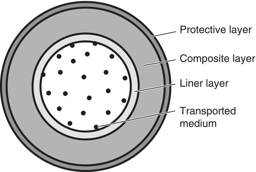
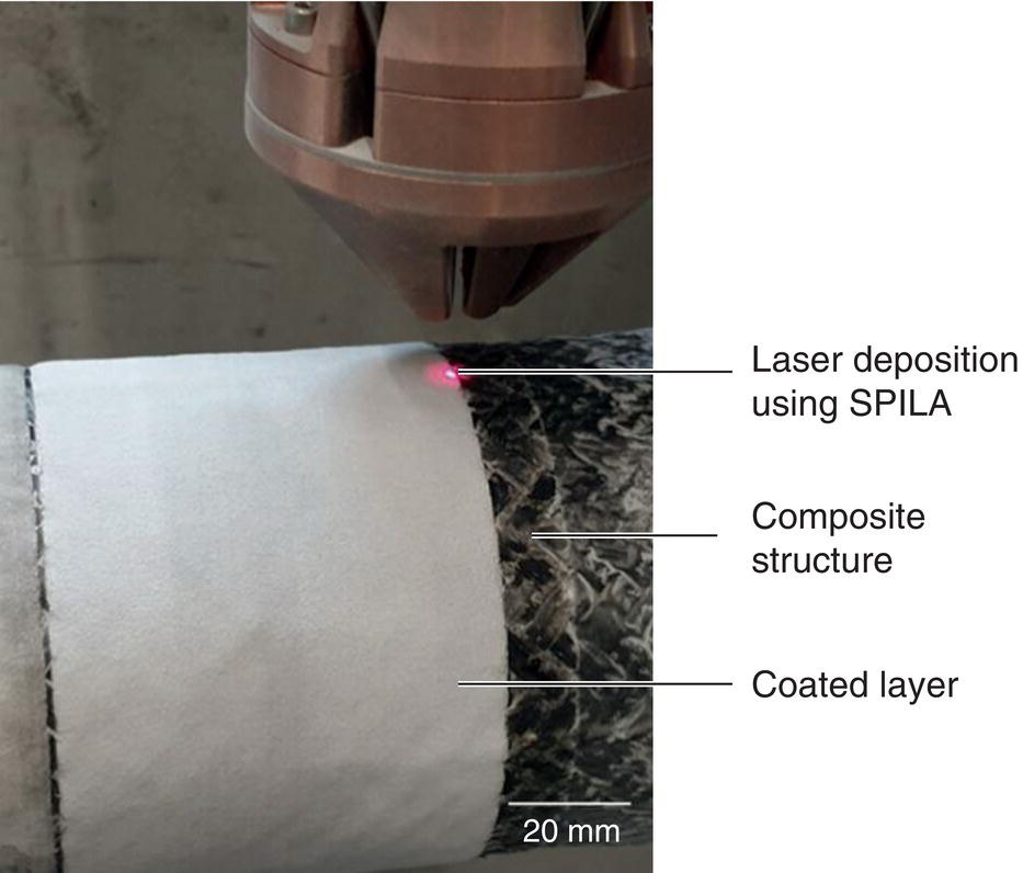
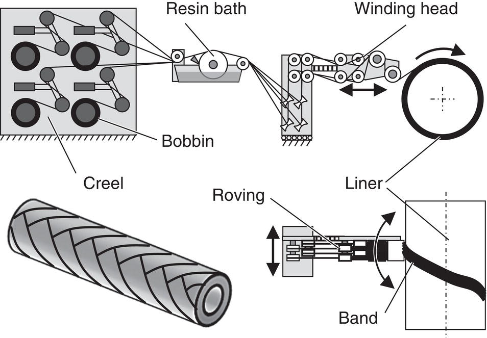
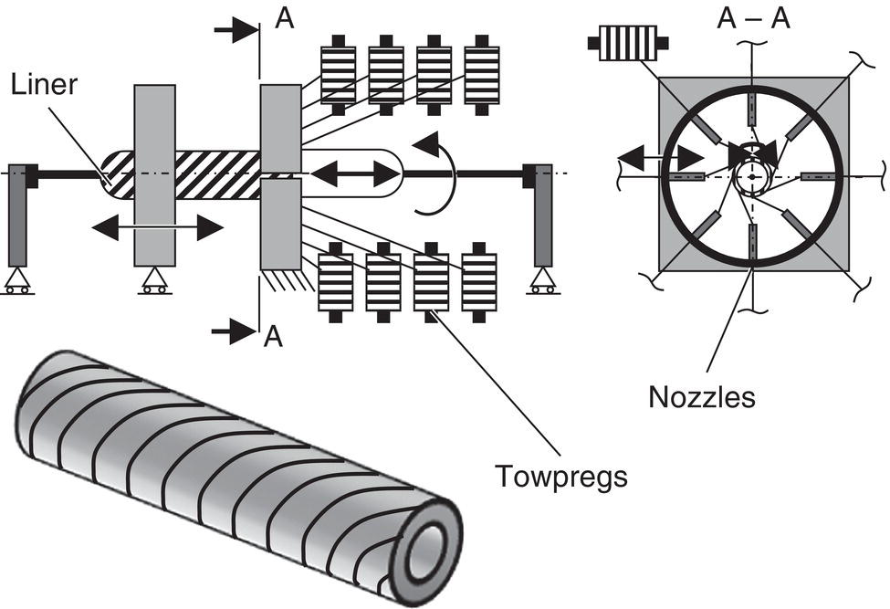
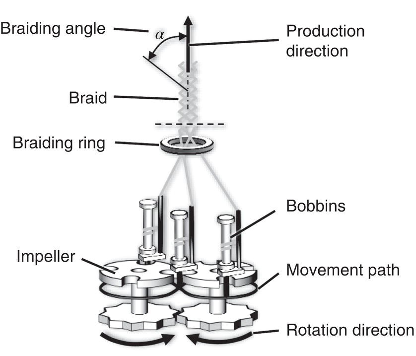
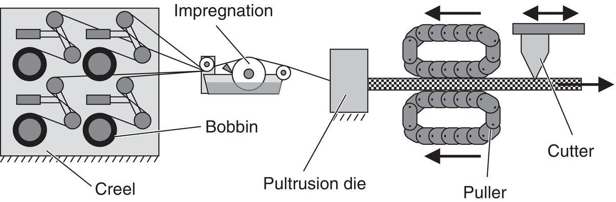
Niels Grigat, Stephan Koß, Ben Vollbrecht, Tim Mölling, Johannes Henrich Schleifenbaum and Thomas Gries Institut für Textiltechnik, RWTH Aachen University, Aachen, Germany Since industrialization, the transport of energy sources has presented mankind with major challenges in terms of efficiency, durability, and environmental compatibility. Conventional oil and gas pipelines were made of metallic materials. However, due to technological and material developments over the last few decades, nonmetallic composite pipelines are increasingly being used for the transportation of oil and gas. Relevant applications include onshore and offshore pipelines, tubular storage facilities, and downhole pipes. The advantages of nonmetallic composite pipelines include corrosion resistance, lightweight construction due to high specific strength, flexibility, and adaptability. In the context of increasing energy demand and growing awareness of environmental protection, the need for pipelines that can withstand harsh conditions while minimizing environmental impact is paramount. This chapter provides an overview of the material choices, possible designs, process techniques, and applications of nonmetallic pipelines [1–3]. The choice of material for pipelines depends on the type of media to be transported, the environment, the loads, costs, and legal guidelines. In the oil and gas industry, a distinction is made between metal-based and composite-based materials [4–6]. Metallic pipelines have a comparatively simple structure. In addition to the metallic steel pipe, an internal and/or external coating of epoxy resin, zinc, or alternative corrosion-inhibiting materials is usually applied. Depending on how aggressive the medium to be transported is, an inexpensive carbon steel or an alloy steel is chosen. With stainless steel, for example, improved corrosion resistance is achieved by adding chromium and nickel. Nonmetallic composite pipelines have a wide range of materials, which can range from metal–plastic combinations to pure plastic pipelines. If the composite pipelines consist of a relevant metallic component, they are referred to as hybrid pipelines. This versatility of possible material combinations contributes to the aforementioned increasing use of nonmetallic composite pipelines. Composites are generally defined as a material mix of two or more components, combined to improve mechanical, chemical, or physical properties. Fiber-reinforced plastics (FRP) are composite materials made up of polymer matrices and a reinforcing fiber material. FRP provide excellent strength and stiffness properties while ensuring lightweight design. As FRP consist of two main components, the fiber and the matrix, every constituent is performing a distinct task. Thereby, the fibers provide a beneficial tensile stiffness and strength, while the matrix maintains the fibers in position, protects against environmental influences, and transfers outer loads toward the fibers [7]. Commonly used reinforcing fibers in FRP are carbon, glass, aramid, and natural fibers. Depending on the fiber orientation and fiber fraction, the material properties can be designed according to the desired requirements of the application. Fibers may be cut into discrete lengths or be used as continuous filaments, depending on the manufacturing process. Additionally, chopped filaments are distinguished by length into short and long fibers. One of the most convenient forms for multifilaments is the roving, which is also used for the production of pipelines. Rovings, also referred to as tows, are a strand of untwisted continuous filaments. However, twisted multifilaments are referred to as yarns. In the following, an overview of various textile structures by the processing of rovings is illustrated. For two-dimensional fiber forms, the three main structures are weaves, noncrimped fabrics, and nonwovens. In Figure 15.1, an overview of one- and two-dimensional fiber forms is illustrated [7–9]. Figure 15.1 Definition of one- and two-dimensional fiber forms. ([8], 2011 / with permission of Springer Nature.) For polymeric matrix material, a differentiation between thermosetting and thermoplastic polymers is made. Typical polymers for thermoplastics are polyethylene (PE), polypropylene (PP), or polyamide (PA). These thermoplastic resins are cross-linked and thereby can be repeatedly melted and reused. The deformability due to elevated temperatures provides advantages in terms of processability. Thus, the operating temperature of thermoplastics is fairly limited. Further, this matrix type is prone to moisture absorption. On this occasion, the expansion due to absorption can lead to additional internal stresses [7, 10]. In contrast to thermoplastics, thermosetting polymers cure irreversibly. By mixing the two components, hardener and catalyst, the solidification process is induced. Consequently, thermosets are distinguished between three different stages. Thereby, the A-stage describes a state of liquid gel in which the resin is fully soluble and fusible. If the resin is partially cured, the state is referred to as B-stage. Due to a state below the gel point, the processability of the B-stage is enhanced. On this account, B-stage resins are used for prepregs. Finally, the C-stage defines a fully cured resin. The most commonly spread thermosetting resins are epoxy and polyurethane. Since thermosets are better suited for elevated temperatures, these resins are widely used in FRP production. Due to the close covalent compound, the cured matrix provides greater strength compared to thermoplastics [7, 10]. Various textile manufacturing technologies are capable of processing hybrid materials that feature both fibers and resin, omitting additional production steps such as impregnation. Typically, such hybrid materials provide additional advantages such as a controlled fiber volume fraction or elevated processing speeds. In the form of rovings, three main types of hybrid materials are distinguished, which mainly differ in the form of the resin component: commingled yarns, thermoplastic tapes, and towpregs. Commingled yarns consist of reinforcing filaments and thermoplastic filaments, which are broadly mixed by commingling. Thermoplastic tapes are rovings preimpregnated with thermoplastics and shaped into a form of tape with distinct width and thickness. Towpregs are also preimpregnated rovings; however, the term “towpregs” refers to thermosetting matrices. For towpregs, the storage time is limited as the reaction of the resin is slowed down but cannot be fully stopped [7, 8]. The manufacturing of nonmetallic composite pipelines consists of the production of the following basic layers (see Figure 15.2): Figure 15.2 Design of a basic nonmetallic composite pipeline. (Niels Grigat.) The liner produced in the first step is required on the one hand as a base body for the composite layer to be applied. On the other hand, the smooth inner surface ensures that the fluid to be transported can be transported with a low coefficient of friction and low losses. The choice of liner (e.g., HDPE or PA11) can also serve as a permeation barrier, particularly for easily permeating gases such as hydrogen [11]. Besides the mentioned basic layers of nonmetallic composite shown in Figure 15.2, further layers may be added for specific applications. Such layers can be a tensile armor, carbon pressure armor, or a steel carcass [4] for an increased ring stiffness, or additional materials, such as aluminum foil layers as a permeation barrier. Another option for coating pipelines is the deposition welding process. This process can be used to coat conventional steel pipelines, but with new processes such as the Separate Powder Injected Laser Application (SPILA), it can also be used to coat nonmetallic composite pipelines. Through the decoupling of the energy input from substrate and coating material, the use of SPILA makes it possible to coat FRP with metallic alloys (Figure 15.3). This way, the advantages of metallic surfaces and mechanical strengths of FRP can be combined and the range of possible applications significantly increased [12, 13]. Figure 15.3 Picture of coating on a composite structure (carbon fiber–reinforced plastic) by means of SPILA [12]. (Stephan Koß and Niels Grigat.) To reduce the thermal load on the FRP, low-melting alloys such as aluminum-based alloys are used to create a closed coating. The particle speed, the relative powder focus position, and the process speed are used to achieve a high energy input into the powder materials, so that as little energy as possible reaches the substrate surface. This allows a material bond to be created between the metallic coating and the FRP in the case of the use of thermoplastic base material. In the case of thermoset resins or plastics, the fibers must be exposed in advance so that the molten particles can create a mechanical bond with the fibers. The most relevant manufacturing processes for the textile composite structure of tubular reinforced composites are pultrusion, filament winding, tape laying, braiding, and centrifugal casting. In regard to the manufacturing of oil and gas pipelines, the process technologies of filament winding, braiding, and pultrusion are explained in detail in the following. Currently, filament winding is the most commonly used manufacturing approach for tubular composite structures. The general set up for filament winding consists of a mandrel that rotates around a spindle, which coincides with the mandrel’s rotational axis (Figure 15.4). Close to the mandrel, the delivery eye is moved on a carriage to feed the impregnated rovings of fiber reinforcement onto the mandrel’s surface under pretension. The carriage moves horizontally, parallel to the mandrel’s rotational axes with controlled speed. Before passed toward the delivery eye, the pretension is adjusted at a creel and multiple rovings are combined to a band. For wet filament winding, the dry rovings are passed through a resin bath for impregnation [14]. Figure 15.4 Schematic of the filament winding process. Another approach is the utilization of preimpregnated rovings, defined as towpregs. By eliminating the resin bath, towpregs allow higher processing speeds of up to 5 m/s and reduced resin content variation of approximately 2 wt% [15]. Alternatively, to classical filament winding, other winding approaches exist. In contrast to filament winding, the multisupply filament winding (MFW) process enables the simultaneous processing of many towpreg rovings (e.g., 48 or even more depending on the machine size) (Figure 15.5). For this purpose, the rovings are split in an equal distribution along hoop direction of the mandrel and fed through nozzles. The nozzles can move in radial direction, allowing to maintain a constant distance between liner and nozzle. Since the large number of rovings provides an increased surface coverage for each winding step, less winding cycles are required for the completion of a complete layer. Further, the winding of unidirectional layers for surface coverage of 100% is possible for moderate diameters and elevated fiber orientations toward hoop direction. Besides deploying multiple rovings simultaneously via the so-called helical unit, the hoop unit can additionally be used for the winding of hoop reinforcements. Since hoop reinforcements require only few rovings for full coverage, the utilization of this separate unit is useful for MFW [15, 16]. Figure 15.5 Schematic of the MFW process. (Adapted from [15].) Braiding is well-established in the industry for manufacturing tubular structures. Since a large number of rovings can be processed simultaneously, a beneficial productivity is achieved. Today, braids are utilized in various aerospace applications due to proficient mechanical properties. Since braids provide excellent damage tolerances and impact performance, these composites surpass metallic alloys in many ways. Basically, the process of braiding is illustrated in Figure 15.6. The bobbins move through impellers. As the process starts, each bobbin is carried for half a revolution and passed on the neighboring impeller. While one impeller is rotating clockwise, the neighboring impeller is turning counterclockwise. Thereby, a sinus movement is induced inside the machine. All rovings pass through a braiding ring and are braided onto a core, which is pulled or pushed. Accordingly, tubular cores are overbraided or reinforced, respectively. Additionally, stationary braiding threads can be added to manufacture triaxial braids. The stationary threads contribute to the stiffness in longitudinal direction of the braid, as they are simply braided in the direction of production (0°) [18]. Figure 15.6 Schematic of the braiding process. ([17] / with permission of Institut für Textiltechnik der RWTH Aachen University.) Braiding processes are distinguished between radial braiding and horizontal braiding. Horizontal braiding machines feature bobbins in axial direction. Due to major redirections of the rovings, fiber breakage can be induced. Therefore, a radial arrangement of the bobbins pointing toward the machine center induces minor redirections. Furthermore, suitable thread guiding elements and plates used in radial braiding improve this behavior [19]. Pultrusion, or strand drawing, is an established process that is widely used for the production of FRP profiles. The high degree of automation and continuous production enable cost-effective production of several 100 profile meters and more. At low volumes, the process is cost intensive due to the high equipment costs [8]. In principle, the structure of a pultrusion system can be divided into the following subsystems: material intake and feed, pultrusion tool, heating system, haul-off, and cutting device (Figure 15.7). The material intake on the left can take on a variety of arrangements, depending, among other things, on the type of semifinished products used. Usually, coils arranged in gates are used for the reinforcing fibers. Flat reinforcing materials such as nonwovens or fabrics are stored and fed on rolls. The feeding is done via guide rollers, which direct the reinforcing structures toward the impregnation device [20]. The difficulty here is to guide the individual fiber strands precisely into the die. Depending on the quantity of individual fiber strands and the complexity of the profile, several meters are required for this. The subsequent impregnation takes different forms depending on the process. A common method is the use of an impregnation bath through which the rovings are passed before entering the mold and impregnated with the resin contained. Resin infusion is another method in which the matrix material is injected into the mold under pressure, thus impregnating the reinforcing fibers in the mold [21]. The final shaping takes place in the mold. The impregnated fibers are heated by a heating system. The necessary temperature is determined by the resin system used. A combination of heating and cooling zones is often used to prevent premature reaction of the matrix or to ensure controlled curing of the profile. Thermoplastic matrix systems in particular require temperatures of over 200 °C to melt completely. By continuously narrowing the mold cross section to the final dimension, the matrix is distributed by the pressure increase and impregnates the reinforcing fibers. This results in high pressures, especially with thermoplastic matrices, due to the increased viscosity of the melted plastic. Finally, the takeoff must be mentioned. Depending on the profile and the required haul-off forces, caterpillar hoists, chain hoists, or hydraulic clamps are used here. In the final processing step, the continuously produced profile is cut to the desired length. The process chain can be extended as required, especially after cutting, which results in a further increase in the aforementioned automation capability [20]. In addition to the automation capability, the takeoff speed is decisive for the most cost-effective production possible. Speeds of 0.2–3.0 m/min can be achieved with thermoset resin systems. In contrast, speeds of up to 20 m/min are possible when thermoplastic matrix systems are used [20]. With the further development of the pultrusion process, the profiles that can be produced have also become significantly more complex. In case the radial braiding process or MFW process is used prior to the entry of the die, tubular structures such as pipelines can be processed via pultrusion [22]. Figure 15.7 Schematic of the pultrusion process. ([8], 2011 / with permission of Springer Nature.) The connection of nonmetallic pipelines must be designed in such a way that the manufactured nonmetallic composite pipeline can be connected to nonmetallic segments as well as to metallic segments and other system components. The connecting elements can be designed either as metal parts or nonmetal parts. If the connecting elements are made of metal, it should be noted that this is critical as it counteracts the advantage of corrosion-resistant nonmetallic pipelines. If so, the metal parts must be made of highly anticorrosive metal materials. Possible connection types are adhesive connections, laminated connections, mechanical plug-in connections, flange connections, couplings, and screw connections. The choice of connection depends largely on the pressure rating and the diameter of the oil and gas pipe [23]. The use of nonmetallic composite pipelines for the transportation of oil and gas can basically be divided into three categories: The design of the pipelines is very closely linked to the requirements in the three categories mentioned and also to the medium to be transported. A distinction is made here between liquids, such as oil, and gaseous media, such as natural gas. The nature of the medium also plays a role in the design of the pipeline system to be manufactured. In the case of onshore pipelines, a distinction is also made between distribution networks in the low-pressure range and transportation networks in the high-pressure range. The pressures in distribution networks are usually in the range of maximum p = 16 bar, so that fiber reinforcements can sometimes even be dispensed with to achieve the necessary mechanical strength. The lightweight design of nonmetallic composite pipelines simplifies installation processes, making them cost-effective and efficient for land-based projects. Their resistance to corrosion is particularly beneficial in onshore environments where soil conditions and climate variations can pose challenges to traditional metallic pipelines. The same corrosion resistance applies to offshore pipelines due to the aggressive salty sea water. Furthermore, the lightweight nature of nonmetallic composite pipelines reduces the load on downhole equipment, making them advantageous for enhanced oil recovery operations. The structural strength and durability of nonmetallic composites contribute to improved performance and longevity in downhole environments [24–26]. In summary, the application of nonmetallic composite pipelines in the oil and gas industry represents a transformational advance that addresses critical challenges and offers a sustainable alternative to traditional metallic pipelines. The choice of materials, primarily fiber-reinforced polymers, emphasizes the corrosion resistance, light weight, and high structural strength of the pipelines. The manufacturing methods, including innovative techniques such as filament winding, pultrusion, and braiding, ensure that the pipelines meet stringent industry standards for durability and reliability. These pipelines have a wide range of applications in onshore, offshore, and downhole environments. Their corrosion resistance makes them ideal for harsh environments and also for transporting fluids with a corrosive effect against steel such as hydrogen or gases with, for example, sulfur-containing impurities. The lightweight construction of nonmetallic composite pipelines simplifies installation and reduces overall project costs. From transporting hydrocarbons on offshore platforms to enhancing oil recovery in downhole operations, nonmetallic composite pipelines demonstrate versatility and adaptability. As the oil and gas industry continues to prioritize efficiency, longevity, and environmental sustainability, nonmetallic composite pipeline applications are emerging as a promising solution. The successful integration of advanced materials and manufacturing processes with a wide range of applications positions nonmetallic composite pipelines as a key contributor to the industry’s evolution toward safer, more reliable, and cost-effective transportation systems [2, 4].
15
Nonmetallic Composite Pipelines
15.1 Introduction
15.2 Materials
15.2.1 Composites

15.3 Manufacturing
15.3.1 Filament Winding
15.3.2 Braiding
15.3.3 Pultrusion
15.3.4 Joining Methods
15.4 Applications
15.5 Conclusion
References