Binder Singh1 and Ben Poblete2 1GGS, Houston, TX, USA 2Consultant, Houston, TX, USA This chapter will integrate the main areas for the successful design and pragmatic application of safe and efficient offshore pipelines and subsea assets to best practices and recognized regulatory systems. The main disciplines addressed are role of risk and corrosion within integrity management (IM); major accident events (MAEs) and corrosion phenomena; integration of risk and corrosion engineering practice; role of corrosion and reliability modeling; practical guidelines for corrosion in the context of hazard identification (HAZID), hazard and operability (HAZOP), failure mode effects and criticality analysis (FMECA), and as low as reasonably practicable (ALARP); development of pragmatic risk allocations (qualitative and quantitative); risk-based methodologies and technologies; risk and fit for life cycle solutions; case histories, corrosion lessons learned (LL), and context for regulations. In addition, the interpretation of risk, health, safety, and the environment (HSE); corrosion and IM; recommendations; and future strategies are also covered. Updated commentary with an emphasis on third-party peer review/verification (TPR/V) and new perspectives on LL, are included. Offshore (including subsea flowlines and near onshore pipelines) are a critical part of the oil and gas infrastructure. The range of design and operations extends from shallow water <200 ft (accessible by diver) through to medium depth up to 1000 ft (diver/remotely operated vehicle [ROV] access), deepwater 1000–7000 ft (needs ROV) through to ultradeepwater ≫7000 ft (nowadays exceeding 8000 ft), ideally with complex subsea campaigns. The environments are dangerous and very difficult to monitor or inspect. Worldwide surveys consistently show that the greatest threat to the integrity of upstream pipelines is corrosion; see Figure 68.1. Moreover, it is clear that the largest part of that is due to internal corrosion (typically >51%). More recent work has shown that most of this is due to localized corrosion of the main pipe body, although other surveys have shown that for topsides (marine atmospheres) significant leakage also occurs at flanges and connections. For high-risk systems, more than 80% of the IM process is effectively corrosion management. For lower corrosive risk systems, the corrosion component may be 30% or 50%, depending on the application. The inset in Figure 68.1 shows a graphic of the “Swiss cheese” effect, which basically postulates that final failure is usually the result of many undesirable events aligning at the same time (poor design, bad materials, risky operations, etc.), and that is certainly the case for corrosion failures as we will see later in this chapter. As a rule, we note that intervention after the event is nearly always identifiable. The challenge is to intervene before the accident event happens, and that is actually done quite frequently, but of course not so well advertised; and there is usually no glory in prevention! It is essential to get designs right with minimal intervention over the life cycle (typically 20–30 years). This means that for the deeper more complex cases, it is preferable and often “mandated” by the operators to use inherently safer designs (ISDs) with greater corrosion allowance (CA) if steel is to be used, or more likely the argument is made to use more corrosion and degradation resistant materials, such as corrosion-resistant alloys (CRAs). These may be used in solid form (very expensive) or in the clad form. For the latter, clad situation, the flowline is usually made of steel, such as API 5L X65 or X70 and so on, but it is internally weld clad or mechanically clad with a 3–4 mm thick internal CRA sleeve. This can be a cost-effective solution, although new problems can arise; for example, the CRA may lead to mixed material issues, alloy dilution, or galvanic corrosion at interfaces to carbon steel or individual susceptibilities to localized corrosion, such as pitting, crevice, or microbially influenced corrosion (MIC). Figure 68.1 Main failure modes for offshore pipelines in the upstream sector. A number of offshore/subsea failures, including MAEs, have been linked to corrosion; and in particular, the role of localized corrosion has been identified as an important, often latent, step. The principles of addressing this mode of failure can be assessed for all marine/subsea/offshore assets, including pipelines and risers. As a result, corrosion assessment and control, via a corrosion management strategy (CMS), may be considered the critical part of life cycle mechanical integrity, which may be equated to IM. “Fit for purpose” solutions must include an emphasis on a safety culture, application of existing knowledge, and LL. Most engineering codes, standards, and recommended practices provide only partial guidance to corrosion assessment and control; it is incumbent on designers and operators to utilize best industry knowledge and experience. In contrast, offshore/subsea seawater side or onshore soil side corrosion is well addressed by cathodic protection (CP) specifications and codes, and thus is generally very effectively “policed,” and problems usually only occur when code criteria are not met. Furthermore, retrofitting is often available to “top up” CP systems with extra sacrificial anodes or perhaps redesigned with hybrid (sacrificial plus impressed current) systems, tailored for each case under code guidance, such as ISO, DNV F103, or DNV RP B401. For those reasons, CP is not generally risk based unless the applications are outside the limits of the standards given. Nevertheless, defining greater sensitivities and margins of safety have become more important in the context of CP and coatings that are expected to perform at the high pressures, high temperatures, and high velocities (HP, HT, and HV) because of the greater reservoir depths and more sophisticated subsea technology required (greater stress on materials from outside [seawater side] as well as inside turbulence (hydrocarbon production side). Modern day CP, often deploys hybrid systems, i.e., Sacrificial and ICCPS combined to cater for complex systems, such as distributed sacrificial coatings under difficult geometries. Overall, it has been recognized that internal corrosion issues can be similar for all large- and small-diameter pipes. Recent high profile corrosion-related failures have shown how incorrect or mismanaged internal corrosion can lead to failure. The main challenges are considered misunderstanding of the severity of damage mechanisms, incomplete development of codes and standards, and a lack of appreciation of the near misses, which should not be overlooked as a prime source of data. Risk-based approaches are required to satisfy the fast track nature of deep offshore/subsea projects. Other challenges to deepwater CP designs are related to inappropriate deepwater cold anode chemistries (usually aluminum based with tightly prescribed indium, zinc, and iron contents), and designers should take great care to verify that the required performance can be met both by theory and by practical testing of the anode materials; see Figure 68.2 for examples. Figure 68.2 Typical “overactive” anode (left) and “overactive” TSA coating (right), both sometimes observed in deepwater applications, due to improper anode chemistry and possible underestimation of bare steel or inordinate amount of CRA in the subsea infrastructure. Overactive anodes can reflect rapid consumption even after 1–2 years, and the need for designers to accurately determine the surface area of seawater-wetted steel is crucial in the design calculations. The use of coatings must be supported with reliable coating breakdown factors (typically 2–10%) for most scenarios; information is usually given by most of the CP standards and recommended practices available. Other reasons for early deterioration of anodes and thermal spray aluminum (TSA) coatings may be connected to high dissolved oxygen in warmer subsea loop currents >5 ppm (rather than the expected <2 ppm at depth). Key performance indicators (KPIs) can be used to engage and make life somewhat easier for busy technicians, inspectors, and operational field staff. The accepted methodology now seems to favor a traffic light KPI interpretation, visually color coded (Table 68.1) so that operators are alerted to significant changes and do not miss any adverse trends in the potential data being accrued. More recent CP performance data have revealed the presence of onerous microbial corrosion activity even under ostensibly good CP; see Figure 68.3. Here, we show the stage-by-stage corrosion development of bare chain steel as metal dissolution is propagated. The same principles may be interpreted as possible degradation mechanisms for deep sea buried pipelines, in areas where microbes may thrive, perhaps without being impacted by CP. This approach may be described as corrosion risk prediction by analogy and is a very useful way forward for deep sea applications. So to recap, even in the confident world of good coatings and excellent CP standards, the advent of deep subsea exploration and HP/HT/HV criteria, there is much work to do in refining and readjusting the codes of practice to address the critical corrosion control issues. In practice, one new approach is the placing of anodes in clusters at various staging posts of subsea structures, PLETs, PLEMs/SCR riser bases, and so on. Here, the anode arrays are successful in propagating the CP current and protective potential along great distances, up to and beyond 25,000 ft with good coatings in place. The reader is directed to the many codes and standards (latest and post 2020 issues recommended since much revision has been underway) in that regard. Table 68.1 Color coded KPI bands depicting critical bands of potential, for bold surfaces (excludes shielded areas and crevice formers). Noting that −800 mV is still code compliant, but −820 mV is the suggested action point Figure 68.3 Microbial corrosion (sulfate-reducing bacteria and iron oxidizing bacteria) can corrode deepwater mooring chains even under code designed CP. This type of attack will apply to deep subsea pipelines by analogy. The use of third-party review and verification, TPR(V) has proved very useful in better assuring life cycle integrity for such safety critical items. Figure 68.4 Pipeline potential attenuation data depicting good agreement of annual CP pipeline survey against design and modeling trends between two anode clusters (typically 6–15 in total) usually quite tightly packed at each end. Figure 68.4 summarizes this aspect, showing how modeling design data and monitoring data confirm this trend and provide confidence in reliability for subsea pipeline corrosion control. The corrosion challenges faced by the offshore industry are considerable. For example, note the size of the spar facility under tow, compared to the coastal buildings in Figure 68.5. Observe the density of anodes dotted around the structure and the strakes designed to quell motion induced vortices. More recent R&D studies prompted by Industry have demonstrated the validity of equidistant holes within the strake sleeves to ensure good CP distribution under the sleeves. This is made possible by the vast amount of experience accumulated with coatings and CP monitoring as well as retrofit possibilities if indeed deemed to be required, and many subsea assets have been so retrofitted often with hybrid CP systems based on a mixture of sacrificial and impressed current systems. The reader may look into that since most of the work is now in the public domain. In addition, some useful internet links are provided in the References and Bibliography sections at the end of this chapter. Figure 68.5 Offshore spar under tow to field location; note vast array of evenly spaced sacrificial anodes welded to the structure. Observe strakes designed to stabilize against sea state motions and vortices. All offshore assets, such as the spar shown in Figure 68.5, are connected to horizontal subsea pipelines via vertical pipe risers; thus the corrosion control, CP, and coating systems must be compatible. Subsea pipelines corrode excessively if the structure CP system is “under” designed. Hence, pipeline corrosion engineers must ensure compatibility of the two CP systems or ensure isolation of the two systems. That isolation must be assured over the full life cycle, and that is usually verified at least biannually by taking separate survey CP potential measurements simultaneously on the structure and the pipeline or riser. The principles of corrosion/CP codes and standards can be applied to all configurations, whether structures, pipelines, pressure vessels, piping, and so on. Regarding risk-based solutions, the important point is always to observe and not violate the principles such as the basic thermodynamics (what can happen) and the essential kinetics (what will probably happen). In contrast, if risk assessments are applied in contravention to such fundamentals, then they will not succeed, an important point to remember when assigning personnel of the correct competency level in both risk and corrosion. Figure 68.6 Adapted I–P–F curve interpreted for localized corrosion, emphasizing need for responses (solutions) when corrosion initiated, for best measurable and thus actionable KPIs. The remainder of this chapter will concentrate on the more difficult subject of internal corrosion and other corrosion challenges not so well code driven. In that regard, and in reality, many corrosion mechanisms are understood relevant, but not always applied for realistic prediction; typically, such analyses focus on uniform corrosion, which can be effectively modeled; and various software (private, JIP, public domain, etc.) exist to facilitate that quite well. In real-world applications, general or uniform thinning is rarely a major threat, and corrosion-related failures are almost entirely localized and multimechanistic, thus the disparity between predictions, lab testing, and field observations. In all safety critical applications and high consequence areas (HCAs), the need for quantifiable Fail-Safe-Safe-Life systems (FSSL) is emphasized, and this is often best done via TPR(V) mandate. Design (pipeline/riser/pressure plant, etc.) must be attended to as early as possible for optimum CAPEX and best management of change (MoC), rather than at the OPEX stage, when it is too late, too expensive, or production schedule sensitive to be meaningful. The concept of addressing all critical localized corrosion mechanisms including mixed mechanisms as early as possible is reflected in the modified P–F diagram shown in Figure 68.6. Here, the traditional potential failure versus time diagram is translated to read initiation-propensity-failure diagram (I–P–F), with the emphasis on early identification and recognition of corrosion and/or cracking phenomena. The “I” is not always easily measurable, but may be predicted with existing knowledge (often a design reappraisal), with discrete applied testing, forensic analyses, and by the creative use of existing but nonstandard approaches or analogies. If the deterioration mechanisms are identified and caught early enough, this can be equated to “prevention equivalence”; furthermore, any mitigation actions such as inhibitor, biocide, or scale inhibitor injections are known to work better at such incubation periods associated with localized damage. The method also allows for a better definition of CA and the much vaunted corrosion KPI approach. Thus, design reappraisal and independent third-party (ITP) review or corrosion audit are quite important. Most if not all failures, including corrosion failures, are invariably prompted or related to a multiple sequence of events. These may be major (macro) or minor (micro). This is sometimes referred to as the Swiss cheese effect (inset in Figure 68.1) and is a good visualization for failure analysts to bring the steps, modes, or effects into the risk discipline. Clearly, subject matter expert (SME) effort is vital in navigating the interactions between fundamental research, applied studies, and the so-called ALARP condition; whereupon the integrity risks to the asset are stimulated to be “ALARP.” Hence, it becomes realistic to attend to corrosion risk, relevant failure mechanisms, and CA within corrosion and IM on a qualitative, semiquantitative, or quantitative manner—high, medium, low (HML) risk, depending on the time/cost/schedule constraints. In this way ISD can be better instigated for the betterment of life cycle performance, akin to the safety case type approach. In that regard, ISD designs may mean those designed with better CRAs or indeed conventional carbon steels with best practice physical controls (pressure, temperature, velocity, stress (PTVσ), inhibitors (chemical controls), coatings (intervention controls), and frequent calibration applied at the earliest point or critical onset or change of localized corrosion mechanism construed. The CA parameter often used as a safety margin can be construed as a first step in the corrosion management exercise. Through advanced monitoring and inspection, with feedback cycles, carried out frequently, it is possible to develop a risk-based assessment of corrosion threats to mechanical integrity, in the form of relevant, measurable, and controllable KPIs. Ultimately, the decision has to be taken whether to run the asset/component/part to failure, run to degrade to the CA, or run with prevention in mind. The latter is clearly best, but often meets resistance due to immediate costs; it is usually quite easily justifiable over the life cycle; and inherently safer materials selection (CRAs) or inherently reliable designs can be very effective solutions. It is not the elimination necessarily but the control and management of failure that allows for the ALARP process to be successful. Figure 68.6 depicts an adaptation of the common “condition versus time curve” with the initiation point (I) added to reflect the importance of identifying the corrosion starting point in addition to the monitored propagation point (P) both prior to actual failure approach or tendency (F). The annotated sub curves ABCDEF illustrate typical renditions used in RAM (reliability, availability, and maintenance) type studies. These curves show the higher risk failure segments over the design or operational life, and these are equipment or asset specific for each environment encountered. Hence, they may reflect a bathtub shape or be relatively linear for more benign fluid contact. The inset pictures show possible initiation surface features (at point I) if the material or samples/coupons thereof were made available for close examination. The examples given show an expression of such early activity, namely, top, early microbial pitting striations; middle, early scale nucleation meteorite patterns; and bottom, early stage pitting. With regard to Figure 68.6, it should be noted that a separate I–P–F curve can be constructed for mechanism(s) discerned, including dangerous random failures (time independent) caused by mixed or unidentified mechanisms. For pipeline risk-based analysis, the corrective component of “fine-tuning”–as new information, applied research, or field data are generated–becomes a critical part of the “safety case.” The HML criteria may be adjusted accordingly as bona fide SME judgments are made and KPIs readdressed. Subsea pipelines present a special challenge since internal coupons or probes are generally not placed subsea, for safety reasons, and topsides probes and coupons must be relied upon to determine internal corrosion condition by analogy. However, at the time of writing, many companies are working hard to offer such services in a cost-effective, safe, and ROV-retrievable manner. Hopefully that will be seen to be workable in the near future especially for SCR (risers), which are safety critical and hitherto not accessible for internal monitoring. If that happens, an array of coupons and/or probes may be placed at the touch down zone (TDZ) to great advantage for the IM process. It is believed that a significant improvement to existing predictive methods is thus possible and indeed expected over the next few years, using more practical risk-based methods. Most corrosion analyses and solutions are highly judgmental and often rely on imperfect sources of data, and so performance predictability over the life cycle tends to be inadequate. The practical risk-based analyses offer an alternative approach based on a high level of knowledge and experience. The methodology uses numerically assigned logic, prioritization, and probability criteria expressed in the form of precise risk judgment sheets. This chapter gives a view of the relationships between corrosion, risk, and reliability and is targeted to focus on how risk analysis may be customized for an integrated corrosion and IM approach. Guiding rules are presented and applied to the areas of particular interest, namely, localized corrosion, nonsteady design excursions, and differentiation between pertinent corrosion mechanisms, where most problems are noted. It is rare to have a failure due to uniform or general corrosion; invariably the mode of corrosion failure is related to a localized mechanism. In the same context, as a corollary, an important interpretation of practical loss prevention and risk theory pertinent to corrosion is also included along with case histories from the oil and gas industry. The specialized input of risk analysts and in-service corrosion/inspection practitioners is highlighted, and it is shown that such a risk-based approach offers sound, cost-effective answers and fosters the development of creative track initiatives. The role of such corrosion risk decision-making within risk-based safety and verification regimes is also presented, and the methodology is argued to be a very powerful tool in life cycle corrosion management. And since the approach is relatively new, it is invariably based on qualitative reasoning, modeling, and judgment rather than quantitative methods, especially for challenging deepwater assets where critical data are not so readily available. However, as the assets move into production mode and meaningful experience is accrued, the balance tilts in favor of quantitative methods. Typically, this expresses itself in the continued use of existing corrosion models, but with a corrective fine-tuning based on field representative inspection and corrosion monitoring data. It is important to recognize that risk studies are not directly instinctive, and these are skills that we must learn, put into practice, and continuously improve; and corrosion risk being an almost unlimited subset requires a high order of attention. In the context of integrity (effectively corrosion) management, the tenets of corrosion control are predominantly knowledge based. If the processes are reasonably well understood, corrosion prediction can be “modeled” quite well and solutions can be offered with some confidence. However, in instances where root causes and corrosion mechanisms are not fully known, corrosion control essentially becomes a risk-oriented discipline. Localized corrosion mechanisms are continually being researched and so both the science and the resulting applied engineering are subject to change. Thus, in practice, all solutions to corrosion issues tend to be risk based, whether stated or not. Typically for any problem in the first instance, an attempt is made to identify the main mechanisms of corrosion attack, and thereafter a reliable intervention program is considered. This may include a material change, inhibitor selection, or a design change to the component geometry or indeed the physical conditions expected. Often this is successfully done for uniform corrosion via the concept of a design CA alone, but problems remain for localized corrosion phenomena. In terms of life cycle, we follow the same pattern by assigning consequences as a time estimate of the consequential event (e.g., leak) being categorized as high risk <3 years, medium risk 3–5 years, and low risk >10 years. As internal pipeline conditions, HP/HT/HV and H2S souring, are introduced; and as external pipe conditions evolve with more aggressive climate change parameters, such as increased temperatures, raised wet wind velocities, increased CO2, humidity/pollutants, etc., then, it is appropriate to include very high-risk scenarios. Here such might be categorized at failure <1 year; and in diametric contrast, if the diligent use of CRAs and composites/plastics is smartly designed in, then very low categories of failure say <20 years may also be justifiable. This may perhaps occur with effective attention to AIML—artificial intelligence and machine learning management. Fitness for purpose or fitness for service (FFS) are commonly used phrases to define overall engineering performance. It seems logical to adjust the definition for corrosion concerns to something akin to fitness for corrosion service thus putting emphasis on the need to acquire the most suitable corrosion solution under the circumstances met, through the life cycle. Once the predictive risk judgments are made, the problem of convincing the asset holder (client) for a logical way forward is made easier and more formally documented; furthermore, the project controllers will find that accountability and responsibility are better served when risk allocations are made in a consistent and repeatable way. There are currently two types of corrosion hazard management plans that are practiced, namely, conventional- and performance-based processes. The conventional entails the authorities’ domain (governing or certifying body) to provide the prescriptive requirements that the engineering domain (owner, designer, or operator) must comply with in the design of a facility. This depends on industry-wide accidents and experience to provide data for maintaining the regulations. Compliance in this case is the response that meets a prescriptive solution, and this is the practice of many operators today. A more recent trend is a risk- or performance-based approach to encompass the following: The process places the responsibility for the corrosion risk management (CRM) plan firmly on the hands of the owners. The approval or certifying authority is responsible only for the approval and monitoring of the process. The owner or lessee must address the most serious corrosion threats to the pipeline in question. For subsea oil and gas pipelines, that threat is mainly sweet CO2 and sour H2S corrosion along with cracking, as exemplified in Figure 68.7. Figure 68.7 Montage of CO2 corrosion as it may develop through the various stages of initiation, development, and propagation or accelerated growth. Conventional is gradually being phased out, and the performance basis is now preferred. More specifically, methods have been developed by the retrospective analysis of corrosion and failure reports particularly over the past several years and are better used in solo or conjunction with other risk-based tools. In the context of better corrosion management, risk-based performance goals are achievable in relatively short periods provided effective corrosion risk quantifiable tools are used. The corrosion risk techniques described are dynamic in that they are live and subject to continuous updating, thus the chances of responding to problems are far higher than for existing nonrisk or prescriptive approaches, which tend to be relatively static between inspections or analyses. Thus, we anticipate better control in the following areas: Using an overall risk ranking method will provide for more satisfactory risk-based inspection (RBI). Using overall risk rank assures that the most critical components (high consequence, higher likelihood) are easily distinguishable and are assured to be prioritized accordingly. The parts ranked as medium risk may then be prioritized in a manner that places a greater emphasis on the consequence, a judgment issue. Inherent safe design (ISD) is an important concept that was initiated by the Flixborough chemical plant accident in the United Kingdom (1974), whereupon a critical chain of cascading events, including unverified design changes, in tandem with weak materials compatibility under an extreme excursion following a fire were identified as the root cause. The post-Piper Alpha period in the North Sea (>1988) also augmented this and prompted the “goal setting” schemes by the government [1, 2]. It was concluded that better permit to work and independent verification procedures regarding both plant modifications and ongoing inspection would aid the elimination of such dangers. The main emphasis coming out of the inherently safe philosophy was to avoid the hazards rather than keeping them under control. From a corrosion hazard perspective, it is imperative that we avoid the concerns early in the design of the facility (FEED) rather than trying to control or take protective measures later during operations. This means entry should be before the start of detailed engineering and certainly before the initiation of any hazard identification studies. It has been proven that this action will result in a cheaper design from a life-cycle perspective due to less intense efforts to be added later to address the corrosion hazards. If the design of a facility follows the line: The first aim is to eliminate the corrosion hazard by substituting vulnerable alloys with more suitable materials, such as CRAs, and also considering nonmetallic materials. As the design phases progress toward commissioning, it becomes more difficult to incorporate cost-effective corrosion control solutions, largely due to the loss of design flexibility, and cost and schedule constraints. Hence, there is a need to engage experienced corrosion risk specialists early in the design development. In practice, since most installations require the construction materials to be steel, the CRM process will likely be an important factor for the foreseeable future. There are various levels of CRM programs, the four main ones being: compliance based, experience based, data based, model based, or indeed, a fifth option that is any combination of the aforementioned. Criteria for each can be defended on a case-by-case basis and are often driven by cost and schedule. ISD and corrosion management combined reflect the ideal approach to the elimination or mitigation of corrosion hazards. The identification and understanding of the corrosion hazard mechanism is a critical aspect in the decision-making process to address this operational concern. Overall, the practical quantifiable risk-based methods are useful to promote that ideal approach. The CRM strategies and plans are meant to be live auditable documents that are updated (feedback) during the life cycle of the facility as more experience is gained. The documents could also be used as tools to verify and communicate the corrosion hazard that may affect the facility to all affected employees. This increase in understanding by the working population usually results in a more effective and successful implementation. The CRM provides a means to step back and visualize the full multitude of corrosion concerns, per life-cycle perspective, rather than a single corrosion issue. This approach also provides opportunities to discover benefits to overall design, rather than being singularly focused on corrosion risks, giving opportunities to significantly save on cost, weight, or schedules at start-up and during operation. Table 68.2 illustrates an example of risk-based assessments pertaining to localized corrosion. Here, the SME would allocate risk levels based on theory and practice. An aggregate or average value can be enumerated to help utilize a correction factor rather than generalized corrosion rates as calculated from modeling. Table 68.2 Localized Corrosion Threat Levels—Example of Pipeline Risk Assessment The goal for offshore operators is to assure that the producing asset continues to deliver its desired performance (availability) in the safest and most practical cost-effective manner. In support of this goal, an IM scheme should be devised and implemented. Strategically, the tools available to support integrity are primarily maintenance and inspection. By inspection, an understanding of condition and an assessment of continued fitness for the purpose of equipment and structure can be achieved. For most regions of the globe, the requirement to have in place an appropriate in-service inspection scheme is both mandatory and regulated. The process of performing inspections is one of the most risky work activities that is performed on a facility (especially entry into enclosed spaces). Justification of inspection requires judgment on the risks to which the inspection resources may be exposed balanced against the value/benefits to be gained from the inspection. For regulated schemes (such as those required by class societies or government bodies), the roots of best practice inspection programs are primarily experience driven. In this case, the in-service inspection requirements (written as company specifications, classification rules, recommended practices, codes, or standards) typically embody the decades of collective experiences gained by these bodies, although with many of these bodies, this experience has been culled from across industries, disciplines, or assets. The culmination of life preservation is often the development of an effective RBI plan. In order to develop and implement the RBI scheme, many factors and work activities are usually required, including In this way the representation can be used to predict corrosion for components over the life cycle. Where components fail, the new projected repairs can be rescheduled in advance of implementation of the RBI. The output is therefore central to the development of the final (evergreen) product. And best practice productivity can thus be more confidently delivered. Engineering challenges demand that the scope for error within design, operations, and maintenance must be greatly reduced. The rush to produce and meet milestones is often the main driver, but the corrosion investigator must still adhere to the necessary scope and objectives defined. Apart from the disquiet associated with early corrosion failures, the consequent redesign or retrofit becomes more difficult and costly due to the logistics and redistribution of resources early in the operational life. This premature requirement of effort is greatly magnified for deepwater facilities, whereupon such input has been traditionally predicted as minimal. This section looks at a number of corrosion failure investigations, including the more dangerous localized mechanisms, such as crevice, pitting, microbial, mixed alloy galvanic, and so on. Analysis using established or preferred techniques in an extended manner can provide insight into various parameters and often creative solutions. The key is to maintain focus on the facts and utilize the field, empirical, and/or test data to reason through the most likely root causes and mechanisms to derive the best solution option. And we shall see from the case examples how nominally well-engineered designs can be compromised by the inadvertent (or indeed expected) presence or outbreak of unplanned-for excursions pushing the operations beyond the original design envelope. When such failures occur within the early period of service, the client usually realizes the futility of a straight material or parts replacement, and the heavy penalties in terms of downtime, safety, and corrective mitigation or retrofit are accepted. Judicious failure or corrosion performance analysis can provide a powerful tool for more efficient designs and for rationalizing damage control, thus helping to prevent corrosion failures, rather than just reacting to failures in an ad hoc fashion. The role of failure analysis is now accepted as an essential part of any corrosion management program. And the ideas of precedence and better informed case history analyses may also see greater input. Fitness for purpose is usually associated with a design premise; however, the definition must also apply to the concluding solutions and recommendations made, hence the term fit-for-purpose solution. The objective is to give the best safe/economic and appropriate solution for the life cycle envisioned. The decision-making is mostly judgment based, and multiple codes of practice and standards are used as reference points. Aside from certain aspects of CP, anodic protection and threshold water treatments, where definitive boundary conditions exist, there are no performance standards per se. The relevant risk principles are as follows: ALARP: The risk of failure must be ALARP or effectively at an agreed acceptable level. Solutions must be rationalized to an agreed semiquantifiable level. Regulation, certification, and classification have been used to endorse fit-for-purpose designs and solutions. Ultimate responsibility remains with the asset or duty holder. Typically, it has been found that the solution to a corrosion problem is often driven by the core background and discipline of the investigating group; for example, All of these approaches are correct in their own way, but the objective of a fit-for-purpose resolution must be clearly and rigorously targeted. The analyst must examine the facts and let the data drive the solution direction, or in certain instances, it is legitimate to generally deduce a likely mechanism and/or root cause and then generate the analytical data to fit the curve. Being knowledge based and if used judiciously, the latter can give a more cost-effective approach saving much in direct costs and effort expended. Once solutions are defined, at minimum, the asset holder should ensure that any changes or design modifications implemented are “signed off” by the relevant authority (engineering/inspection/certification/verification). Design for construction and design for performance while having overlap are quite distinct, with corrosion appraisal coming into the equation more during service. The latter point is considered important for both preventative and reactive options, and, in most if not all cases, it would be prudent to keep the original designers and design reviewers in the loop. Thus, there is a clear need for asset managers and field operators to interface closely. Ideally, this should be driven by best practice requirements but will most probably need regulatory encouragement. And we may expect similar guidance and a natural convergence to be forthcoming for pipelines in the Gulf of Mexico in due course. Traditionally, it has always been very challenging to engage proper corrosion control and decision-making since C-Suite/Senior Management are usually the most difficult to persuade (return on investment—ROI is just too dominant). However, the attendance of such leaders to an appropriate corrosion workshop has been known to help (!) No two failures are exactly the same, and this element of the unknown makes for an exciting challenge for the investigators; however, most failures do follow a pattern with a near precedent often found in most cases. The creative use of existing and established techniques such as close visual (optical stereo microscopy—longitudinal and transverse sectioning), scanning electron microscopy (SEM), energy dispersive spectroscopy (EDS), X-ray diffraction (XRD) and novel “dry” corrosion potential profiling, and signature polarization “fingerprinting” can be very useful. The SEM provides a powerful tool to examine the morphology and topography of critical as-received and ultrasonically cleaned surfaces. And we find that by comparing surfaces at bold surfaces to those at localized corrosion zones (pre/post clean), one can discover powerful clues to the dominant mechanisms at work. The data so acquired can complement EDS (semi-quantitative elemental analyses) and XRD (quantitative compound analyses) of scales at critical wall surfaces. Once confidence in the techniques has been established, the most important aspect is ensuring that the surface scale analyses are done at the most relevant sites with adequate controls for comparison. Physical and chemical process stream data can also be very usefully correlated with other data. In complex case histories, cyclic polarization diagrams allowing the “fingerprinting” of alloys in the actual process fluid of interest may be used to establish pertinent electrochemical parameters, such as pitting potential, crevice/protection/re-passivation potentials, and so on. The generation of such data to support the failure analysis is a unique means of particular interest if the need to reproduce the failure is warranted. Although there is frequently a link between the root cause and the failure mechanism itself, this should not be assumed, because a relevant solution can often be provided from options outside the corrosion discipline. The best source of guidance on this link is often the field staff, who can help keep the potential solutions in perspective. All known corrosion mechanisms occur in the Gulf of Mexico. A great preponderance of corrosion failures can be traced to mechanisms that initiated (also propagated) during out-of-service conditions or excursions outside the expected design envelope. It is important to identify general service conditions and to capture relevant preservice, temporary shut-in, nonsteady state, and excursionary data. Typically, poor preservation procedures (often complete lack thereof) allow preservice corrosion during storage, before/after commissioning, during refit or plant modifications. These conditions, which are frequently overlooked by designers and operators alike, often promote severe deposit related crevice, pitting or MIC, and differentiation can often be a challenge, but careful scrutiny and multitasking the evidence can prove to be a powerful aid to the diagnosis; see Table 68.3. The differentiation between artificial, raw, and contaminated (dirty) seawaters has continued and much useful work has been done; a recent study has identified interesting characteristics of the scales/biofilms formed, relating the predominance of FeS (Mackinawite) and FeS2 (pyrite) for biogenic and abiotic films, respectively, and this type of applied result can prove very useful to the analyst. Table 68.3 List of Main Corrosion Mechanisms in Offshore Pipelines a Most serious (see Section 68.4.6). In addition, in-service erosion/cavitation/impingement and other flow-assisted phenomena are also often underestimated, but temporary changes in differential pressure, spikes in flow velocity, increased sand content, and temperature transients often provide the impetus for such activity, leading to failures of newly installed riser/piping/valve, often within months, rather than years. Physical parameters can be particularly insidious as the forces involved can well exceed local material/filming properties and corrosion resistance. Comparing data across different systems can be difficult, but nondimensional analyses engaging Reynolds and Froude type analogies can prove invaluable in the determination of safe ceilings for such interpretation. Other more traditional mechanisms, such as dissimilar metal/galvanic corrosion, wear/fretting/vibration, intergranular/selective phase corrosion, corrosion under insulation (CUI), and uniform thinning under normal operating profiles are also documented and tend to be well managed with diligent materials’ selection, inspection, inhibition, and so on. The insidious cracking failure modes, such as stress corrosion cracking (SCC), hydrogen damage (HE/HIC), and corrosion fatigue, are less common and appear to be tackled and arrested ahead of time perhaps because more attention has been devoted to these issues at the detail design stage. Risk studies encompass a vast scale of work, and there are many methodologies and techniques to address risk. The authors believe a simplified 5 × 5 matrix logic makes the most sense, namely, having five accepted risk categories defined as very high, high, medium, low, and very low. Risk can be described further as follows: Bearing the aforementioned criteria in mind, overall project corrosion or mechanical integrity risk can also be illustrated by using the red, amber, and low traffic light color analogy, with notation for extreme situations at both ends of the spectrum (see Figure 68.8). While the HML type matrix has received most attention in the risk management field, an alternative or supplementary approach to the analogy is also very useful, namely, the concept of layers of protection analysis (LOPA). This concept can be effectively used to protect and preserve the asset and have redundancy of action so that there are always realistic barriers to prevent or control the worst case or top event scenarios. Figure 68.8 HML risk and traffic light system analogy, with extreme cases very high (VH) and very low (VL) incorporated. Many interpretations may be drawn from individual corrosion failure case histories. The following presents some conclusions and recommendations. The failure investigation aspect of IM is a vital discipline and it is important to recognize where in the life cycle the failure has occurred; see Figure 68.9, which reflects the type of corrosion or mechanical degradation threats that might be in play. Here, we may surmise in general terms that storage and preservation issues are prevalent in the early stages of the design life; localized cracking and corrosion is dominant in the early to midlife periods, and general corrosion thinning tends to be concentrated in the last quarter of the life cycle. Of course, any mechanism can begin at any time, especially if design operational envelopes are exceeded via upsets, or process excursions occur, which may stimulate corrosion initiation and development mechanisms. In the context of Figure 68.9 for subsea and offshore assets, design lives are typically 25–30 years with life extension studies often pushing the limits beyond 40 years depending on productivity of the facilities. In that regard, modern plays with new alloys and new geometries have pushed the envelope of design but have also led to some unusual failures. With the advent of modern computer programs, errors due to bad calculations are greatly minimized since software programs are exhaustively validated, and engineers utilize cross checking of critical calculations using alternative programs, and independent review and verification to ensure meaningful, pragmatic, and schedule/cost acceptable results. However, since technology is always pushing the envelope, with deeper drilling, higher pressures and temperatures, higher applied stresses, and so on, the risk of failure is always a major consideration, and typically the investigator will utilize a materials or corrosion laboratory to carry out the failure analysis. In Table 68.3, a list is presented of the main corrosion-related failure mechanisms applicable to the offshore oil and gas industry. Those that are the most serious and important in offshore pipeline and related facilities are indicated with an asterisk. Some of the localized damage mechanisms are expanded on further in the following paragraphs, starting with some guidance notes on the more serious cracking phenomena and closing with the more localized metal wastage mechanisms. The main difference is time, in that cracking mechanisms or modes of failure often lead to catastrophic bursting type failure; whereas metal loss tends to require more time, although the bursting analogy still applies especially at high pressures when metal will crack and burst once the allowable pressure retention is reached. Note: All examples are applicable to pipelines, flowlines, or risers pertinent to offshore assets. Illustrations of corrosion failures are very effective in communicating the message. Most of the illustrations shown are taken from actual pipeline or related failures worked on by the authors, and the intent is for educational purposes of benefit to the oil and gas community as well as new students to this subject matter. Having said that, most are available through the public domain, various papers, and presentations made by the authors, and where feasible references to the original sources are provided at the end of the chapter. Figure 68.9 Interactions between various failure modes, mechanisms, and fair wear and tear over a typical life cycle. Figure 68.10 Micropitting corrosion initiation sites leading to branched SCC in steel. Identifying the root cause can be a challenge, and the best guidance is to deliberate on the major and minor events that would have prevented failure. For example, the Piper Alpha disaster would have benefitted from a more serious approach to corrosion control (since it was ostensibly plagued with corrosion issues), a better permit-to-work system, and better “lockout-tagout” procedures. The root cause can therefore be argued, but one should focus on which root cause should be the attention of detailed changes to safety systems and better work industry-wide practices. Better corrosion management procedures and applications are certainly preferred actions. There are many examples in the materials and corrosion disciplines whereupon such cases have led to major commercial losses as well as engineering “snafus” and disasters alike. In virtually all cases, having the right blend of multidisciplinary expertise would have been the correct course of action, but time, cost, and/or schedules often led to cutting corners, and thus inevitable failure. Here are some common mistakes in that regard (these are all real-world examples): Failure analysts must appreciate and recognize the main types of corrosion cracking and failure; that is, ductile, brittle, and their morphologies both in a macrosense and in the microsense. In Figure 68.10, localized pitting corrosion that led to branched SCC is illustrated. Such failures can be initiated at any surface where a corrosive environment meets the steel, or even CRA, under the right circumstances. The SEM images shown in Figures 68.11–68.13 may be taken as representative in a very general sense. The fracture surface characteristics and morphologies observed can be interpreted and applied to pipeline and subsea structures. Typical brittle fracture morphologies are represented in Figure 68.12, and in comparison, a representation of hydrogen embrittlement fracture is shown in Figure 68.13. The use of such recognition can be a powerful tool in the failure investigation discipline. Figure 68.11 Fibrous gray appearance of ductile failure, at microlevel “cup and cone” (>3000 × SEM); the microvoid coalescence may also be referred to as “dimpling.” Figure 68.12 Brittle fracture, granular, crack propagation, no gross plasticity, bright nonfibrous, no necking, plain strain condition—mainly intergranular (LHS) or even transgranular cleavage (RHS). Figure 68.13 Typical intergranular hydrogen embrittlement (HISC) of drilling riser pipe considered due to excessive hardness HRC >35 under high tensile stress with at least partial CP present (hydrogen evolution at wall) from local sacrificial anodes. Figure 68.14 Comparative S–N curves reflecting the clear distinctions between fatigue in air versus corrosion fatigue in seawater environments. Seawater or marine data must therefore always take precedence. Localized corrosion invariably leads to metal failure due to stress overload, or fatigue type mechanisms, and the structure of the alloy will be an important factor determining the type of fracture observed. The subjects of fracture analysis and fracture mechanics are very important for subsea flowlines, and corrosion and metallurgical engineers have resolved many mechanical integrity issues with a collaborative approach, often in cooperation with flow assurance engineers. This triangle of SME expertise is a powerful team whenever mobilized. Good exchange of critical information between operators is a good sign of the benefit to the industry as a whole. Once the root cause(s) of a failure or problem are determined and verified, then a fit-for-purpose solution can be formulated. The best corrosion control principles and practices can be most usefully utilized by influential offshore and subsea designers. The other area of much concern is that of corrosion fatigue, since there is still a tendency in the offshore industry to assume that atmospheric fatigue data can be correctly deployed for marine air or subsea environments. That is evidently a dangerous assumption as shown in Figure 68.14 by the comparative S–N curves depicting the differences in cycles to failure for inert air and marine/seawater exposures. Microbial activity can vary in terms of corrosion thinning from 1 to 7 mm/year, varying as the dissolution process typically evolves from initiation (micro) to easily measurable development and propagation, ultimately ending in perforation (macro). It is vital to take action at initiation where possible so that effective control (inhibition) can be instigated. After that, during development or propagation, in particular, such interventions tend to be less efficient and often of little real use in the IM process. Erosion is highly dependent on the flow velocity as often reflected by the flow pattern and location of the damage. Since erosion is predominantly a physical phenomenon, chemical inhibition tends to be of little benefit unless the corrosion component is dominant. Cavitation (Figure 68.15) can exert stresses in excess of 140 ksi, beyond the yield stress of most alloys. The role of high-velocity degradation mechanisms can be difficult to discern during the degradation event unless sensors are in place and flow regimes are being monitored and compared to the design characteristics specified. The example given is a subsea choke that was forced outside its design envelope by episodic sand bursts over a short period of time (days) with catastrophic results. The enormity of the damage is reflected in the gouging damage to the hard tungsten carbide sleeve at inset on the right-hand side. Figure 68.15 Effects of ultrahigh velocity cavitation, erosion, and impingement on even hard alloy material surfaces as exemplified by the dimpling effect. (Reference [3]/with permission of NACE International.) Crevices form at occluded surfaces created at crevice geometries, such as lap joints, fasteners, and so on, and lead to a localized form of corrosion, crevice corrosion. The same conditions of low pH, low oxygen, and high chloride are often found under pipeline sand deposits or dead legs and weld/parent metal interfaces with similar results, as shown in Figure 68.16. As with all corrosion phenomena, it is vital to establish the existence and persistence of an electrolyte, such as a free water phase. Regarding multiphase production flows, the term oil or water wetting has been coined to assist in this derivation; see Figure 68.17. The problems of flowline CUI in marine atmospheres and at, for example, topside supporting members can also be sources of failure. The problem is usually real-time monitoring and the lack of effective inspection, although the latter seems to be well addressed by advanced thermal imaging; however, such risks can now be greatly reduced by using the best practice of the latest field experiences utilizing strong coatings, such as TSA coatings and thermoplastic supports such as I-Rods. These methods are gaining recognition in oil field applications. Figure 68.16 Weldment corrosion, acting on parent metal and, at inset, on the weld and heat-affected zones. Figure 68.17 Critical relationships between flow regimes and water or oil wetting for both horizontal and vertical pipelines (oil is shown in dark gray/black, and water in light gray). Figure 68.18 Serious offshore topsides in flowline relief header; marine atmospheric (external) localized corrosion, on top of horizontal piping, reflecting the corrosive power of high humidity (>80%) year round marine atmospheres in the Gulf of Mexico. The issues shown in Figure 68.18 are commonly witnessed in tropical or subtropical offshore installations as the pipelines transition from subsea to topside pressure plant. Such corrosion is often discovered during the annual topsides inspection “walk-round.” Note: Very careful inspection and corrosion product cleaning are required to minimize the possibility of premature perforation. The following is checklisting of the main requirements for a successful failure analysis. Here, the emphasis is on the use of practical and well-established techniques rather than newer more experimental techniques. The use of IM has been mandated for many years per the pipeline onshore regulations (DOT 193/195 series). However, the situation for offshore pipelines was based on voluntary recommended practices. This has now changed for the Gulf of Mexico region, and IM is required via the vehicle of the new Safety and Environmental Management Plan (SEMP) regulations mandated after the Macondo disaster in 2010. The following is a summary interpretation of the main features of this requirement. Arguably, mechanical integrity, read as corrosion and IM, is the most important. Bowtie methods are an effective means to convince clients and operators through persuasive visual techniques of the need to utilize inherently safer or more reliable designs and the means of timely mitigation, both before an accident event and even after if it occurs. Figure 68.19 Use of bowtie techniques to achieve and maintain the ALARP condition. Table 68.4 The 10-step risk-based pipeline integrity management (IM) methodology with key gate decisions as verified by independent sources, both within a company or outside via, for example, a classification body Source: Adapted from Ref. [4]. As illustrated in Figure 68.19, barriers to threats and risks can be erected, for example, through materials selection, CAs, inhibitors, coatings, CP, and so on. These are often supported by planned corrosion management strategies as given in Table 68.4. A multidisciplinary team effort is usually required to define each step in the corrosion management sequence. For a reliable and effective corrosion and IM program, it is important to generate accurate and realistic data for collation and interpretation to allow good reasoned ALARP-based solutions to the corrosion problems likely to be faced. A full understanding of the general and localized corrosion phenomena and risk-based techniques is required. Typically, initial analyses will point to the next action of progress, and many methods will have been prepared to meet that need. The 10-step methodology, Table 68.4, is a useful guide to facilitate risk-based corrosion control and mechanical IM. The key learning over the past 15–20 years has been the need to use integrated methods and techniques along with laboratory testing and analogical approaches to transfer knowledge across assets and systems (e.g., from piping to pipelines and the reverse). The use of nondimensional empirical techniques via Chilton-Colburn type simulations has also seen greater credence. In the development of oil and gas projects, IM issues are minimally addressed through the design development, but, in 2010, the US Bureau of Safety and Environmental Enforcement (BSEE) promulgated the rule on Safety Environment Management Systems (SEMS), API RP 75, which now formally recognizes mechanical integrity during design life cycle. “CFR 268.1916 What criteria for mechanical integrity must my SEMS program meet? You must develop and implement written procedures that provide instructions to ensure the mechanical integrity and safe operation of equipment through inspection, testing, and quality assurance. The purpose of mechanical integrity is to ensure that equipment is fit for service. Your mechanical integrity program must encompass all equipment and systems used to prevent or mitigate uncontrolled releases of hydrocarbons, toxic substances, or other materials that may cause environmental or safety consequence.” Similar to occupational safety and risk assessment, corrosion risk is the set of requirements that the engineering designer must address just like any specifications. The guidance in [5] provides the template on how corrosion risk has to be included into the engineering design. What is missing is how to integrate corrosion risk into the life cycle engineering design process. To accomplish this, we have to go back to the basic principles of what we are trying to achieve with a facility design. There are three focal points when dealing with the importance of addressing corrosion risk in projects and operations: Production availability, incident realization, and life cycle perspective. The confusion between risk/hazard analysis and assessment was addressed by the Royal Society [6]. The process sequence of risk management is The terms are grouped in this manner: The use of “hazard” and “risk” terms are usually used as synonyms. “Risk” should be used only to describe a study or assessment where an estimate of likelihood is involved. The two most critical steps are (a) and (b); the accuracy of these two items will determine the cost effectiveness of the risk management actions. The prescriptive or conventional hazard management process (Figure 68.20) is the basis of most of the regulations around the world. The legislative requirements prescribed by the authorities are based on many years of experience from failures in the oil and gas industry. The authorities are responsible for developing and updating the prescriptive legislations. Engineering and field development teams are required to meet the legislation to ensure the safety of their facility or pipeline design. Figure 68.20 Conventional hazard management process: prescriptive regulations. Goal- or performance-based legislation is based on the demonstration by the engineering and field development teams of the integrity of their design. The authorities provide only goals and objectives, and the rest of the risk management work and demonstration must be presented for the approval of the engineering authority. This approach, culturally, is more amenable to the progressive and technologically changing challenges of the offshore oil and gas industry. Software (management systems) and hardware innovations can easily be incorporated as long as demonstration of ALARP can be provided. This also means that the engineering teams or operators must have a very culturally advanced HSE management system to ensure that the updates or monitoring on any of the performance-based solutions are addressed. This change, especially in the North Sea and Australian oil and gas region, gave more cultural control to the operators that provided them with opportunities and flexibility to mold their organization to meet the goals and intent of both the design and the organization. The authorities and engineering domains change as illustrated in Figure 68.21. Prescriptive regulations will force most organizations to be complacent and work toward the minimum operational and capital cost; they have to meet the regulations and nothing more. By having to declare the organization’s own goals and objectives in a performance-based management process, the creativity of the organization is opened to find the means of eliminating or reducing hazards to ALARP and at the same time to create more flexibility on the operating and capital costs of a production development. The operator, now being responsible for risk treatment, will be more focused on the auditing and verification process in the management system. It is this understanding of the role of regulation where organizations started to have control in managing their future. It must be noted that organizations have now embedded this performance-based hazard management process into their organizations with the development of their IM framework. They establish the scope and intent, and then provide the elements or business areas. In each business area, specific activities must occur for the organization to attain the desired vision. Each element will describe the intent or high level objectives and then a list of expectations or specific behaviors/actions/deliverables must be met. In the performance-based process in Figure 68.21, if the authorities’ domain (left column) is renamed senior management, and the engineering domain (right column) is renamed operations/design, it will reflect the current format of most IM processes existing today. The intention of any new project and facility engineering design is to produce accepted revenue from the investment. The revenue and return on investment is dependent on the capacity of the facility and its planned or desired availability. The availability is dependent on both the operations reliability and maintainability of the designed equipment. Both these parameters are dependent on both the equipment (fixed or rotating equipment) and human performance (operator or maintenance staff). The equipment performance is divided into reliability centered maintenance (RCM) for rotating equipment and IM for fixed equipment (vessels and piping). It must be noted that RCM and IM are still very dependent on the performance of the material chosen to be fit for service. Any unplanned degradation of the containment system of the hazard source will result in unintended facility shutdown and a potential increase in the likelihood of loss of containment accidental events. The key is reducing unplanned maintenance of rotating equipment or unplanned replacement of containment systems, such as pipelines, vessels, and piping. Figure 68.21 Performance-based hazard management process: performance-based regulations. Figure 68.22 Example of availability dependency on reliability and maintainability. Understanding of the operating conditions and corrosion risk is critical in minimizing the potential for unplanned design excursions that would affect the availability and safety of the production operations. The two main drivers of increased production are reliability and maintainability. Achieving the desired performance levels will be the result of managing these two factors. Plant and process reliability contributes toward a sustainable improvement in production availability. The production availability depends significantly on the integrity of the hazardous containment system (pipeline) providing the high reliability and maintainability of the pipeline system. To improve the efficiency of a system, especially during the design and operational phase, consideration of corrosion risk is crucial. Designing with the understanding of corrosion risk can increase the performance of the pipeline operations. Increasing the performance of the pipeline operations, by understanding the corrosion risks, improves the profitability of the business unit and reduces the likelihood of an accidental, unintended release of hydrocarbons. The availability is illustrated in Figure 68.22 Any unplanned downtime of the pipeline operations affects the revenue. Availability = Uptime/(Downtime + Uptime) From an operational perspective, the same equation aforementioned can be described as follows: The key in all these equations is the reduction of the mean downtime (MDT) or mean time to repair or replace (MTTR) to a point where the availability is almost 100%. With the rotating equipment, the RCM program has provided the means in the contribution to the availability of an operating facility. Normally forgotten with rotating equipment are the materials chosen for the service to be provided. Since the focus is not to lose containment, the RCM program must also include the potential loss of containment from the failure of the equipment enclosures or rotating parts. From a corrosion risk perspective, the implementation of an IM process helps to ensure that all the fixed equipment will last the whole life cycle of the facility. Because rotating or fixed equipment does not last the life of the facility, downtime to maintain the equipment will always be required. It is critical to understand that a facility is safe when it is operating at its designed parameter. When a facility system has a change that is not managed, then we have a high likelihood for a release of containment that will put the facility at risk from an accidental fire or explosion event. The incident realization model (Section 68.6.1.2) explains how a hazardous event (equipment malfunction, human act, or external force) can cascade into a hazardous situation resulting in personnel at risk. The loss of containment also results in a delay or loss of production for the facility. A typical large offshore platform producing 100,000 barrels/day has a potential to gross $10 million/day or $116/s. This means that any delay during maintenance or operations that can affect the required throughput will be at a delay or loss of $116/s or $7000/min. Those revenue numbers** can motivate a design team to look differently on a delay involving either human factors or engineering causes. For instance, providing an extra CA at the design phase is insignificant compared with the cost of an unplanned maintenance or loss of containment scenario in a pipeline; the pipeline is meant to transport hydrocarbons from location to location, and any interruption of the availability will cost the deferred revenue and will demonstrate that there is not a full understanding or control of the business risks in an operating pipeline. Figure 68.23 Incident realization—physical model. The other focus that has to be emphasized is the understanding of the mechanisms of an incident and how equipment malfunctions, such as mechanical failure due to corrosion, can be the immediate cause of a hazardous situation. A hazardous event or cause can be realized into a hazardous situation from a hazard source. The model shown in Figure 68.23 illustrates that the most effective prevention of an accident arises from the understanding of the mechanism that can cause a release of a hazardous source. Corrosion risk leading to equipment failure (akin to human or external factors) is a direct cause of release of hazardous energy, and it is these controllable causes that must be well understood during the engineering design of a pipeline system. This understanding of accident mechanism is an essential part of the hazard identification process required by most global pipeline HSE regulations. This model provides an approach to manage and control the corrosion risk sources of hazards, and it also provides an approach to controls that can be put in place. This is also the recommended approach to address corrosion risk in the design of systems. The approach coincides with the incident realization model shown in Figure 68.23 and includes the following steps, in order of preference of effectiveness: Figure 68.24 Ishikawa Fishbone diagram of what can cause typical defect for equipment failure. There are many factors that may contribute to equipment failure due to CRM issues. Some of those factors are illustrated in the diagram shown in Figure 68.24, which illustrates the six categories of key issues that contribute to corrosion risk or defects leading to equipment failure: measurements, materials, personnel, environment, methods, and machines. This approach can be effective in recognizing, identifying, and managing the risks. When dealing with a new pipeline system design, it is critical not only to understand the availability and the mechanism of an accidental event, but a project team must also appreciate the project design process. The most effective phase in affecting the design is at the earliest phases of a project. Even with the lack of detailed engineering information, the project team can maximize the attainable safety performance by utilizing an inherently safe approach to influence the design process. The influence on the magnitude of the contained hazards that can potentially be released is the first approach, and then the focus is on the mechanical or human error causes that would lead to a release of the hazard. The diagram in Figure 68.25 shows schematically the project and operational costs that are involved in attaining the maximum safety performance for an offshore facility. Influences on the design, at the concept phase, greatly improve the tendency to attain maximum safety performance. It is also apparent that any changes in design will cost more as the project progresses from concept to commissioning. From a life-cycle perspective, it can be clearly seen how implementing corrosion risk controls at the appropriate (CAPEX) stage can save many later financial- and safety-related challenges, which affect the engineering contractor and the operator. The life-cycle perspective is a good, long-term, business approach that gives shareholders confidence in the costs and expenses of a company and its projects. The early identification and understanding of corrosion concerns and mechanisms result in the reduction of the long-term operational costs of a pipeline because of the predictability of the operating costs (inspection and maintenance) and the confidence of shareholders that the company executives have full control and predictability of expenditures. Shareholders do not like variation in expenses and income, because it demonstrates poor understanding of the business accounting. The long-term, life-cycle perspective for CRM is good for business. Figure 68.25 Attainable safety performance during design process. A SEMS requires a compilation of safety and environmental information. Some of the key elements of a SEMS where corrosion risk adds value and has a required input are detailed as follows: The formal or structured hazard assessment techniques form the basis of the most effective methodology for ensuring that all the corrosion hazards and risks have been identified, assessed, and managed. In the offshore industries, the three most utilized guidelines, other than internal oil company standards, are as follows: As always, utilizing the latest editions is recommended; noting this also applies to any modeling or simulations. Typical hazard and risk assessments are divided into the following three steps (Figure 68.26): During each step, there is a significant opportunity for corrosion risk input. Step 1—Hazard identification—provides the most cost-effective scenario. The main objective in hazard identification is to An undesirable event can range from a production shutdown to a major accident; the different techniques are methods to systematically brainstorm undesirable events. The incident realization model (Figure 68.23) shows the required elements needed to describe the identified undesirable event. During a hazard identification brainstorming session, such as in a HAZID/HAZOP/What-If workshop, human factors could be found in the hazardous event or cause (Why?) or in the unintended exposure of personnel in: Figure 68.26 Hazard analysis/management steps. The most important aspect here is first to identify the critical tasks involved in the potential release of a hazard source or unintended shutdown of critical equipment or production; these are the undesirable events. The key here is to identify, during the workshops, where corrosion management is required to maintain integrity of the process system. This means an understanding of the characteristics and internal/external environment of the contained fluids that can contribute to corrosion risks in the system. Second, it is important to establish an understanding of the potential corrosion mechanisms that will provide the guidance on how to mitigate the damaging effect. The life cycle approach should be taken during the thought process of identifying the corrosion hazard and postulating the potential mitigation solutions. This can vary from complete replacement of the containment system to modifications in operating or maintenance procedures to monitoring the decay process before any form of intervention occurs. These and other hazards should not be forgotten during hazard identification workshops. The most important aspect during the hazard identification steps is to ensure that the facility maintains operation at its design intent. When in the operating mode, there is minimal likelihood of loss of containment because the system is maintaining and containing its operating pressure. It is only when a change in operating design intent is not properly managed that the likelihood of a loss of containment exists, e.g., due to the cooling of lines releasing all the contained hydrocarbons during a shutdown of units and production. The maintenance of the process system and design intent also includes the human operations. Any deviations from the human factors design intent, for operations and maintenance, could also result in potential undesirable events that could result in a potential production shutdown. The human factors aspects include, but are not restricted to, the inspection regime or methodology (how easy it is to inspect the area of concern), up to providing guidance on why there is a corrosion risk in the system (organization awareness). It must be reemphasized that a loss of containment scenario does result in a production shutdown of an offshore facility; it is an inclusive scenario. The hazard identification step is the most critical step in any hazard analysis process. The typical hazard identification tools used in the oil and gas industries are To conclude, the hazard identification step is the most critical step in any hazard analysis process because any mistakes in this process will propagate into the hazard analysis portion of the hazard management process. The main objective of hazard analysis/assessment includes This step is highly dependent on the correct identification and analysis of the identified hazardous event. It is during this step where there is involvement with a screening criterion or target performance standards. This criterion is utilized for any decisions or assumptions utilized in the design process. This step evaluates or assesses the risk (to personnel and assets) utilizing the magnitude of consequences and likelihood of occurrence of the specific undesirable event. These undesirable events could be acute, such as exposure in a fire, explosion or toxic accidental event, or chronic, such as corrosion or long-term chemical/radiation exposure. All analysis or assessment methodologies have a corrosion element whether it is the cause of the hazardous event or contributes to the escalation leading to a hazardous situation (containment system having a portion of the pipeline that cannot meet the design intent). It must be emphasized that the difference between an analysis and an assessment is item d mentioned earlier—the experienced judgment about the significance of the identified hazards and estimated risks. The more relevant the experience of the individual or group is, the higher the quality of the assessment. Some of the hazard analysis work, at this step, may include the following: During this step, the hazard source has been released (controlled or uncontrolled) and the incident realization model, Figure 68.23, is progressing to the right commencing at the hazard zone and then assessing the effects of the controls in place to minimize the magnitude of the hazard situation. The QRA focuses on acute measures of personnel risk during major accidental events, while the other studies involve understanding chronic risks that may potentially interfere with the operational integrity of a facility. The operational integrity not only means the equipment but also the reliability, availability, and maintainability of personnel, which is crucial since the production capability is dependent on the training, skill, and competency of the operational staff; this is critical with corrosion inspectors in a pipeline operations environment. Incidents that could hamper the availability of critical staff or group of personnel are, for example, medical virus quarantine scenarios or Norwalk virus incidents that can shutdown accommodations due to lack of competent staff. One of the issues sometimes overlooked during the design of a facility is the unavailability of skilled personnel due to the remoteness of the facility. Other LL during the hazard identification step of major projects are At this step, a significant amount of iteration and sensitivity work provides value-added risk reduction measures from the analysis and assessments. The functional requirements are established based on the risk reduction measures that have been developed or progressed. At this portion of the design life cycle, any changes in the design would be cost prohibitive. Operational controls are the focus during this phase of the life cycle with the most effective solution and effort focused on meeting the original design intent. It must also be emphasized that all these assessments should be reinvestigated once more relevant data with statistical confidence from experience have been collected. Studies and decision tools utilized include but are not restricted to The aspects of organization or management system design, procedural development, and training/skills/competency requirements include the human factors focus. At this stage, if the hazard identification scenario is incorrect, then the management of risks is significantly flawed. In addition, inadequate testing for operability, after a completed design change, can seriously affect hazard management. Ineffective indications for deviations occurring in the process for operations and maintenance personnel can result in ineffective hazard management. Inadequate procedures for logging LL can result in design issues that remain unresolved. These unresolved hazards may lead to near-miss incidents or MAEs depending on the extent of impact on a system. The balance of corrosion business risks in the oil and gas industry can be simply explained using Figure 68.27 describing the business flow schematic for pipeline corrosion and IM. The balance of the reactive and active corrosion monitoring and the proactive corrosion risk assessment is based on controlled and uncontrolled cost/budget. Reactive corrosion monitoring is mostly based on an unanticipated cost of a potential or a realized loss of containment scenario. This would also include the resulting implementation of LL from actual or similar field consequences and effects. This is not the ideal part of the business model due to uncontrolled costs. The proactive portion of the business model is the active monitoring and proactive risk assessment work. These are budgeted costs or expenditures that are controlled and anticipated. The management of corrosion business risk should be focused on the controlled costs rather than the effects of the uncontrolled and unmanageable costs with a reactive method of execution. The key is to minimize the reactive corrosion monitoring process to a level that is as low as possible. Figure 68.27 Business work flow schematic for pipeline corrosion and IM. Key lessons learned (LL) sometimes less onerously referred to as key takeaways can be company confidential but have certainly evolved; nevertheless, a generalization is in order, and these are so framed in precis form with no particular emphasis. Since in the modern day, we are constantly under the aegis of climate change and sustainability, it is prudent to offer some constructive approaches gleaned in this area. Apart from better education and skills training, the immediate LL is that all engineering, science, and technology reports and decisions would benefit from third-party verification (TPV) especially those pertaining to safety critical assets and items. Alternative words and acronyms have also been used; meaning much the same, i.e., third-party review or reappraisal (TPR), third-party review (3PR), and independent peer review (IPR). The objectives are essentially the same, the main new finding is that a mixed group of appropriate SMEs will nearly always prevail. All life cycle design and operability details should be latest ALARP** assessed by a multidisciplined group of SME’s at minimum to include, mechanical, structural, metallurgical, chemical inhibition, corrosion, welding, nonmetallics, etc. Both criteria verification and ALARP are linked and seem to have taken somewhat legal ramifications (especially in the United States) and perhaps more readily accepted in the ROW which is unfortunate as they present powerful criteria for rigorous judgement (qualitative and quantitative) per; design, construction, commissioning, operation, and even decommissioning. In time, it is hoped that both terms will be seen more favorably in the overall context of health, safety, security, sustainability, environment, quality, and revenue; as reflected in the acronym HSSSEQ$, an offshoot of the successful oilfield approach called project health, safety, security, environment, risk (PHSSER). In addition, at a deeper dive proper goal setting inspection, monitoring, and repair are vital in the new era. This will accentuate a multitude of cross validating techniques to corroborate actual condition of the pipeline. Ultimately, we aim for fail-safe safe-life (FSSL) design and operations. Such approaches are indeed filtering into engineering practices, but might be better served in the classroom at degree level for new engineers, and via skills training via professional development or continuing education for working engineers and technicians. Meeting the minimum requirements of Standards or the Regulations was in the past a target, but is now no longer fully sufficient. Companies must go the extra yard as internal fluids and external atmospheres get more aggressive fomenting more pipeline and infrastructure failures. And very vital is the act of including relevant controls and calibrations at appropriate steps in the life cycle. Similarly, partial documentation is no longer acceptable, and collaborative knowledge exchange within corrosion and IM is to be encouraged. This includes design reports with a full suite of drawings for new (CAPEX) designs, and management of change (MoC) as the assets proceed through the life cycle. The interaction between change management (CM) and MoC is also a vital hitherto unaddressed parameter. This is a complex LL and often best fielded via deep dive into case histories. New parameters such as situational risk, new mechanisms such as corrosion under excursions (CUE), high pressure, high velocity shearing fluids (incl. wet winds), high temperature effects on corrosion potential (e.g., Ecorr and passivity/polarity shifts), impact of lower pH (acidic seas/soils, etc.) all need do to be more closely examined. The global infrastructure (including pipelines, buildings, bridges, etc.) is failing badly, and action is required. Engineers need to carefully study, approximate and join the dots, and create truly fit-for-purpose solutions. AI-ML will have a role. Strong opinions presented regularly by the ASCE and NACE (now AMPP) must be heeded. Better planned HSSSEQ$ is required to ensure FSSL can be achieved. This is often best reflected by the increased use of ISD and the CRAs, new plastics, composites such as CFC, FRP, and many others; and when appropriate, utilizing temporary solutions to effectively buy time until permanent solutions are generated. Ultimately, one needs to triangulate good data with accepted theory, new findings, and field observations, wherever possible weeding out bad data and even bad modeling when discovered. While we strive for inherently more reliable designs, virtually all materials have a de facto Achilles heel. Engineers should therefore strive to identify that and reconcile accordingly and, in that regard, be more wary about human factors psychology within the leverage of change management (CM) versus management of change (MoC). Finally, be very wary of models and simulations, ensure that latest versions are being used, and ensure models used are calibrated for the specific project in play. And very importantly, ensure sustainability criteria LL are considered, and that claims and results that do not seem logical are investigated and corrected if need be. The following general predictive recommendations are postulated for pipelines, risers, and related, pressure plant: Expect stricter offshore regulations in line with originally mandated onshore pipelines, and clearly applicable to the full life cycle. Typically, BSEE and PHMSA have led the way, with SEMS2 and the so-called pipeline MAGA Rule [8]. Practitioners must stay abreast of such developments. Bear in mind also the traditional MOU’s between the DOT, DOI, PHMSA, etc.; and likewise collaborative understandings between the premier Class Societies such as LR/DNV/ABS/BV/GL. Further develop and introduce the best combination of prescriptive and goal setting or risk-based corrosion control programs. Anticipate the principles of the safety case to be applicable for all matters related to corrosion and IM. In particular, changes in KPIs such as dangerous reverse polarity for unusual internal and external pipe changing conditions. Expect better use of inherently safer design and reliability and likewise better use of existing techniques, and a close observance of how new research techniques evolve, with a fair opportunity to use them when appropriate. This is particularly applicable pertaining to coatings. Encourage the use of design reappraisals for safety and environmental context, if the industry does not oblige, mandates to that effect can be expected, spurred by public opinion. Eliminate the tendency for minimal engineering compliance and encourage reasonable risk-based conservatism and contingency to facilitate safe operations. Encourage TPVs for safety critical and high-risk pipelines and risers. If relevant SME teams are chosen, then cost prohibition can be avoided. Despite the history and guidance, it is evident that the LL during the application of corrosion risk in design continue to evolve with more engineering design. This chapter has discussed relevant corrosion and IM guidance within human factors, and hazard analyses along with pragmatic LL and challenges from the authors’ experiences on major projects. The reader is strongly advised to stay abreast of all relevant regulatory changes imposed. The most important to North America may, for example, be the DOT, DOI, PHMSA, CSB, and the equivalent Canadian authorities. The challenge continues to integrate more corrosion risk during hazard and risk management activities in all engineering design activities. The pace of development is fast as the pipeline, offshore and subsea industries tackle the more aggressive chemistries, high pressures, high temperatures, and high velocities expected by deeper exploration and reservoirs. Hopefully, this chapter has provided the impetus, guidance, and momentum to address these issues. However, the reader should note that to quote Ben Poblete this is just the “tip of the spear.” The opinions and interpretations offered in this chapter rely heavily on the knowledge and experience accrued by the authors and are not connected in any way to any companies or published affiliations. The information provided is where possible generic and/or provided for educational purposes only and given in good faith. The reader shall therefore assume all risk, validate any data or implications carefully and responsibly. The authors gratefully acknowledge the valuable support and learnings generated from many companies and institutions as well as many researchers. In particular past connections with Atkins, Genesis-Technip, Wood Group, Deepwater Corrosion, Lloyds Register, Maritime Academy Vallejo, OIS/Oceaneering, YARD Ltd, National Nuclear Corporation (UK), Universities of Houston, Manchester, Liverpool, Loughborough (UK), UT Austin, Texas A&M, MIT, MST, NACE (now AMPP), IMECHE, IMAREST, ASM, ASME, ASSP, OTC annual Conference, Engineers without Borders (EWB) and most importantly to numerous industry colleagues and academics, for valuable knowledge exchange and often contentious debate.
68
Offshore Pipeline Risk, Corrosion, and Integrity Management with Lessons Learned
68.1 Introduction
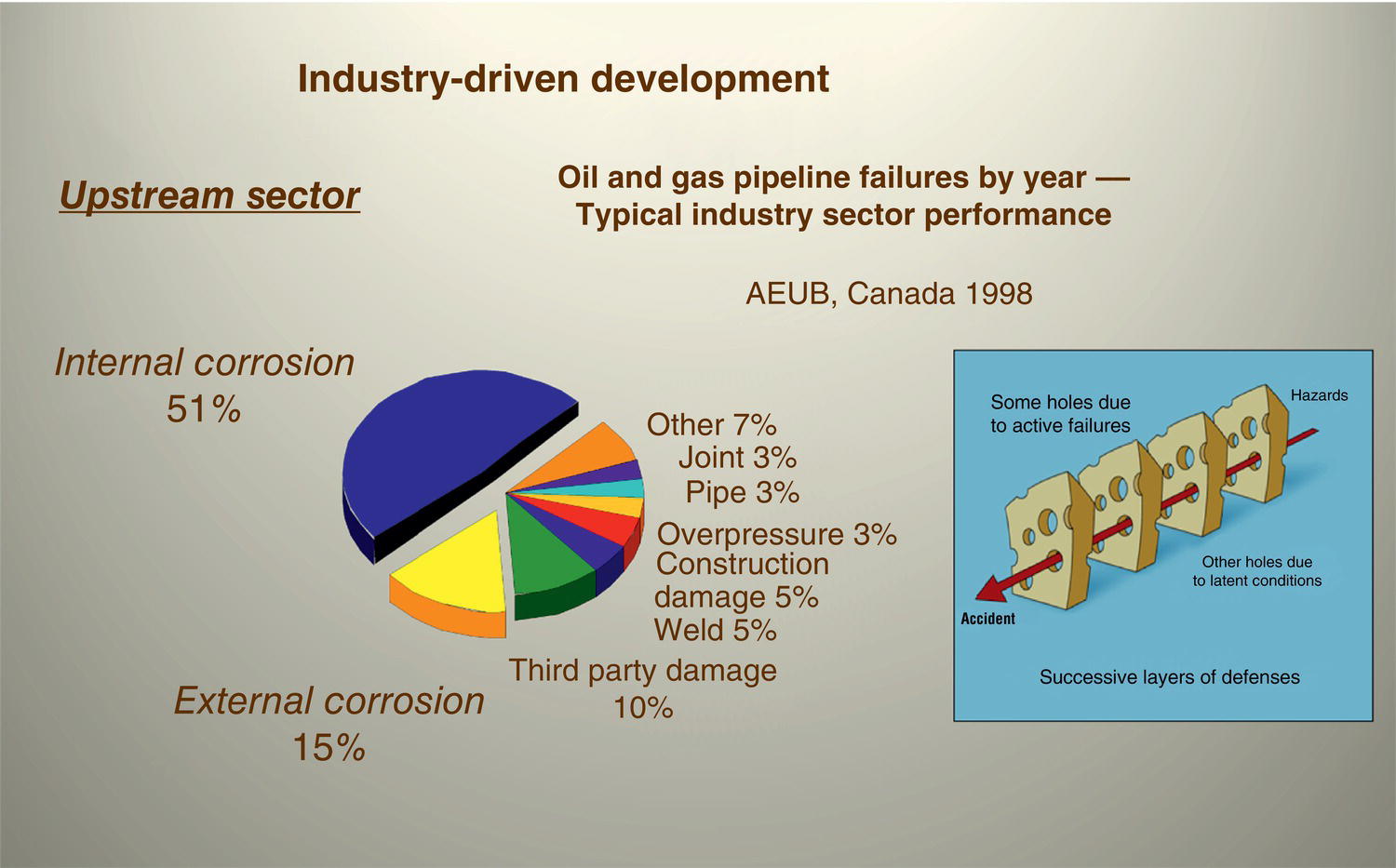
68.2 Challenges, Lessons, and Solutions
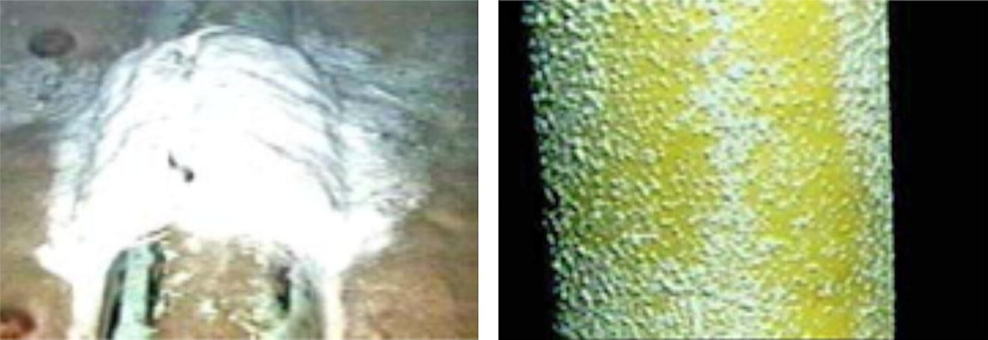
Potential mV (Ag/AgCl Ref cell)
KPI—Interpretation
Interpret Code Criteria for Carbon Steel >−800 mV: Review Evolving Industry Practices
−450 to −550
Freely corrosive
−550 to −650
Partially corrosive
−650 to −750
Inadequate/partial CP
−800 to −900
Good CP (<−820 KPI threshold for action)
−900 to −1000
Optimum KPI (should also combat MIC), including newly observed “Rusticles”
−1000 to −1100
CP ok but watch with care ~ nascent hydrogen initiation giving H2 ↑ and embrittlement (HE)
≫−1100 mV overprotection zone
Red flag (HE/coat disbondment, etc.) 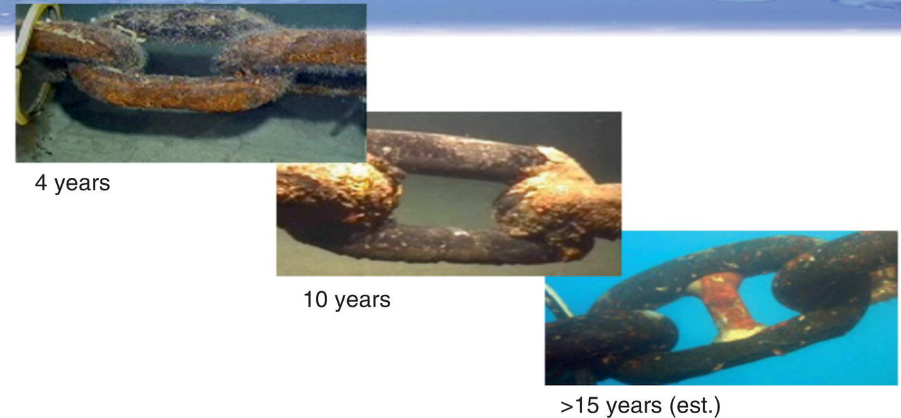
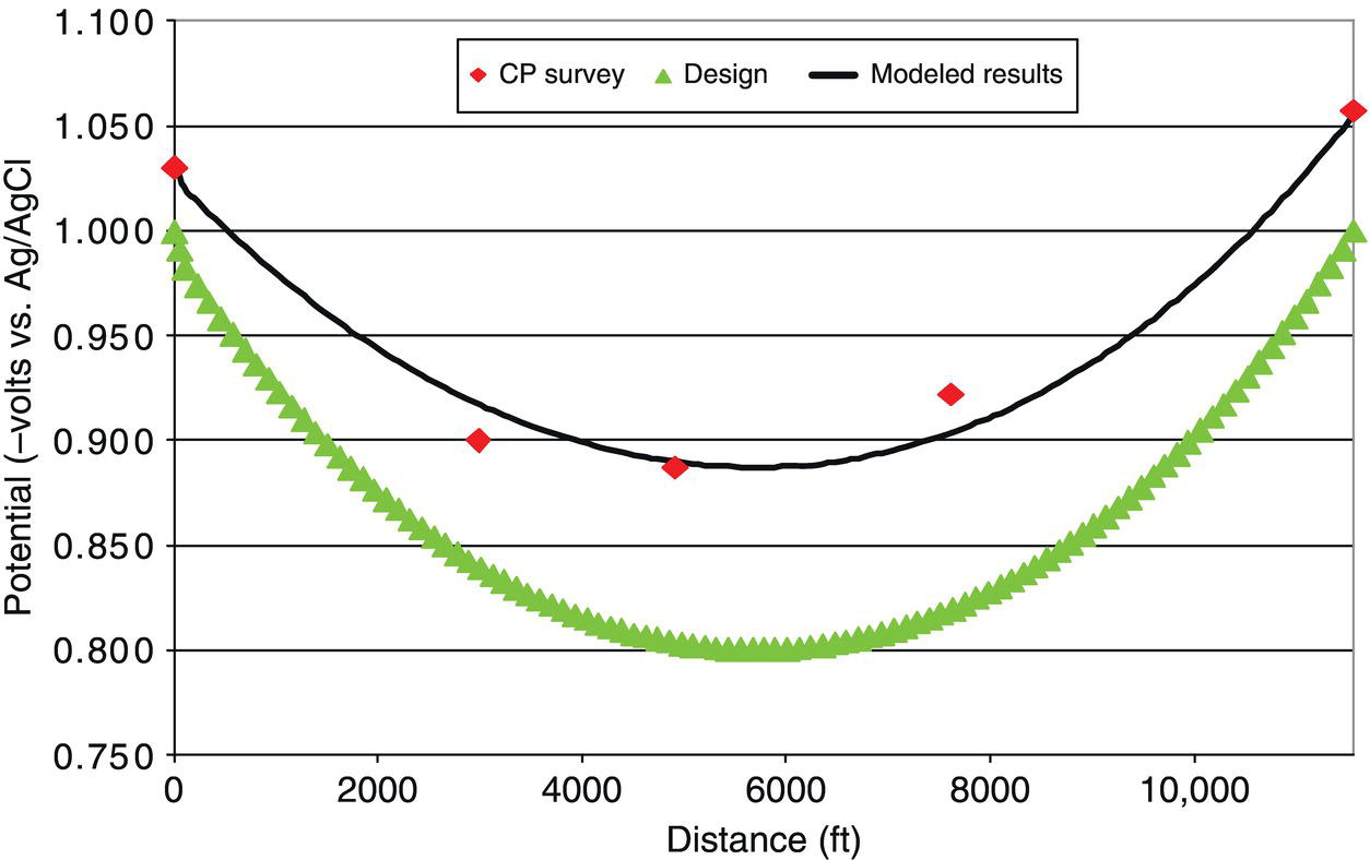
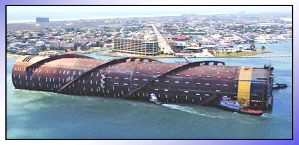
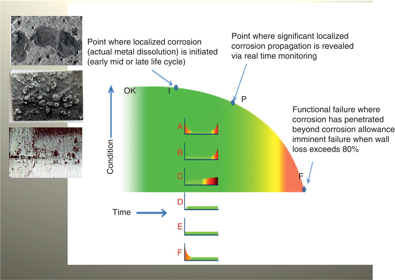
68.3 Life Cycle
68.3.1 Fitness for Corrosion Service
68.3.2 Conventional and Performance-Based Corrosion Management
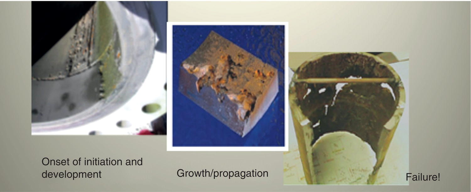
68.3.3 Corrosion Risk-Based Performance Goals
68.3.4 Inherent Safe Design (ISD) and Project Phases of a Production Development
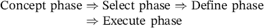
68.3.5 Link Between ISD and Corrosion Management
Localized Corrosion Stimulus
Threat Level (High/Medium/Low)
CO2
M
H2S
L (possible water injection and other life cycle changes, such as reservoir scouring, bacterial presence/dependency)
Dissolved oxygen
L
Chlorides
M
Crevice attack
L
Extent of filming/scaling/passivation breakdown
M (possible electrochemical testing akin to ASTM G01 preferably in site sampled fluids
Pitting (Mesa) attack
M
Erosion
L (potentially H)
Flow-assisted corrosion (FAC)
M
Liquid impingement
L
Corrosion fatigue
L
Stress (cold work, residual, installation, operational), including internal SCC, and so on
L
Surface roughness
L/M
MIC (planktonic/sessile)
M/H
Wettability (water/oil/condensate)
H
Pre-Corrosion (via poor preservation)
L
Physical conditions (P, T, V)
L
Flow assurance phenomenon
L
Galvanic corrosion
L
Weldment corrosion (PM, WM, HAZ)
L
TOL
L
BOL
L/M
Any other (?)
NA
Weighted Aggregate
M
68.3.6 Risk-Based Inspection and Monitoring
68.3.7 Life Extension
68.4 Case Histories
68.4.1 Fit-for-Purpose Solutions
68.4.2 Methods and Techniques of Failure Analysis
68.4.3 Failure Mechanisms and Excursions Outside the Design Envelope
General thinning (uniform corrosion)—rarely problematic—issues when localized
Pitting attack (pre-corrosiona/BOL/TOL)
Crevice corrosion (occluded cells/dead legs)a
Stress-induced corrosion (SCC, SSC, HE/HIC, SOHIC, etc.) Corrosion fatiguea
MIC/fungal corrosiona
Galvanic corrosion (mixed materials)
Filiform/under film corrosion Intergranular corrosion Fretting/galling
Corrosion under insulationa, including under deposits Weld corrosion (HAZ, PM, WM)a
Erosion/flow-induced corrosion (Cav/Imp, etc.)a
CO2/H2S localized corrosion (major threat)a
Corrosion under excursions: A more modern term CUE to reflect differing corrosion mechanisms being restricted to periodic raised or diminished dissolution under say temporary process change, transient, upset, or shutdown conditions. Often leading to increased corrosion once the steady state is restored.
Update: Under deposit corrosion (UDC) is now more conventionally applied to internal pipe. In contrast, corrosion under deposits (CUD), while equally problematic, is suggested to reflect external pipe. The differentiation is necessary to avoid confusion as both mechanisms are technically quite different.
68.4.4 Corrosion and Integrity Risk
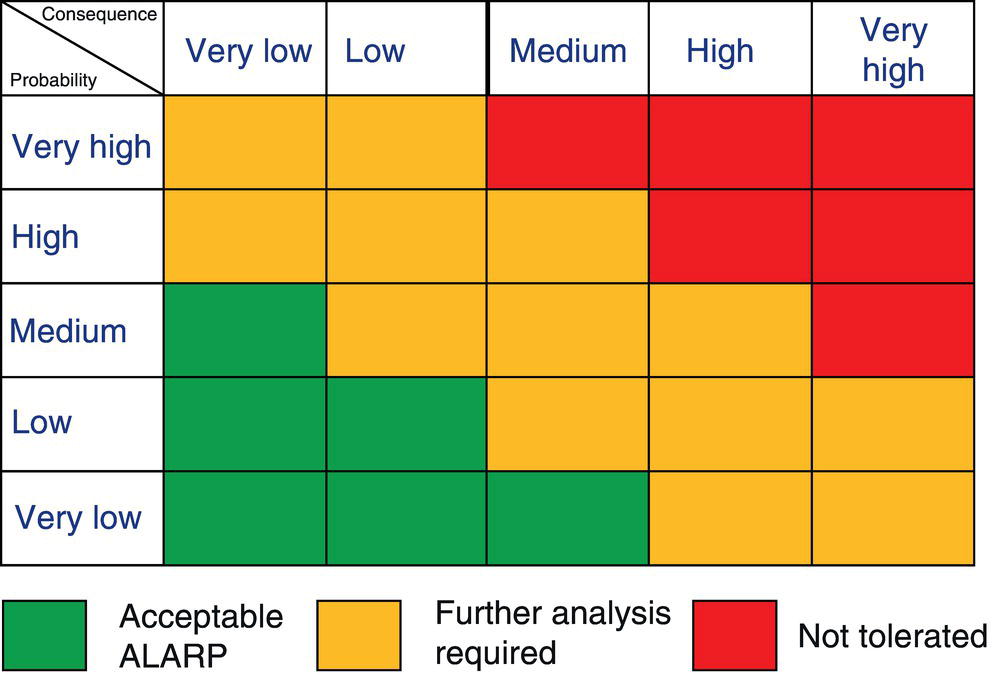
68.4.5 Corrosion Failures
68.4.6 Localized Corrosion Mechanisms in the Offshore Oil and Gas Industry
68.4.7 Pictorial Gallery of Localized Corrosion and Cracking
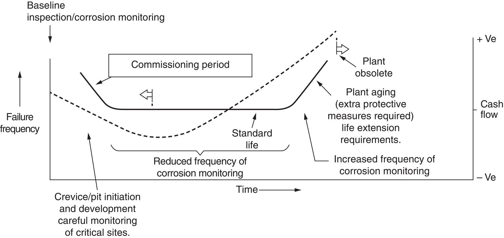
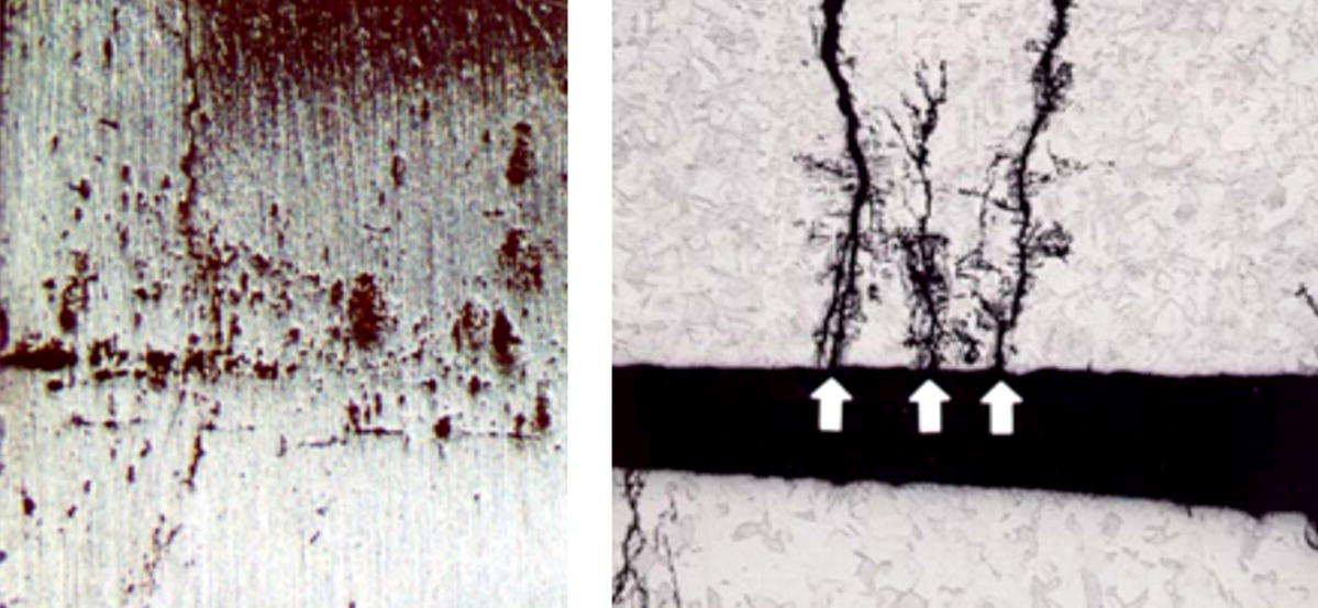
68.4.7.1 Mechanical and Environmental Cracking
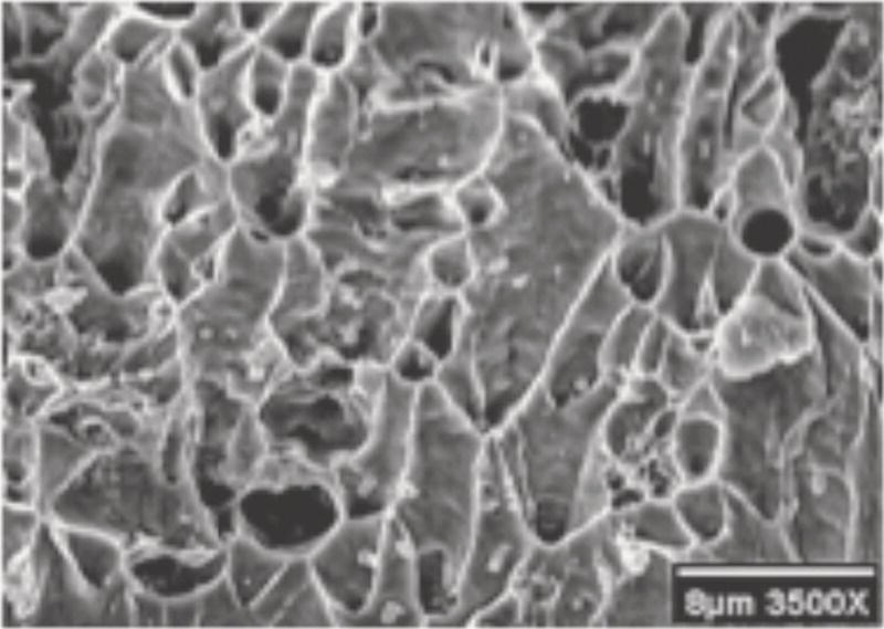
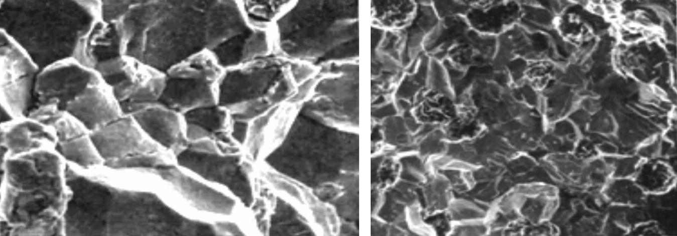
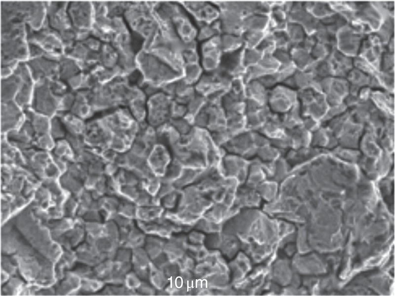
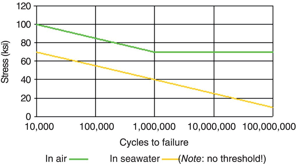
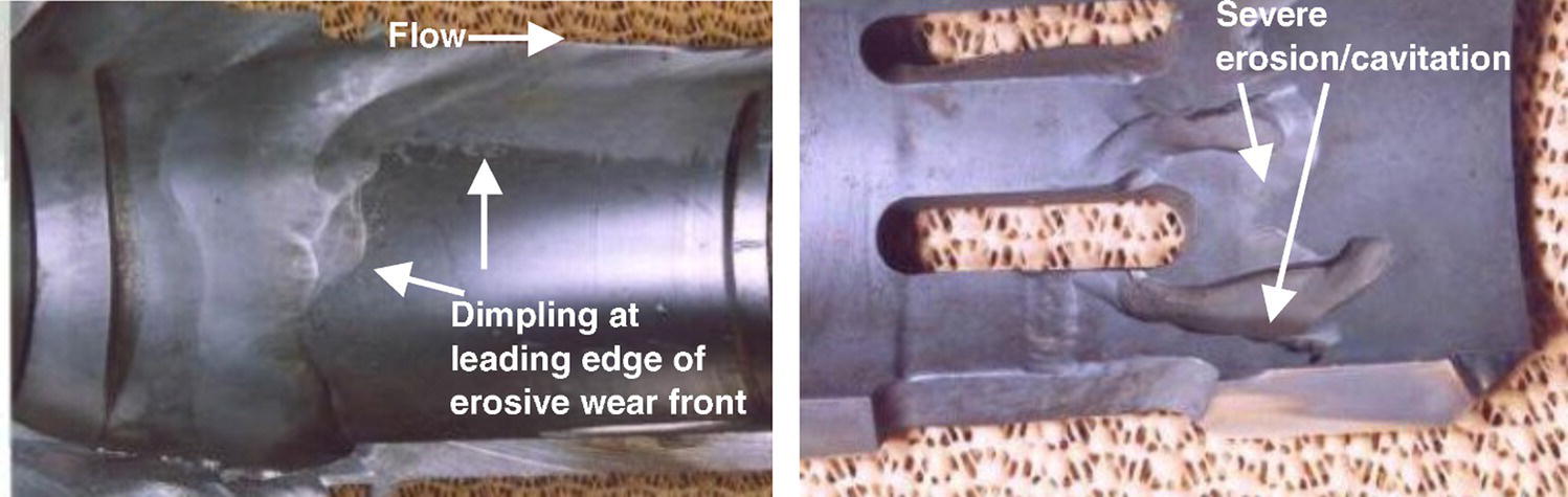
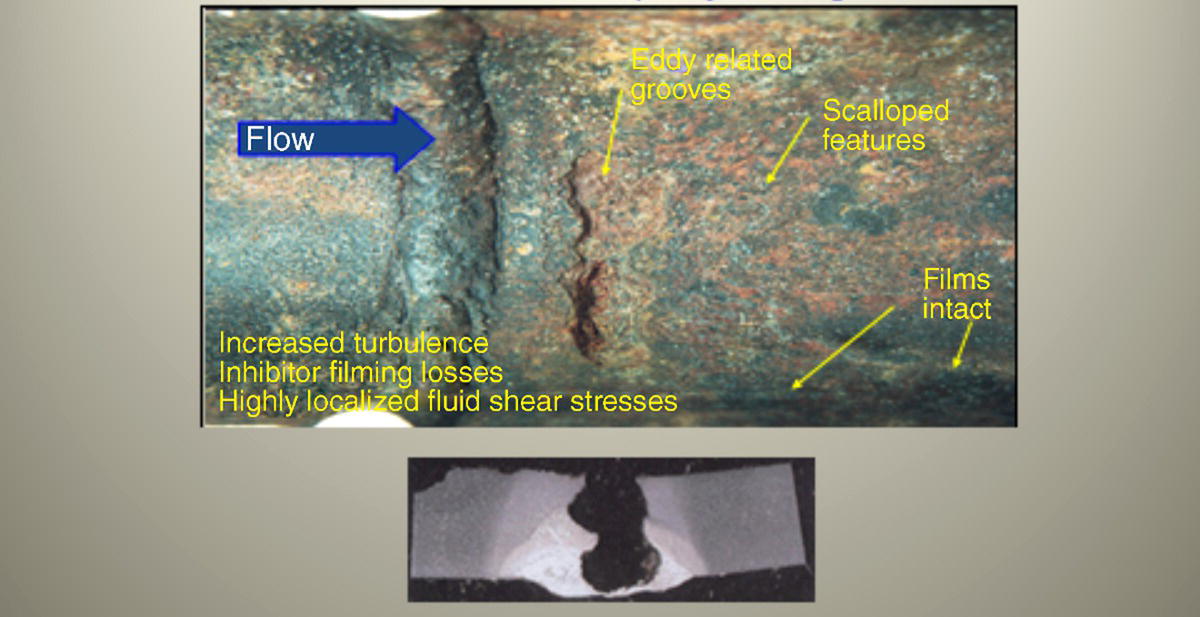
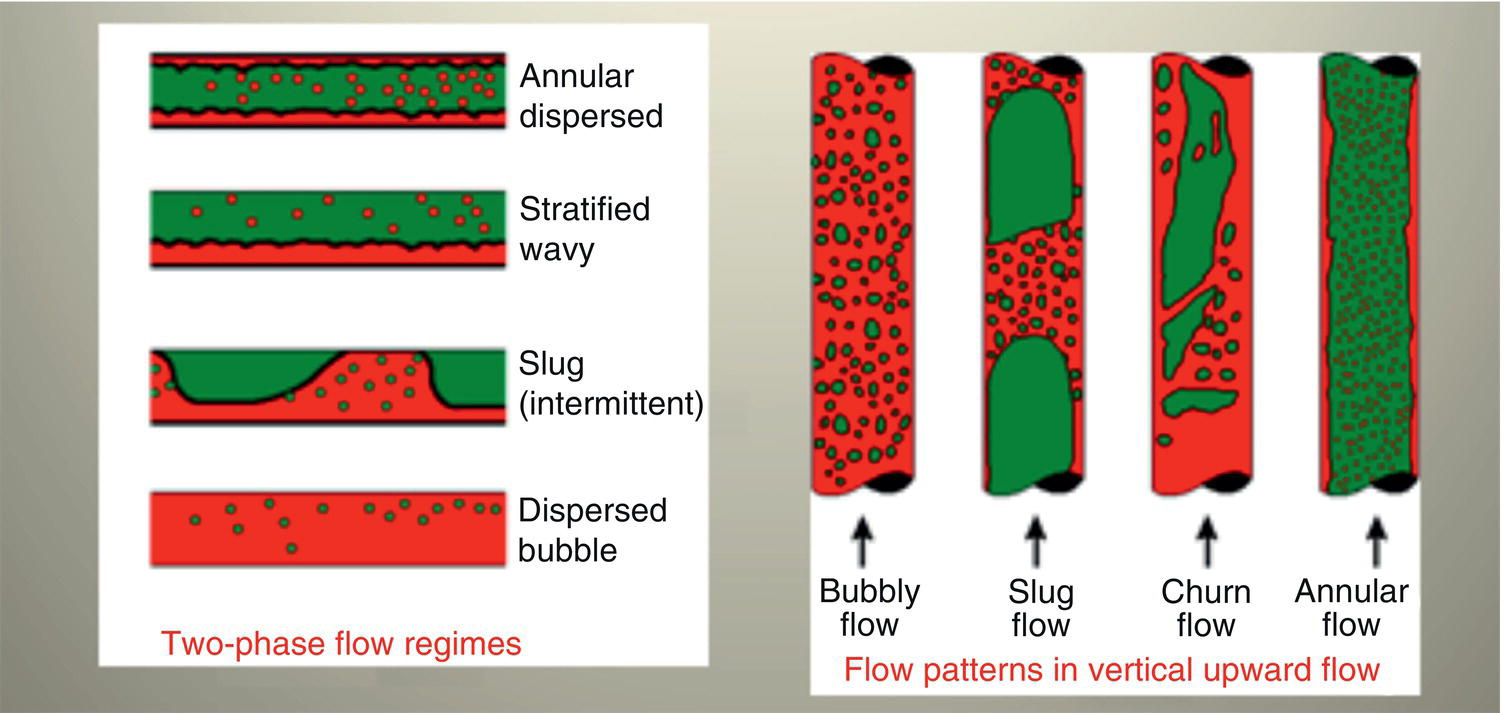
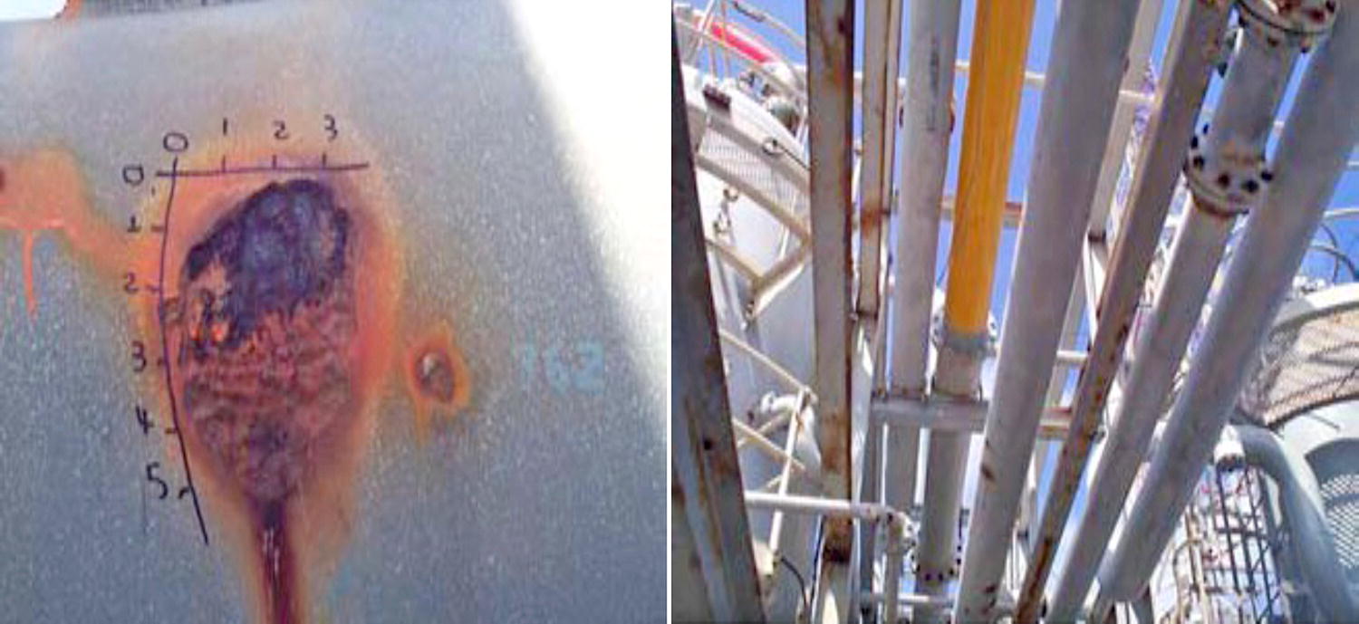
68.4.8 Failure Analysis Check Sheet Listing
68.5 Codes, Standards, Recommended Practices, and Regulations
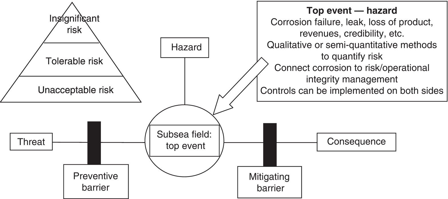
Step 1
Define scope
Step 2
Corrosion review
Step 3
Develop strategy
Step 4
Develop bowties
Step 5
Inspection
Step 6
Data management
Step 7
Reporting
Step 8
Corrosion and integrity statement (3, 6, or 12 monthly depending on risk assessment)
Step 9
Fit-for-purpose solutions
Step 10
Reappraisal or verification—feedback LL; to step 1
68.6 Corrosion Risk Analysis, Inspection, and Monitoring Methodologies
68.6.1 Risk and Reliability in the Corrosion Context
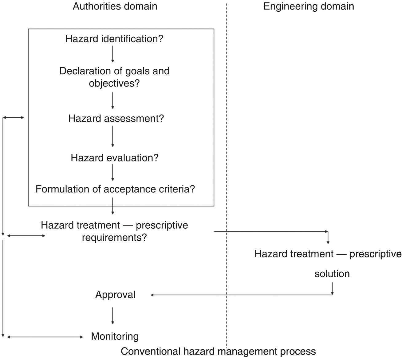
68.6.1.1 Focal Point 1: Production Availability

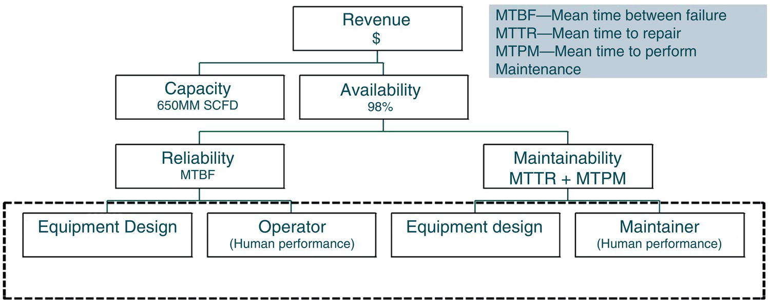
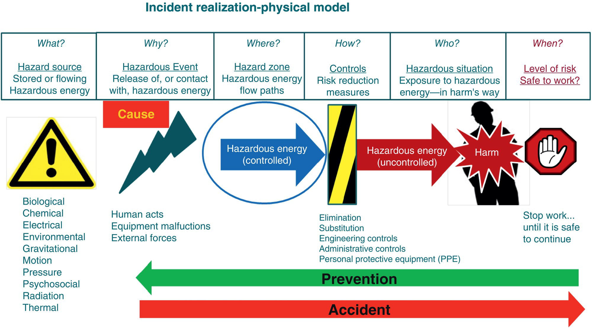
68.6.1.2 Focal Point 2: Incident Realization
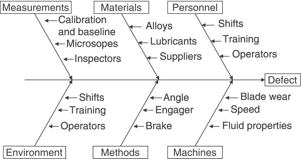
68.6.1.3 Focal Point 3: Life-cycle Perspective
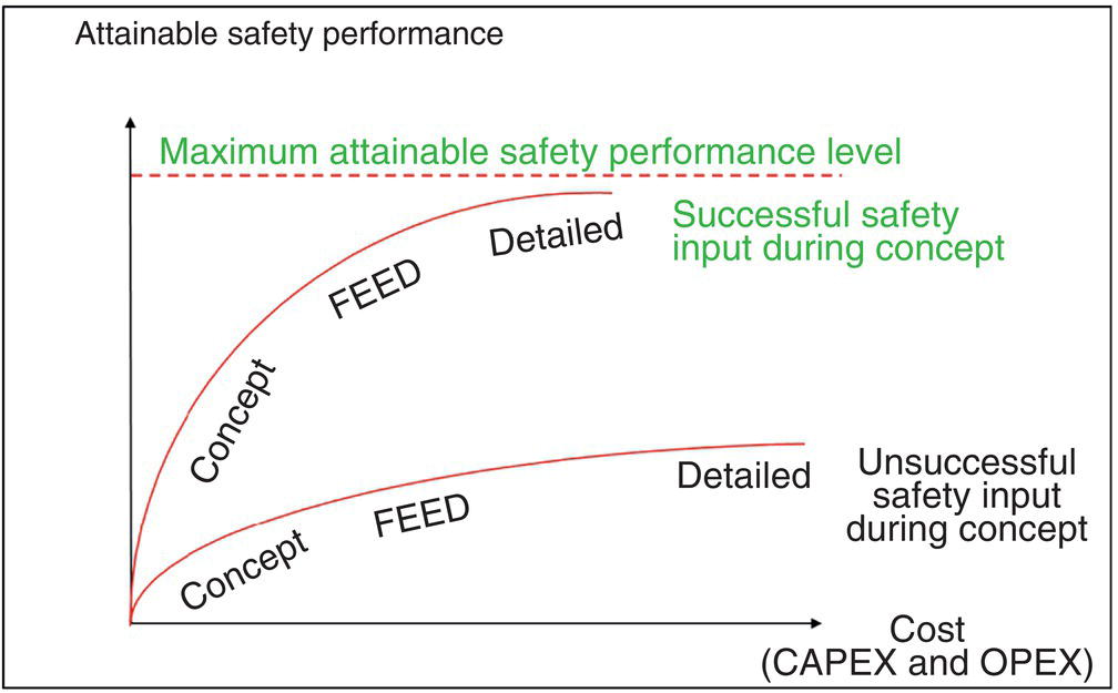
68.6.2 Safety Management Systems and Corrosion Risk
68.6.3 Formal or Structured Hazard or Risk Assessment
68.6.3.1 Step 1: Hazard Identification
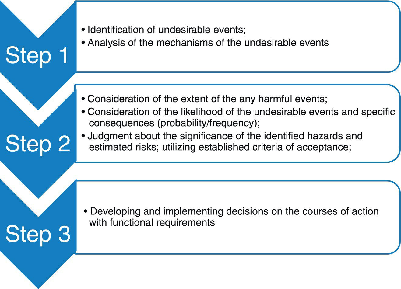
68.6.3.2 Step 2: Hazard Analysis/Assessment
68.6.3.3 Step 3: Hazard/Risk Management
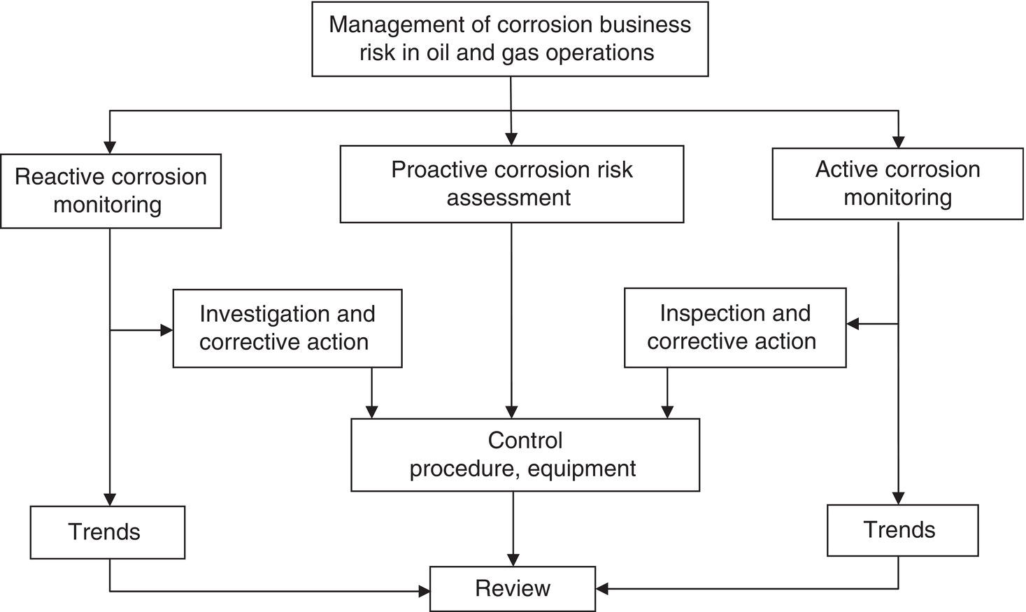
68.7 Lessons Learned, Recommendations, and Future Strategies
68.7.1 Lessons Learned—Update and Discussion
68.7.2 Recommendations and Future Strategies
Caveat and Acknowledgments
References
Bibliography
Notes