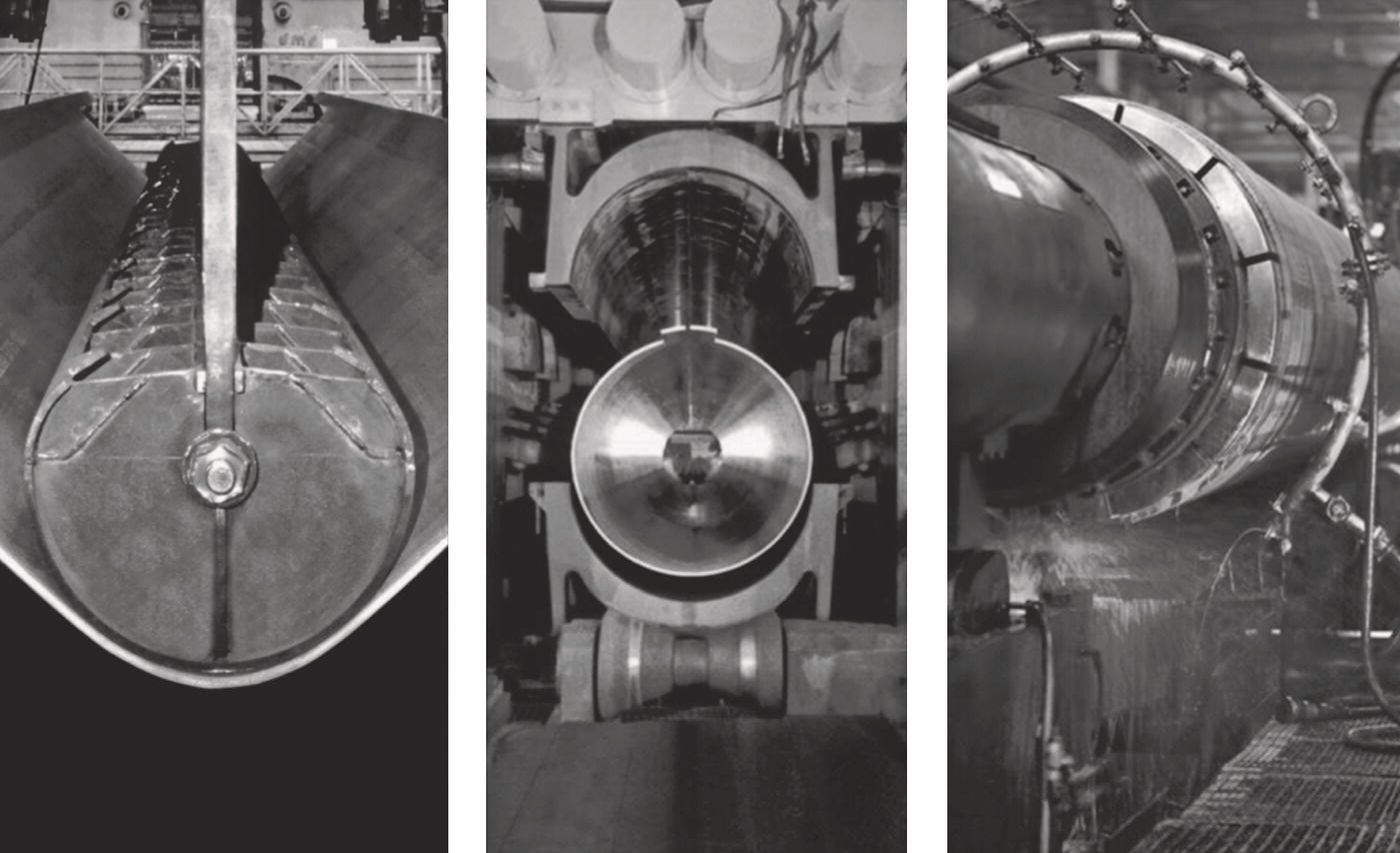
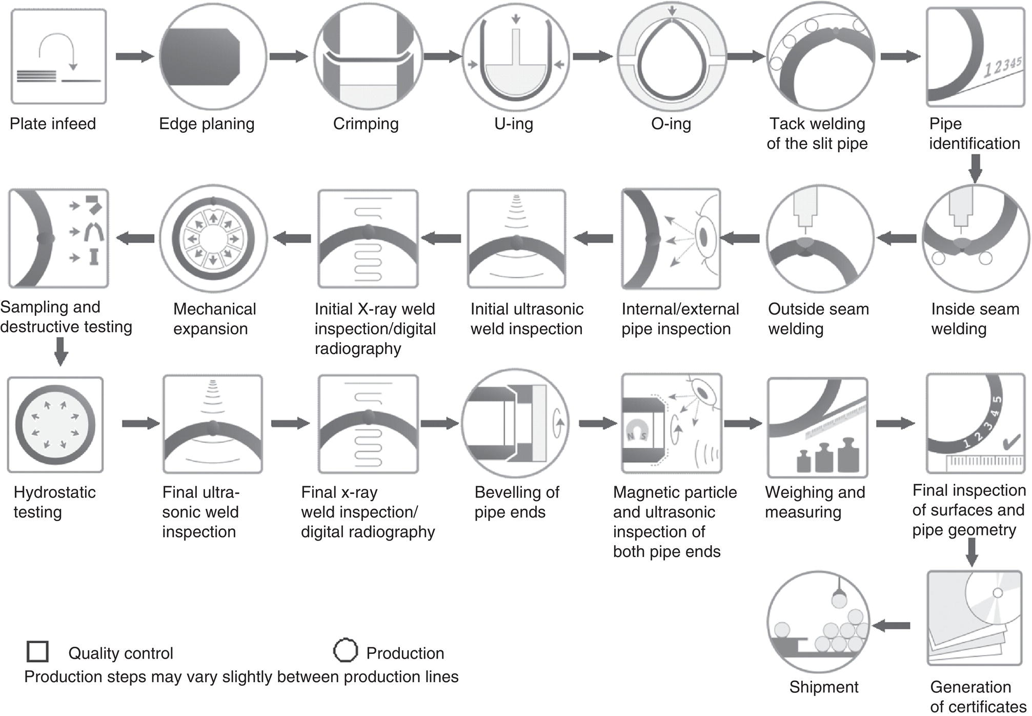
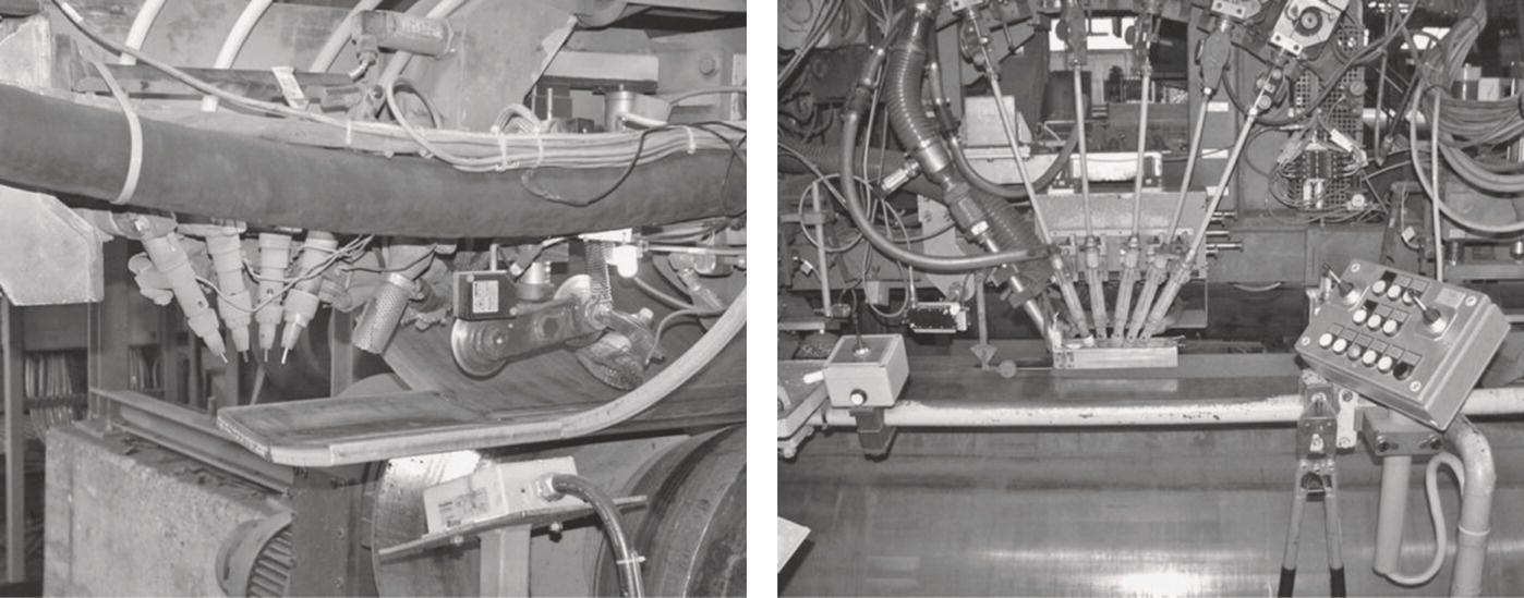
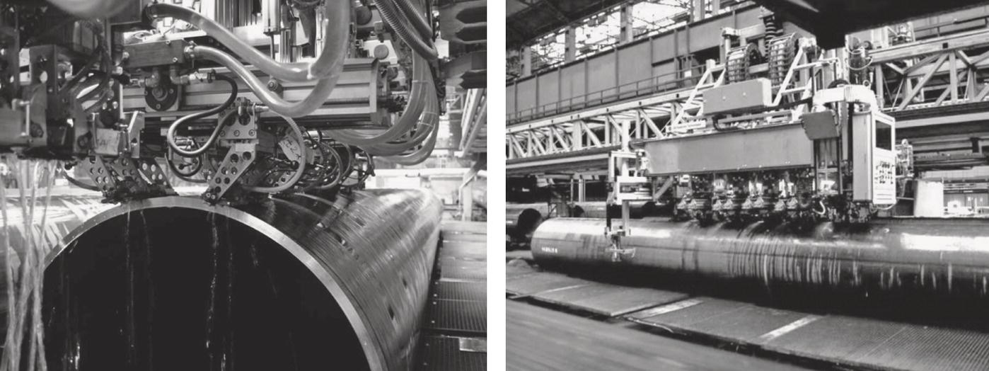
Christoph Kalwa EUROPIPE GmbH, Mülheim an der Ruhr, Germany For transporting large quantities of hydrocarbons over long distances, longitudinal submerged arc welded (LSAW) pipes have been used for decades. When operational conditions require high wall thickness due to high internal or external pressures, LSAW pipes are commonly the most economical solution. The experience gained over many years of production and operation of this type of pipe has resulted in a thorough understanding of the pipe material with detailed knowledge so that the material can be modified to meet specific and demanding requirements. This is appreciated very much in the pipeline industry, especially when harsh conditions with respect to corrosion, deformation capability, or low-temperature toughness are involved. In LSAW pipe mills, processes form heavy carbon steel plates to a pipe shape in cold condition. The heavy plate is the pipe’s prematerial, on which many of the pipe properties depend. The state-of-the-art technique is to roll slabs by thermomechanical-controlled processing, where each rolling pass is defined in a narrow temperature range and of deformation rate. Subsequent accelerated cooling generate the final plate properties, enhancing the strength of the plate. Good weldability can be achieved through the use of a lean chemistry. The pipe manufacturing designation describes the main forming process as U-forming–O-forming expansion (UOE), as shown in Figure 17.1. Alternatively, processes like three roll bending (3RB) and J-forming–C-forming–O-forming (JCO) with a forming press are in use. The processes that are installed in the pipe mill have a strong influence on dimensional limitations of the pipe and the productivity of the mill. The UOE process provides very good productivities, up to 360 m/h, but is limited, by the available press forces, to about 50 mm pipe wall thickness. Depending on the equipment, up to 18 m long pipe can be manufactured. The 3RB process is usually limited to 25 mm wall thickness and 12 m pipe length. The JCO process opens the wall thickness ranging above 50 mm, but the productivity stays below 100 m/h. Some mills with the JCO process provide pipes with length up to 18 m. In all cases, the pipe diameter is limited by the forming tools and, more importantly, by the available plate width. Figure 17.2 shows an example of the production scheme of UOE pipes. It is evident in the scheme that besides all production steps many quality control steps are in place to assure the desired properties and a proper documentation of the pipes. After assembling run-on-run-off tabs and forming, the plate edges are joint by a continuous tack weld, which also serves as backing for the subsequent seam welding. This is conducted by submerged arc welding and dissolves the initial tack weld (Figure 17.3). In most cases, a two-layer technique is used with one layer welded from the inside followed by a second layer from the outside. For high productivity, a sufficient deposition rate is mandatory, which is provided by multiwire technique with up to five wires. Especially for high wall thicknesses the heat input is high and affects the zone around the weld significantly, which may result in low toughness in localized areas. After the submerged arc welding, the tabs can be cut and scrapped. In many cases, a subsequent mechanical expansion completes the forming process. The main purpose for expansion is to shape the pipe perfectly round for a better girth welding performance. Besides this issue, there are beneficial influences with respect to homogenization and decrease of residual stresses. Because the mechanical expansion stresses the pipes above yield strength, the pipe is stressed more than that in the hydrostatic test, giving an additional safety for pipe integrity. Figure 17.1 Forming stages of UOE process. (With permission of EUROPIPE GmbH.) Figure 17.2 Production scheme for UOE pipes. (With permission of EUROPIPE GmbH.) Figure 17.3 Inside and outside welding process. (With permission of EUROPIPE GmbH.) In the final pipe production steps, the inside and outside weld reinforcements are removed for a proper preparation for coating and field welding equipment. Weld bevels or square cut ends are machined for later field welding. Various quality assurance and quality control steps accompany the entire process. Permanent recording of the process parameters, the evaluation of all data, and a deep understanding of the interaction between all the processes are essential to ensure product quality [1]. A full traceability from the steel mill’s slab to the coated pipe is mandatory. Modern pipe mills use electronic data processing for recording time and parameters of each working step. The same is required for the prematerial deliveries back to the steel mill. For a reliable seam weld, a clean weld grove and a homogeneous tack weld serve as good preconditions. These result in stable welding processes with stable welding parameters. Nondestructive testing (NDT) methods, that is, visual inspection, ultrasonic testing, and radiography, prove the soundness of the longitudinal weld. As technical rules require no weld repairs after expansion, the production flow should consider measures to identify any indication as early as possible before mechanical expansion. The NDT methods should align with potential threats of the high-heat-input welding process, which are pores, slags, undercuts, and lack of penetration. The mechanical expansion finalizes the main production steps and no further step affects mechanical and dimensional properties. Samples are cut for mechanical testing, representing a certain lot of similar pipes. A hydrostatic test stresses the pipe at a higher level than any operational pressure might apply. Most specifications define a stress at 90% of the specified minimum yield strength some other specify higher values. With respect to integrity, mechanically expanded pipes are stressed at a higher level during the expansion process, because the desired plastic deformation ranges in stress regions above the actual yield strength. The entire weld is examined with an automatic ultrasonic system (Figure 17.4) with probes assembled in such a way that they indicate longitudinal and transverse flaws in the pipe volume and the fusion line. In most cases, an NDT reference pipe with artificial defects, bore holes, and notches, has to be fed in to the ultrasound equipment frequently to prove the sensitivity of the system. Indications should be marked explicitly with paint or stored by electronic measures and examined with radiography and manual ultrasonic testing to exclude false echoes or acceptable indications. Figure 17.4 Automatic ultrasonic testing equipment. (With permission of EUROPIPE GmbH.) Figure 17.5 Digital radiography. (With permission of EUROPIPE GmbH.) A special focus is put on the pipe ends with respect to good preconditions for girth welding and NDT on site. Radiography assures the soundness of the seam weld’s extreme 200 mm at both pipe ends with respect to volumetric indications. For repeatable results and good performance, digital radiography is an up-to-date technology (Figure 17.5). Ultrasonic testing on laminations of the extreme 50 mm as well as surface testing of the welding phase by magnetic particle inspection or eddy current testing adds benefit to ensuring pipe end’s soundness. Besides NDT of the weld, geometry defines the pipe quality. Low tolerances to the perfect round shape at the pipe ends are beneficial for the performance of the pipe laying process. This issue becomes more important when operational reasons, such as high strain conditions in the longitudinal direction caused by ground movement, require low offset for the girth welds. For deep-sea applications, ovality of the entire pipe is an issue for promoting buckling under high external pressures. Modern pipe mills are using automatic laser-based measuring systems, which allow accurate, personnel-independent evaluation of geometric properties. Nevertheless, manual measuring methods are in place, which give less accurate results. LSAW pipes are used in sizes from 16 in. (406 mm) to 60 in. (1520 mm) with wall thicknesses from 7 to 60 mm. Pipe size and wall thickness depend mainly on the available plates, but also forces of the pipe forming process limit the pipe size and wall thickness. A very thick pipe wall above 40 mm requires an extremely high heat input, which might result in selecting a multilayer technique for welding to cope with weakening and loss of toughness of the seam weld’s heat affected zone. Also in terms of grades, the prematerial limits the supplies. In many cases, pipeline design uses grades with strength classes up to L 485 (X70), but also grade L 555 (X80) is frequently in use. Even higher grades like L 690 (X100) and L 830 (X120) have been developed, but the pipeline market is reluctant to use such very-high-strength pipe grades. Higher grades allow reduction of the pipe weight with smaller wall thickness at the same diameter and operational pressure, which is beneficial for pipe transport and laying activities, but they might cause further challenges in pipeline design, pipe fittings, and girth welding. Pipelines are the arteries of industrial development. The areas where the gas and oil are explored rely on safe operation of the pipeline grid to secure continuous prosperity from sales of gas and oil. The areas where the gas users are located depend on a safe supply for the continuous operation of their industry. Environmental and population safety aspects trigger high quality requirements and appeal to the responsibility of all involved bodies to put all efforts into safe pipeline operation. In many cases, pipelines are running onshore with no special requirements. For this use, international standards from API or ISO describe the required properties of the pipes. The different areas where the resources are explored, the different composition of media to be transported, and the different areas pipelines are running through, all demand different approaches in pipeline design and linked to this require specific pipe material [2–4]. Offshore pipelines link platforms at subsea wells with the processing devices onshore. Offshore pipelines may link the national pipeline grid of supply countries with the grid of user countries, crossing in some cases deep-sea areas. The high pressure requires heavy walls for the pipes, which can be reduced with decreasing pressure along the pipeline. The pipe laying process also controls the requirements of the pipes. For an efficient pipe laying process with respect to welding, a close to perfect round shape of the pipe ends is beneficial. As longitudinal stresses from bending and weight occur during the pipe laying, longitudinal strength requirements play an important role. High external pressures in deep-sea regions bear the risk of pipe collapse during laying. Avoiding this requires low ovality of the entire pipe length and controlled compression pipe properties. An increasing number of pipelines are being installed in polar environments in Canada, Russia, and Norway, where they are exposed to very low temperatures. Carbon steels have a temperature-dependent transition from high to low toughness. For arctic use, pipe material has been developed with the transition temperature below −50 °C. If the medium contains considerable amounts of hydrogen sulfide, the pipeline operator has to consider corrosion with respect to sulfide stress cracking (SSC) and hydrogen-induced cracking (HIC). These subjects are discussed in more detail in Chapters 58 and 20, respectively. Both phenomena are based on the carbon steel structure being affected by hydrogen. Embrittlement of the material causes SSC, and HIC damages the steel’s microstructure. To avoid such phenomena, the material must exhibit a high steel purity with well-controlled segregation and precipitates. Segregating elements that enhance the strength of the steel, such as carbon, manganese, niobium, etc. must be limited. In many cases, users require sour grades up to the strength level of X65. Recent developments have shown that X 70 and even X 80 can be produced as sour resistant grades. Also, pressurized hydrogen might affect the toughness properties of pipe material. Depending on hydrogen partial pressure and gas composition, the effect on material might vary. The way, how to qualify pipe material for hydrogen use is under investigation. When pipelines cross through areas with ground movement by frost heave and thaw settlement or landslides or earthquake, the pipe must be deformable to the extent required by the ground movement, to ensure safe pipeline operation. In that case, strain-based design criteria are used that require adequate deformation properties for longitudinal straining. Strain-based design is discussed in Chapter 9. Close cooperation between those responsible for pipeline design and for pipe manufacturing is necessary to ensure that the design reflects feasibility of the material. Finally, a pipe manufacturer has to cope with the requirements from local project conditions in tailoring the entire set of properties. In some cases, measures for fulfilling one set of requirements might contradict measures for other sets. In such cases, close cooperation between pipeline designers and pipe manufacturers is necessary to agree on compromises.
17
Pipe Manufacture—Longitudinal Submerged Arc Welded Large Diameter Pipe
17.1 Introduction
17.2 Manufacturing Process
17.3 Quality Control Procedures

17.4 Range of Grades and Dimensions
17.5 Typical Fields of Application
References