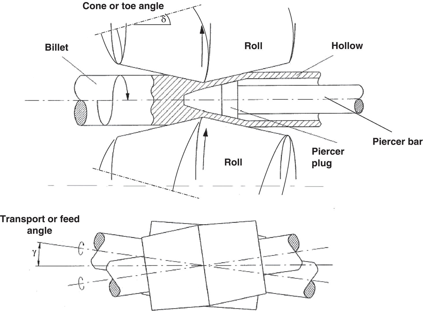
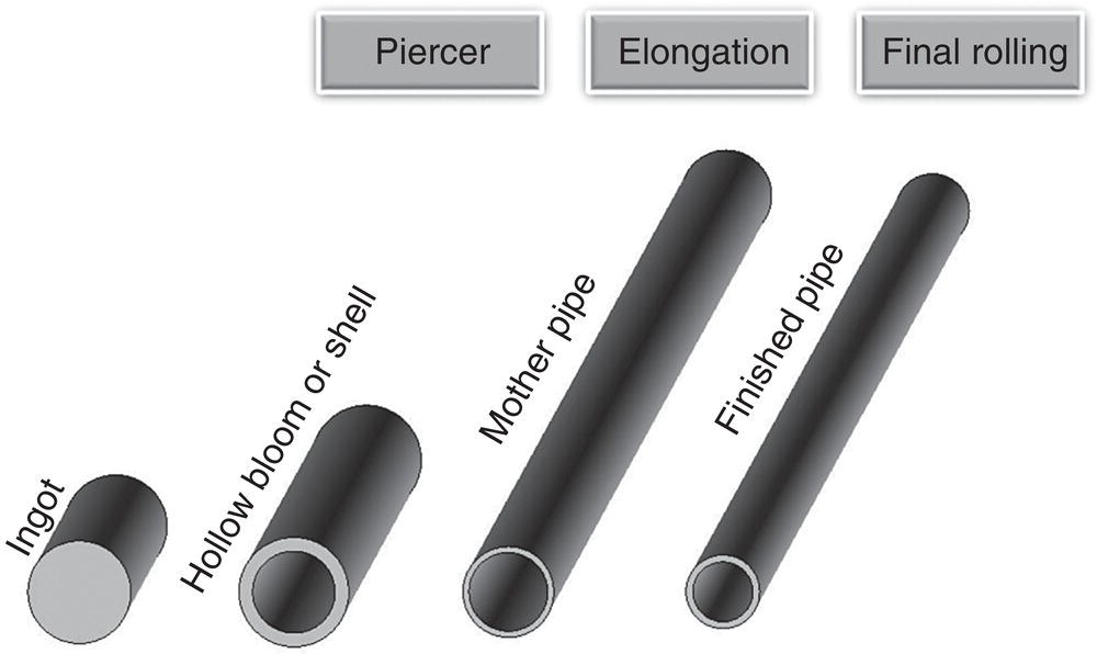
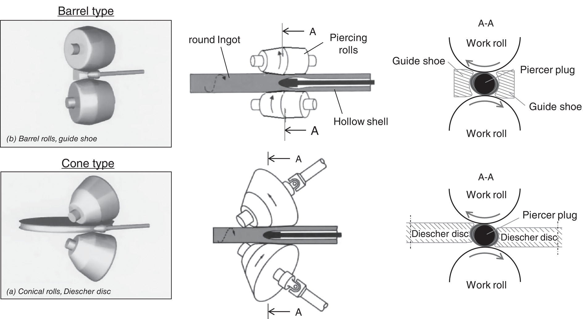
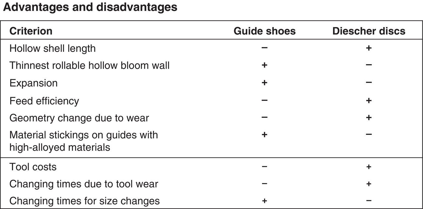
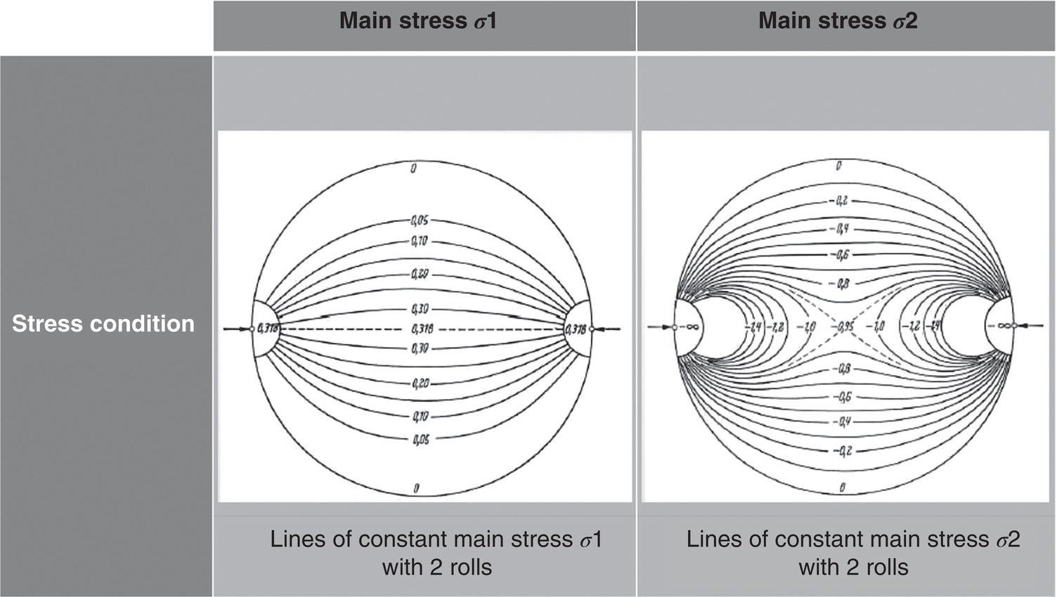
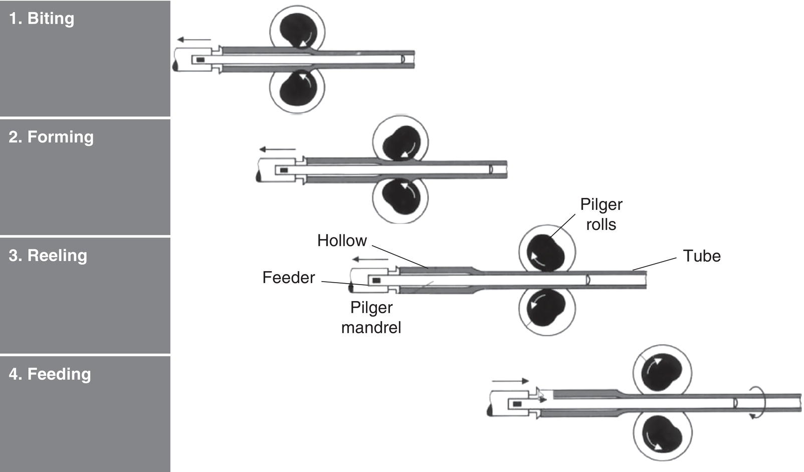
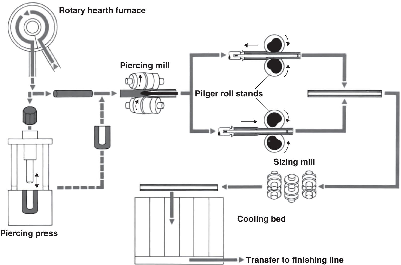
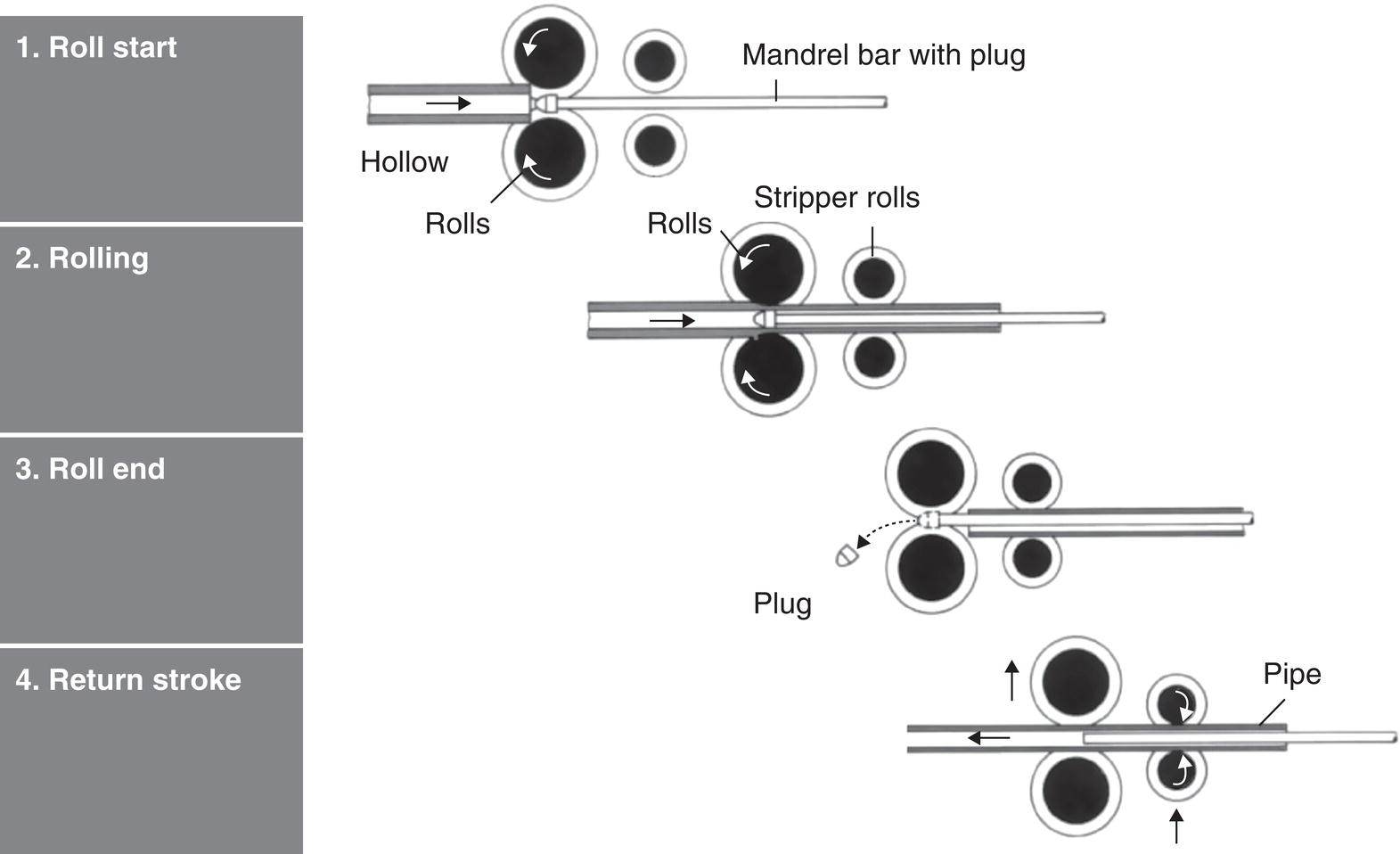
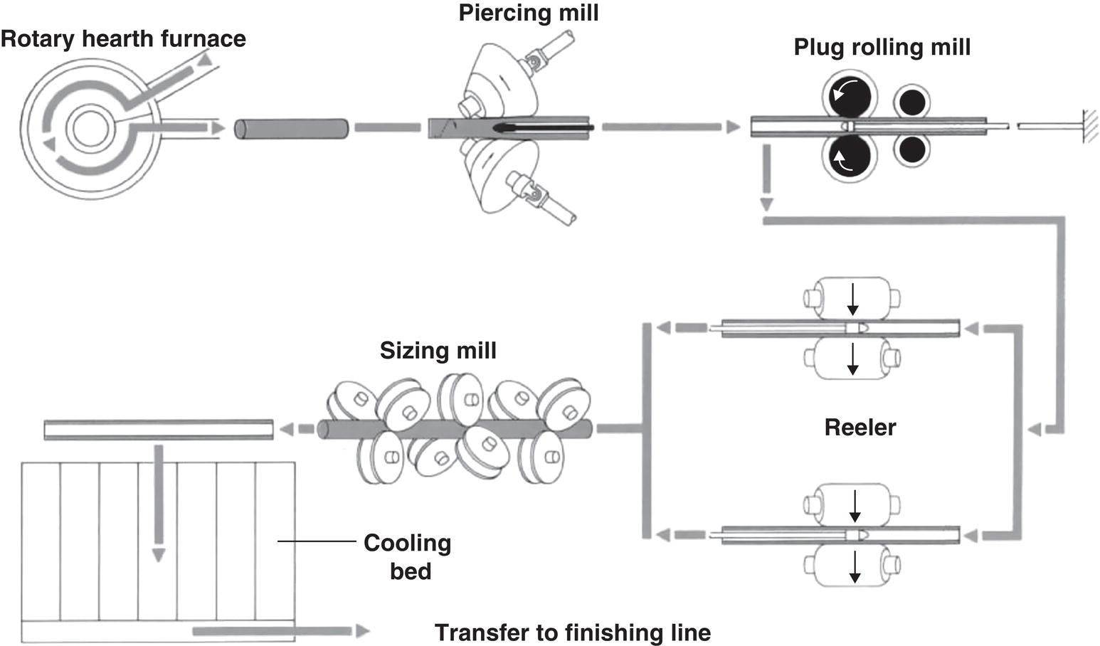
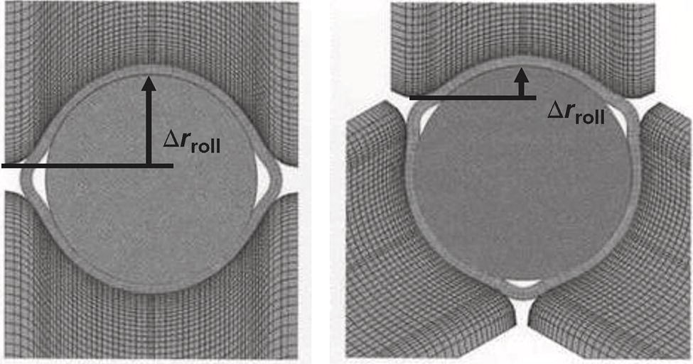
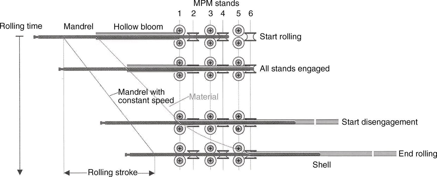
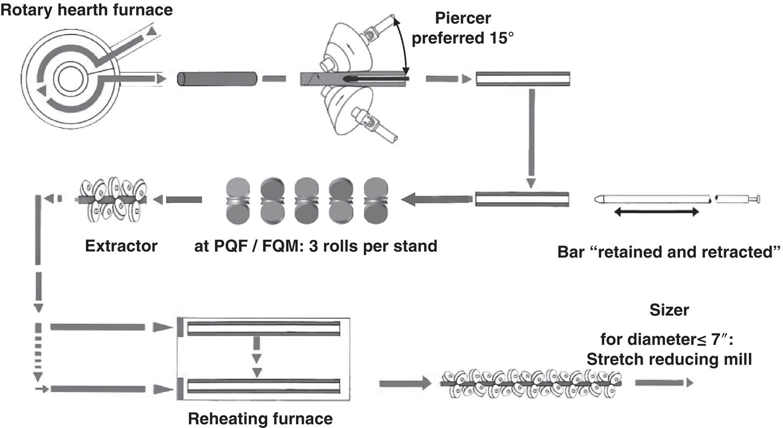
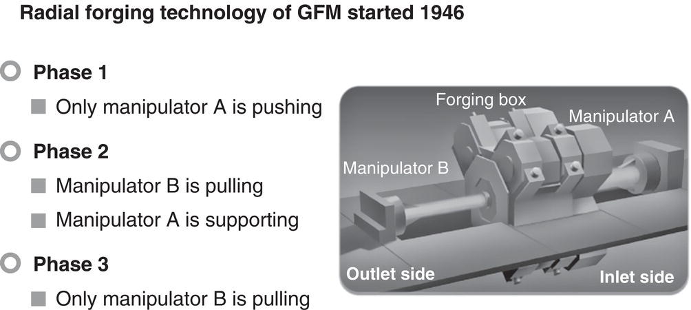
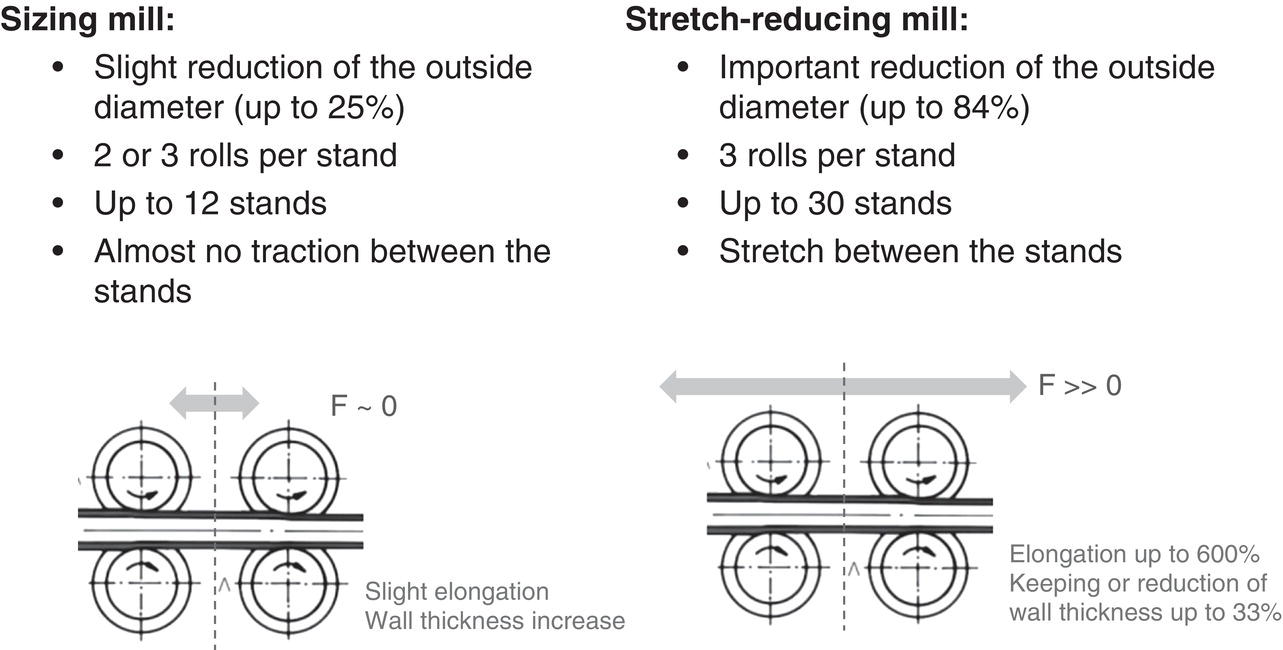
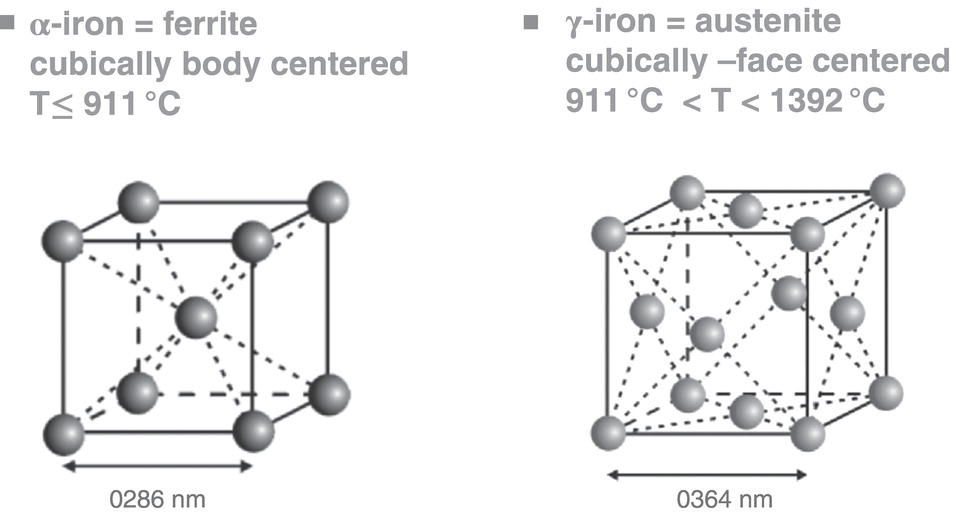
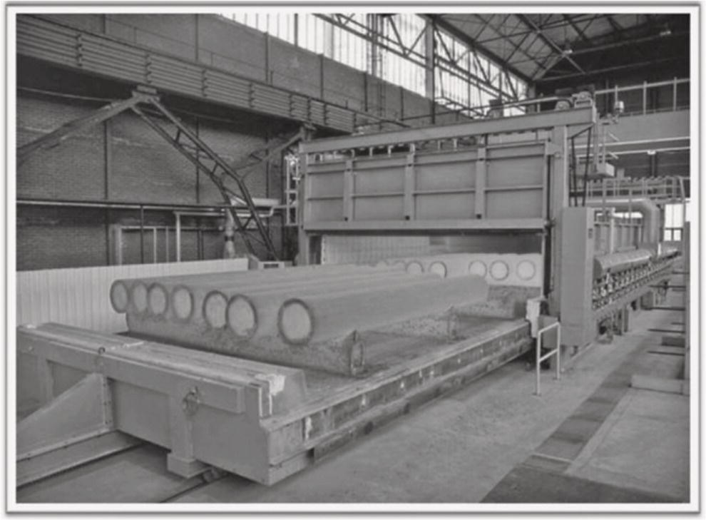
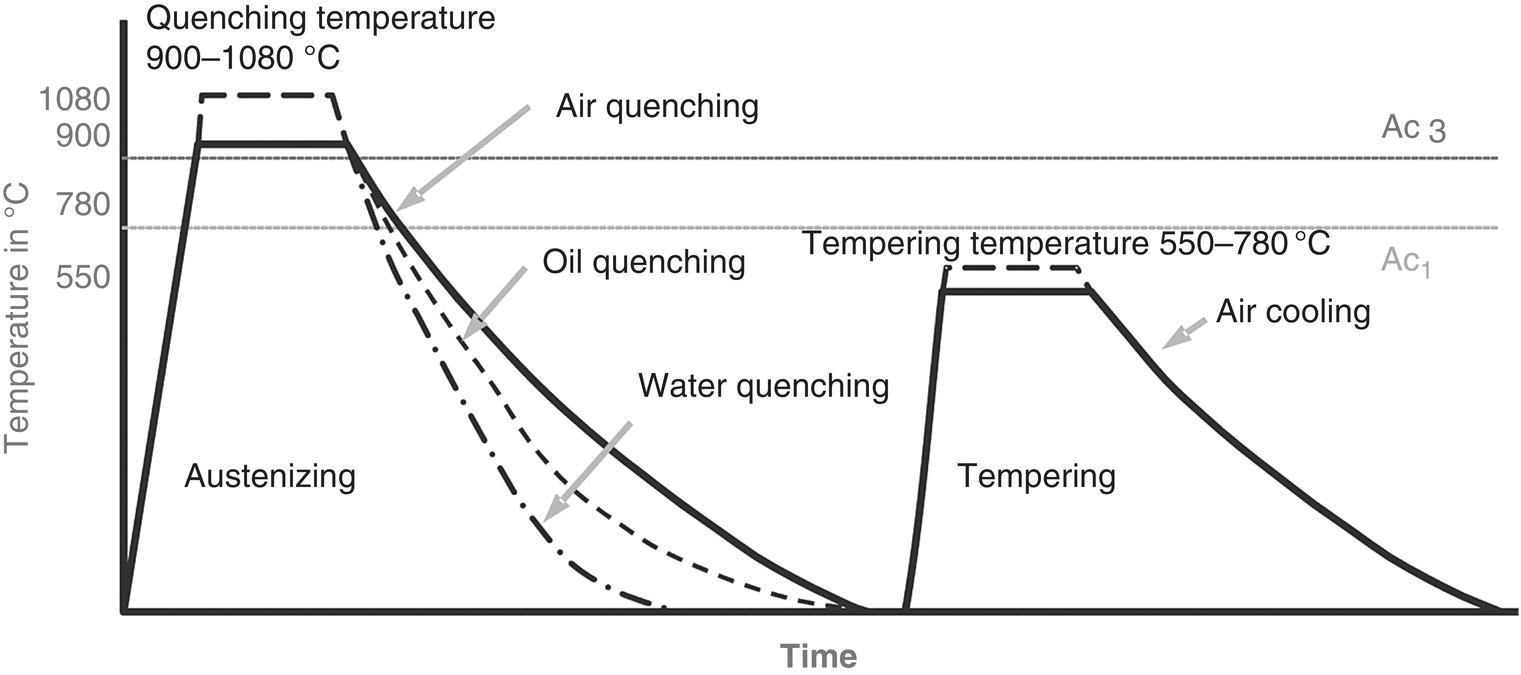
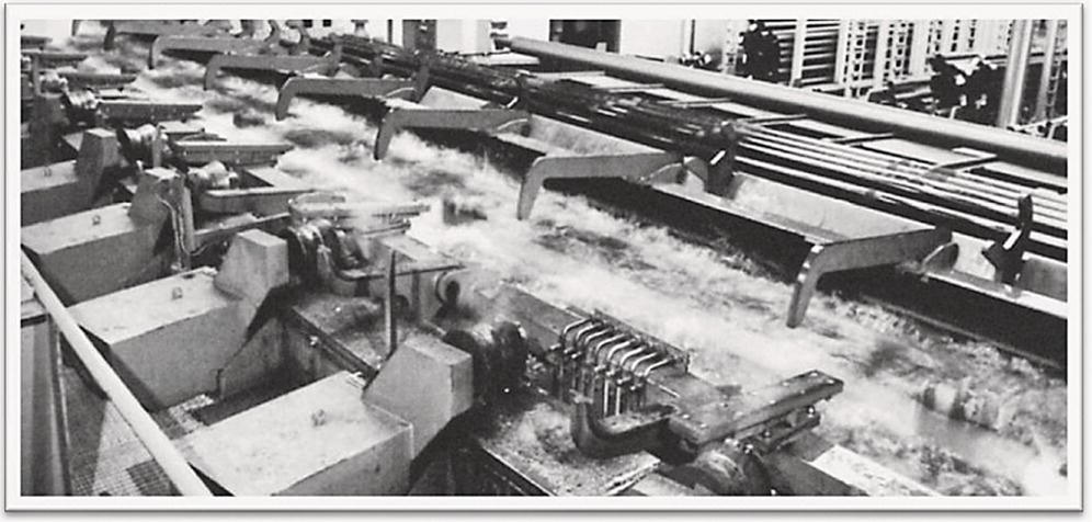
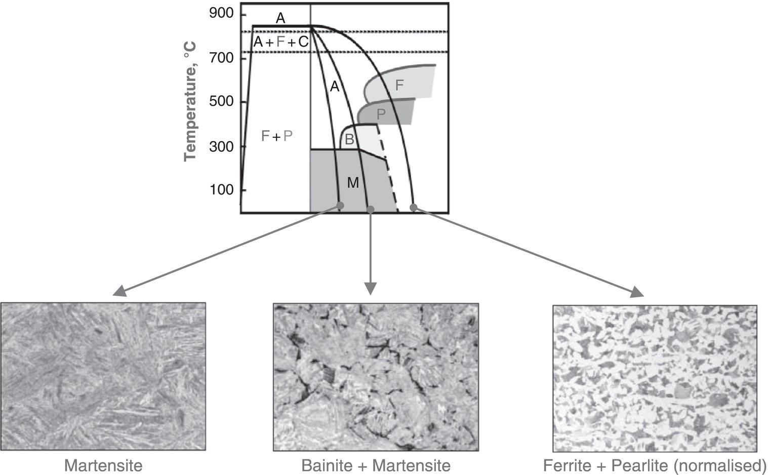
Rolf Kümmerling and Klaus Kraemer Vallourec & Mannesmann Deutschland GmbH, Düsseldorf, Germany The history of seamless steel tube starts with the Mannesmann brothers’ invention of a process for piercing solid ingots by cross rolling, see Section 19.1.2. The invention was patented in 1882. The basic principle of cross-roll piercing and the most important components are shown in Figure 19.1. The rolls arranged at an angle to each other and turning in the same direction force the billet between them into a helical motion. As it passes through the mill, it is pierced by a plug fixed to a freely rotating bar which is supported by a thrust block at the run-out end of the mill. As opposed to rolling with flat or grooved rolls, in pierce rolling the contact surfaces between the billet and the rolls are small in relation to the total billet surface being worked. In addition, the forming operation mainly takes place circumferentially, while the material is actually intended to yield axially. Consequently, the hollows produced by pierce rolling, followed by size rolling to the finished diameter without an internal tool, were not marketable as tubes. Cross-roll piercing merely allowed the production of relatively thick-walled hollows called blooms. This meant that the Mannesmann brothers had to develop an additional elongation process, which led to three rolling stages in seamless tube production that are still standard practice today, namely, piercing, elongation, and final rolling (Figure 19.2). The first production stage for nearly 90% of all seamless tubes is pierce rolling, and the final stage is size rolling or stretch reducing, see Section 19.1.7. A large number of different longitudinal and cross rolling processes have become established for the elongation stage. Therefore, the type of elongation process is used to designate the entire production chain. The first process to be employed for elongation was the pilger rolling process, which was developed by Mannesmann, see Section 19.1.3. The output of a pilger rolling mill is about 15–20 tubes/running hour. In the 1920s, Ralph Stiefel introduced the plug rolling process for the elongation stage, see Section 19.1.4. Parallel to this, Stiefel significantly improved the elongation performance of the cross rolling process by using fixed guide shoes, while also developing various designs for cross rolling units. In terms of performance, Stiefel mills were far superior to pilger rolling mills and were increasingly replacing them, with an output of up to 120 pipes/running hour. From about the middle of the twentieth century, control technology for electric drives had reached a stage of maturity that allowed the mandrel rolling process, which had actually been developed at the end of the nineteenth century, to be used highly cost effectively for the elongation stage with several consecutively arranged rolling stands, see Section 19.1.5. This mandrel rolling or continuous tube rolling process enabled the production of multiple lengths and achieved an output of up to 260 pipes/hour. Over the years, it has been further developed extremely successfully, and today nearly two-thirds of all seamless tubes are manufactured using this technology. All elongation processes mentioned so far are longitudinal rolling processes. These can only compensate for the nonuniformity of the wall thickness resulting from the piercing process to some extent. Theoretically, cross rolling processes are better suited for this purpose that is why attempts have been made repeatedly to employ them for the elongation stage. As regards performance, cross rolling—whether in an Assel, Diescher, or planetary cross rolling mill—is significantly inferior to longitudinal rolling. Besides, there are technical limitations—regarding the diameter-to-wall-thickness ratio in the case of Assel rolls and planetary rolls, as well as the quality of the tube’s inside surface in the case of the Diescher process [1]. Figure 19.1 Basic principle of cross-roll piercing. (With permission of Vallourec & Mannesmann Deutschland GmbH.) Figure 19.2 Stages in the manufacture of seamless tubes. (With permission of Vallourec & Mannesmann Deutschland GmbH.) The most recent elongation process is tube forging on four-hammer radial forging machines, see Section 19.1.6. Although here, too, there are limitations as to the diameter-to-wall-thickness ratio, and the output is even slightly below that of pilger rolling mills, the process yields substantial advantages regarding surface condition, wall thickness concentricity, and yield. Pipes produced with this technology are named Premium Forged Pipes (PFP©). Cross rolling mills can be differentiated by the shape of their rolls—barrel type or conical—and by the guide elements they use, that is, fixed shoes or rotating Diescher disks. Furthermore, the roll arrangement may be horizontal (previously) or vertical (now). Today, the 15° cone-type cross-roll piercing mill with a vertical roll arrangement has become established as standard worldwide. The differences between barrel- and cone-type rolls can be seen in Figure 19.3. Figure 19.4 illustrates the cases in which guide shoes are preferable over Diescher disks. The stresses acting on the material during cross-roll piercing are extremely high. This applies particularly to the area before the tip of the piercing plug, where the tube material is subjected to alternating compression and tension; see Figure 19.5. The result of these alternating stresses is the Mannesmann effect, that is, the billet core breaks open, and a hollow space forms quite naturally. Previously, this was considered necessary. Today, piercing is effected in front of the piercing plug with the billet closed, because the breaking of the core causes internal defects. Pilger rolling is an automated forging process. The rolling stock—that is, the pierced bloom—is manipulated by a feeder, which guides the forging mandrel plus bloom into the working pass between the open pilger rolls. As the rolls rotate against the rolling direction, they work the bloom and press the mandrel bar inside it backward. As soon as the rolls open again, the feeder rotates the bloom through 90°, moves forward, and a new pilger rolling cycle is started, see Figure 19.6. Figure 19.3 Design types of cross-roll piercing mills. (With permission of Vallourec & Mannesmann Deutschland GmbH.) Figure 19.4 Criteria for the use of Diescher disks or guide shoes in pierce rolling. (With permission of Vallourec & Mannesmann Deutschland GmbH.) The use of the pilger rolling process is justified to the present day, especially for larger tube sizes. For piercing, pilger rolling mills can be equipped with a piercing press or a cross rolling mill. Where ingots produced by stationary casting are predominantly used as the starting material, piercing presses combined with a downstream cross rolling mill are preferable, as they provide improved flexibility. Furthermore, it is advisable to reheat pilger-rolled tubes before final rolling. This improves the diameter tolerances and permits the normalization of the material in the production flow of the rolling mill. A plant layout of this kind can be seen in Figure 19.7. Shortcomings of the pilger rolling process compared with later developments include the quality of the outside surface (pilger humps) and the yield, because the tube end—the pilger head—cannot be rolled out, which means quite a bit of material must be cropped and is thus lost. Pilger rolling mills can produce tubes to a specified tolerance on the inside diameter, which is important, particularly when tubes have to be welded together. The advisable size range for this process extends from diameters of 300 to 700 mm (12–28 in.). Its special strength lies in the range of medium to predominantly large wall thicknesses and its flexibility. In addition, there is hardly any limitation regarding materials. If the dimensions of the pilger rolling stand’s delivery end accommodate this, lengths >20 m are producible. The annual output capacity of a single-stand pilger rolling mill can be up to 150 kt, depending on the size range and operating hours. Figure 19.5 Material stresses in cross-roll piercing. (With permission of Vallourec & Mannesmann Deutschland GmbH.) Figure 19.6 The pilger rolling process. (With permission of Vallourec & Mannesmann Deutschland GmbH.) In plug rolling, elongation takes place on a two-high rolling stand using a stationary plug lubricated with a salt–graphite mixture. After the first pass, the tube is returned to the pass entry end via stripper rolls and turned through 90°. Then, a second roll pass is started using a plug with a larger diameter, see Figure 19.8. The wall thickness reduction amounts to between 6 and 7 mm, of which about two-thirds of it achieved during the first pass. Figure 19.7 Layout of a pilger rolling mill. (With permission of Vallourec & Mannesmann Deutschland GmbH.) Figure 19.8 The plug rolling process. (With permission of Vallourec & Mannesmann Deutschland GmbH.) Any residual thickening of the tube wall in the area of the flanks and marks the plug may have left on the inside surface are smoothed out by subsequent reeling. To ensure that the reeling process can accommodate the cycle of the plug rolling mill, two reelers are operated in parallel. Figure 19.9 shows the layout of a modern plug rolling mill. Here, a single cross-roll stand with Diescher disks replaces the two consecutively arranged stands with guide shoes of the original plant configuration developed by Stiefel. The first of these served for piercing, and the second for preliminary elongation. Again, reheating of the tube is advisable, and it can—as in a pilger rolling mill—permit the normalization of the material in the production flow. Figure 19.9 Layout of a modern plug rolling mill. (With permission of Vallourec & Mannesmann Deutschland GmbH.) Plug rolling mills feature outstanding flexibility and achieve good wall thickness tolerances. The size range producible in a state-of-the-art plug rolling mill covers outside diameters from about 180 to 406 mm (7–16 in.) and—exclusively—single lengths of up to 14.5 m. Depending on the size range and operating hours, annual output capacities of up to 450 kt are achieved. Materials up to and including 13% Cr steel can be processed. Thanks to the flexibility of plug rolling mills, there are no restrictions regarding the type of tubes producible, although they are less suitable for thick-walled tubes. Wall thickness reduction is achieved by the rolls working together with a rolling mandrel that has been lubricated with graphite before insertion in the hollow bloom. Up until 2003, all mandrel mills were equipped with two-high stands. Since then, all the mills, but one, have been changed over to three rolls per stand. Depending on the number of rolls per stand, the rolls are arranged at 90° or 60° toward each other. Figure 19.10 illustrates the decisive reason for the superiority of the three-roll arrangement over the two-high stand. First, the differences in roll diameters and thus circumferential speeds from the roll base to the roll flank are significantly reduced, which improves the material flow. The risk of overstretching the wall is substantially reduced. Second, the geometrical deviations in the roll gap resulting from the opening and closing of the rolls are halved. This is essential for achieving a given reduction in wall thickness with a specified mandrel diameter. Thanks to the halved geometrical deviation, fewer mandrel sets with varying diameters are required. Figure 19.10 Differences in roll diameters between 2-roll and 3-roll systems. (With permission of Vallourec & Mannesmann Deutschland GmbH.) Besides the number of rolls per stand, mandrel rolling mills are distinguished by the type of mandrel guidance and by the method for stripping the tube off the mandrel. Free-floating mandrels are inserted into the hollow bloom and the bloom with the mandrel inside it is then pushed into the first rolling stand via a roller table. Apart from acceleration forces, the resultant mandrel force must add up to zero. This means the friction forces in the direction of rolling and in the opposite direction must be in equilibrium. Since the rate of material flow increases from stand to stand, the mandrel speed during loading the rolling mill also increases. During stationary rolling, it remains constant until it increases again when the rolling mill is emptied. Variations in the forces that promote or brake longitudinal material flow have such a strong effect that the roll speed must be dynamically changed when rolling thin wall thicknesses. Another drawback is the great mandrel length required: for a rolled tube length of about 30 m, the mandrel must be about 27 m long. It should be pointed out in this context that a tube length of 30 m is not unusual for double lengths, as elongation by diameter reduction in the downstream sizing process is not always sufficient. Given the high resultant mandrel weights, the size range produced in free-floating mandrel mills—also known as continuous tube rolling mills—is limited to diameters smaller than 180 mm (7 in.). On completion of the rolling process, the continuously rolled tubes are stripped off the mandrel by a chain on a side conveyor. The mandrels are then cooled to between 80 and 120 °C in a water basin, lubricated (the lubricant should have dried by the start of rolling), and returned to the rolling process. The reversal of friction forces between the mandrel and the tube material can be counteracted by feeding the mandrel at a controlled speed below that of the entry speed of the rolling stock into the first rolling stand. The mandrel is retained by a chain or an electromechanical retainer. In this way, the working section of the mandrel can be significantly shortened to between 12 and 13 m; see Figure 19.11. In a variant of the retained mandrel rolling process referred to as semifloating mandrel rolling, the mandrel is released at the end of rolling and withdrawn by a stripper chain on a side conveyor. Mills in which the tube is stripped off the mandrel in line by an extractor (i.e., three-stand sizing mill) are MPMs = multistand pipe mills if they have two-high stands. The manufacturers of mills with three-high stands call this rolling mill type PQF© = Premium Quality Finishing mill (SMS) or FQM© = Fine Quality Mill (Danieli). The layout of such a plant is shown in Figure 19.12. The advantages of mandrel mills—a high hourly throughput, excellent surface quality of the tubes, and a good yield—are opposed by drawbacks, including low flexibility regarding lot sizes and dimensional changes, and the high cost of mandrels in the case of retained mandrel mills. Depending on operating hours and lot sizes, free-floating mandrel mills achieve annual output capacities of between 350 and 900 kt, thanks to their high hourly throughput. Three-high rolling mills can produce tube diameters of up to 508 mm (20 in.), depending on the mill size. Here too, the annual capacity is at least 350 kt. A wide range of materials can be processed, up to and including 13% Cr steel. Although thin- and thick-walled tubes can be produced in principle, the strengths of mandrel mills clearly lie with medium-wall tubes, and thus in the manufacture of oilfield tubes and line pipe in large lots. Pipe forging is affected by four synchronously operating forging hammers and a forging mandrel acting as internal tool. In addition, there are two manipulators—one at the inlet end and one at the outlet end—for handling the material during rolling. Subsequent size rolling can be omitted, see Figure 19.13 [5]. As opposed to all other current tube- and pipe-making processes, the final rolling stage in which the pipe receives its specified diameter can be omitted. For piercing, various processes can be employed, such as cross-roll piercing, piercing presses, or a combination of the two. The choice of the process depends on the size range, type of starting material, and steel grade. Figure 19.14 shows a layout variant of a pipe forging plant. Figure 19.11 Retained mandrel rolling process. (With permission of Vallourec & Mannesmann Deutschland GmbH.) Figure 19.12 Layout of a three-high mandrel rolling mill. (With permission of Vallourec & Mannesmann Deutschland GmbH.) Figure 19.13 The pipe forging process. (With permission of Vallourec & Mannesmann Deutschland GmbH.) Pipe forging offers many advantages. To start with, it is a forming process that involves very low stresses and is suitable for practically all steel grades. In addition, forged pipes not only possess outstanding geometrical accuracy but can also be made with stepped outside and/or inside diameters and with axially symmetrical cross sections. Furthermore, pipe forging plants are extremely flexible. One drawback is their low hourly throughput. The process is used for pipe diameters from above 200 to 720 mm (8–28 in.), with wall thicknesses in the medium- to extremely thick-walled range. In size-rolling and stretch-reducing mills, tubes and pipes are rolled to their finished dimensions. There are mills with two-high and three-high stands, which are arranged at a 90° or 60° offset to each other. Here too, the different circumferential speeds of the rolls across the rolling width have a negative effect on the material flow and roll wear. This is why, in new plants, the three-roll technology has completely replaced two-roll sizing, and four-roll technology is already waiting in the wings. Figure 19.14 Layout of a pipe forging plant. (With permission of Vallourec & Mannesmann Deutschland GmbH.) If the circumference is reduced, the rolling stock flows not only axially but also radially. The wall thickness is upset. In the case of large diameter reductions, this would mean the ingoing pipe would have to be rolled with a significantly thinner wall. Therefore, stretch-reducing mills were developed which apply tension to the rolling stock between the individual rolling stands. One drawback here is that, when loading and emptying the mill, this tension has to be first built up and later relieved. The result is local thickening at the pipe ends, which significantly reduces the useful pipe length. However, this disadvantage can be avoided with appropriate speed control. Figure 19.15 Comparison of size-rolling and stretch-reducing mills. (With permission of Vallourec & Mannesmann Deutschland GmbH.) Figure 19.15 shows a comparison of size-rolling and stretch-reducing mills. Stretch-reducing mills are chiefly used for rolling small tube diameters, while size-rolling mills are mainly used in plants producing outside diameters above 180 mm (7 in.). Steel tube and pipe are subject to multiple demands under service conditions, which cannot always be met in the as-rolled condition. Accordingly, specific further processing is required after rolling. To give steel its specific properties, in addition to determining its chemical composition, products made from it are in many cases given heat treatment after rolling. The effect of this process depends on the efficiency in achieving the desired crystal structures in the material with targeted heating and cooling in special heat treatment facilities. For line pipe of carbon steels, basically two treatment methods are employed: normalizing and quench-and-temper treatment. A typical property of iron alloys is that they change their crystal structure as a function of temperature (allotropy) (Figure 19.16). Figure 19.16 Crystal structures of iron. (With permission of Vallourec & Mannesmann Deutschland GmbH.) The main forming processes in the manufacture of seamless steel tubes take place at temperatures above 1000 °C. In this temperature range, the steel alloys typically used for line pipe have a face-centered cubic crystal structure (gamma iron or austenite). At temperatures below 700 °C, this crystal structure undergoes complete transformation to a body-centered cubic lattice (alpha iron or ferrite). This transformation frequently imposes a preferred orientation on the crystallites (banded microstructure), which can negatively affect the physical/technological properties of pipes. In many cases, pipes are given a normalizing treatment to counteract this. For this purpose, the pipes are heated to austenitizing temperature and then allowed to cool in still air. This forced additional transformation of the crystal lattice causes recrystallization, leading to the formation of a finer microstructure. Macroscopically, this microstructural change manifests itself in improved toughness properties and higher yield strength values. Depending on the plant configuration, this process can also be integrated in the hot forming process, for example, before the last forming stage. Figure 19.17 shows pipes being normalized in a bogie hearth furnace. Figure 19.17 Normalizing in a bogie hearth furnace. (With permission of Vallourec & Mannesmann Deutschland GmbH.) As a rule, pipes in higher strength steel grades are subjected to two-step heat treatment. This involves heating them to austenitizing temperature, followed by rapid cooling in a quenching medium. Typically water is used for quenching, although steels with higher carbon contents are sometimes also be quenched in oil or a polymer-containing liquid, see Figure 19.18. Depending on the pipe wall thickness, quenching can, for example, be done in a basin. This should preferably have an internal flushing device, to ensure fast cooling (Figure 19.19). Thin-walled tubes are usually quenched via a series of quenching rings or a ring-shaped arrangement of nozzles, which must be capable of applying the quenching medium at a sufficiently large flow rate to the axially traveling pipe. To heighten the quenching effect, an internal lance may also be used. In another type of quenching system, nozzles arranged in a line along the tube axis spray water onto the surface of the axially stationary but rotating tube. In many cases, water ejected from an adjustable nozzle at the tube end flows through the tube, providing internal quenching along its length. The objective of all these methods is to dissipate the heat stored in the tube material as quickly as possible, thus lowering the tube temperature. This rapid temperature reduction impedes or prevents the diffusion processes taking place during recrystallization. Since the solubility of carbon is higher in a face-centered cubic austenite lattice than in the cubic body-centered lattice of ferrite, the carbon impeded in its diffusion movement causes distortion of the cubic body-centered lattice. Macroscopically, this leads to a substantial increase in yield strength, tensile strength, and hardness. Since, an increase in steel’s strength and hardness is usually accompanied by a reduction in its ductility, which restricts the service properties of the tubes; additional heat treatment is called for. For this purpose, the tubes are reheated to a temperature below the lattice transformation temperature and then allowed to cool in still air. Figure 19.18 Schematic representation of heat treatment by hardening and tempering. (With permission of Vallourec & Mannesmann Deutschland GmbH.) Figure 19.19 Quenching in a water basin. (With permission of Vallourec & Mannesmann Deutschland GmbH.) Figure 19.20 Microstructure constituents as a function of cooling speed. (With permission of Vallourec & Mannesmann Deutschland GmbH.) As a result, lattice tensions are reduced and the material’s ductility is improved. The strength characteristics are still substantially higher than in the steel’s non-heat-treated or normalized condition. The resultant microstructures are schematically illustrated in the following cooling diagrams, together with a logarithmic timeline (Figure 19.20). The cooling curves shown in conjunction with the microstructures generated at the various cooling speeds (F = ferrite; P = pearlite; B = bainite; M = martensite) are typical of all steel alloys. The mechanical-technological properties that can be achieved depend on the knowledge and expertise in heat treating steels of the chemical compositions concerned. The high demands placed on today’s line pipe call for seamless control of the processes used. Ideally, these documented in-process checks are logged in a superordinate data acquisition system so they are available for analyses if and when required, together with the nondestructive and destructive tests specified by standards and customer specifications. Similarly, measurement results should be fed back to the process so as to ensure that the desired product properties are achieved within a narrow bandwidth. Optimally, tests are coordinated according to various measurement principles to achieve the highest possible level of test reliability. Here, a combination of electromagnetic techniques and a full-body ultrasonic test can be mentioned as an example. Traceability of measurement and test results to the individual heat-treated pipe is the state of the art. All the applicable delivery specifications demand that special data must be retained for a defined period after delivery of the products. In the finishing lines, line pipes are prepared for delivery in accordance with the customer’s specifications. As a rule, this includes hydrostatic testing of the pipes with up to 90% yield strength utilization. The pressure level and holding time are documented for each test. Pipe end sizing and the machining of welding bevels to the relevant specifications, as well as testing for laminations, ensure the trouble-free welding of the delivered pipes. On completion of all the magnetizing tests, the pipes are demagnetized to exclude impairment of the welding process due to residual magnetic flux leakage during pipe laying. The final measurement and marking of the pipes mark the completion of the mill production process. Then come the final inspection and release by the customer’s representative (if specified) and mill experts. At the customer’s request, the pipes can be provided with temporary corrosion protection and protective end caps before delivery.
19
Pipe Manufacture—Seamless Tube and Pipe
19.1 The Rolling Process
19.1.1 Introduction and History
19.1.2 Cross Rolling Technology [2–4]
19.1.3 Pilger Rolling
19.1.4 Plug Rolling
19.1.5 Mandrel Rolling
19.1.6 Forging
19.1.7 Size Rolling and Stretch Reducing

19.2 Further Processing
19.2.1 Heat Treatment
19.2.2 Quality and In-Process Checks
19.2.3 Finishing Lines
References