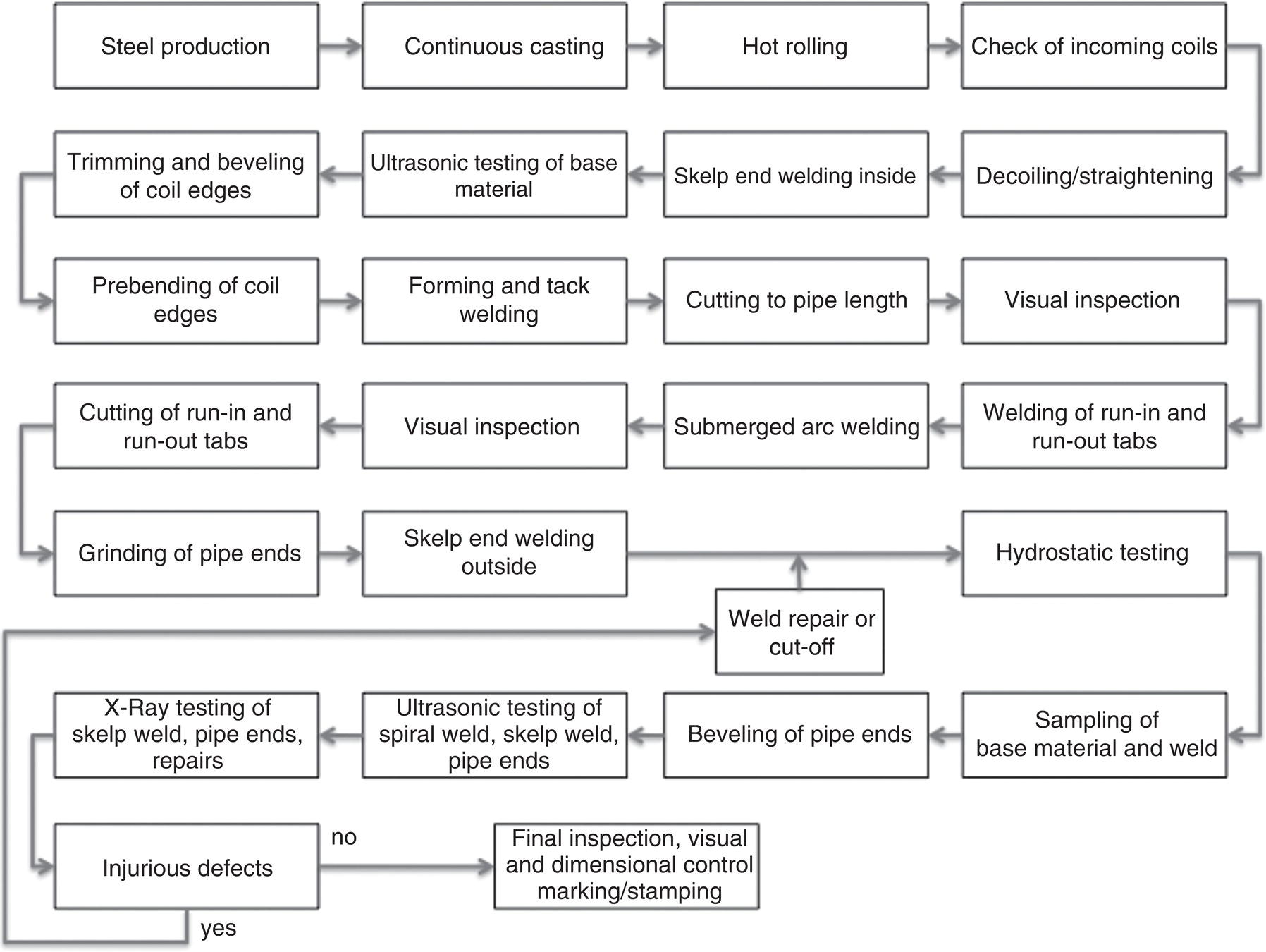
Franz Martin Knoop Technical & Scientific Solutions GmbH, Germany Spiral welded pipe was first introduced on an industrial basis in the United States in 1880 [1], but the technology used for pipe production today traces back to 1960s when submerged arc welding (SAW) became applicable and new pipe forming machines were made available. The terms spiral welded pipe and helical seam pipe are considered interchangeable and generally used for spiral formed line pipe with a single helical weld seam. Nowadays spiral welded pipe is used in gas and oil pipeline projects all over the world. The progress in steel and coil processing combined with the technological development in pipe production and quality control has pushed the use of this product for the transport of gas and oil. Despite this, the predominant portion of large diameter pipes produced all around the world for gas and oil pipelines greater than 20 in. is produced as longitudinally welded pipe. Compared to UOE-mills, the capital costs of a spiral pipe plant are very low. Also, the versatility of the process to produce a wide range of pipe sizes with a small range of steel coil width has pushed the construction of mills all around the world. The politically driven desire for local pipe manufacturing facilities in combination with the growing availability of high-quality line pipe steels is another reason for the growing acceptance of this type of pipe. As a consequence, a major part of the existing plants is characterized by very simple techniques for manufacturing and testing not being suitable for the production of high-pressure pipelines. Consequently, the pipeline operators have many reservations against this type of pipe or they even refuse completely to use this type for pipeline projects. Therefore, it is a commonly held perception that spiral line pipe is an inferior product. The opinions are mostly based on anecdotal evidence, poor experience from more than 30 years ago or poor experience with inferior pipe produced by mills with inadequate equipment and manufacturing procedures [2]. The production of spiral welded pipe follows one of two process routes commonly referred to as “one-step” and “two-step” [3]. In both routes, the steel coil, known as “skelp,” is unwound and then formed into spiral-seamed pipe. Heavy plate material has also been used in the past due to the limited availability of heavy gauge coils but is not an option anymore. The forming process of helically welded large diameter pipes generally consists of three main forming steps: The produced pipe diameter (D) depends on the helix entry angle (α) at which the material enters the forming unit and the width (B) of the hot-rolled coil (Figure 18.1). Theoretically, an angle α between 15° and 73° can be used based on actual standards with theoretical coil width between 0.8D and 3.0D [4]. In practice, the working range in most pipe mills is less than this. Coil width produced by modern hot rolling mills today range between 1200 and 1800 mm. With increasing coil width, the productivity of the process is increased and the weld seam length is reduced. It is important to mention that during forming the skelp can be over or under bend with the circumference too tight or too loose and finally resulting in residual stresses in the pipe [5]. These stresses can result in opening or closing of a formed pipe ring when cut in longitudinal direction after forming. Depending on the adjustment of the three-roll bending system, different forming strategies can be realized. It is possible and necessary to reduce and minimize such residual by optimizing the initial forming set-up. Low residual stresses present in the final welded pipe are essential for an optimized pipeline construction and when the pipe is used for sour service. Also, the pre-bending of the skelp edges needs careful control in the forming process to avoid peaking of the weld and the adjacent areas on the pipe body. Peaking of the weld seam and the coil edges can dramatically reduce the fatigue resistance and the number of pressure cycles in operation [6]. Figure 18.1 Principle scheme of spiral pipe forming. (With permission of Mannesmann Grossrohr GmbH.) In the one-step process, the coil is leveled and uncoiled by a straightening device. The leading end of the incoming coil is welded to the trailing end of the foregoing coil. This can be done by SAW or other welding methods, depending if the skelp end weld keeps an integral part of the final pipe or if the skelp weld will be cut off. First the coil edges are trimmed or milled and then, after prebending of the edges, the steel passes through a roller bending machinery to form a cylindrical pipe. The formed pipe is joined by SAW internally at the point where the skelp edges first come together, and then after half a revolution, externally, also by SAW. A typical layout of a one-step mill is shown in Figure 18.2 and process steps are described. The principle of the helical two-step (HTS) manufacturing process is shown in Figure 18.3. For this method, production is split into pipe forming combined with continuous tack welding and internal and external SAW on separate welding stations. In the first step, the hot-rolled wide strip is formed into a pipe in the pipe-forming machine and continuously tack welded. This forming unit consists of a three-roll bending system with an outside roller cage as illustrated in Figure 18.4. The function of the roller cage is to set the pipe axis and guarantee the roundness of the pipe. In the forming unit, the converging strip edges of the pipe are joined using shielded gas metal arc welding. As the continuous tack welded pipe then leaves the forming machine, a plasma cutter—moving with the tube—cuts the individual lengths required by the customer. The tack welding is done automatically and typically done by means of a laser guided weld head. To optimize the pipe and weld gap geometry, the run-out angle is also permanently controlled and adjusted by an automatic gap control system. Any change in the coil width because of the variations in the coil dimensions before or after milling does not affect the final pipe geometry. Figure 18.2 Two-step spiral welded pipe manufacturing process [7]. (With permission of Mannesmann Grossrohr GmbH.) Figure 18.3 Pipe forming and tack welding [7]. (With permission of Mannesmann Grossrohr GmbH). Figure 18.4 Submerged arc welding of the spiral weld [7]. (With permission of Mannesmann Grossrohr GmbH.) The formed and continuously tack welded pipes are then subsequently fed into separate off-line welding stands for final computer-controlled internal and external SAW with multiple wire systems. Two to four wires are used internally, with up to three wires externally. Using special roller tables, each pipe rotates with a precise screw-like motion while the SAW is carried out—first internally, then externally (Figure 18.4)—using the multiwire technique. A laser-controlled seam tracking system guarantees exact positioning and optimum overlapping of the weld seam. The tack weld carried out during the pipe-forming stage serves as a backing for the weld and is fully remolten. The use of laser controls combined with precise gearboxes and electric motors for the pipe movement ensure low tolerances on the weld geometry (e.g., good penetration and minimized misalignment). It is also state of the art in two-step mills that all welding operations are computer controlled and continuously recorded. The two-step process offers qualitative and economic advantages. Due to splitting of pipe forming and SAW, the forming speed can be increased up to 15 m/min. Exact geometrical tolerances are achieved by concentrating on the pipe geometry within the pipe forming machine—and this without being influenced by the SAW process. Thus, the process-automated technique for carrying out the subsequent SAW of the pipe—which is already tacked to be dimensionally stable—is used with a consistently high quality and without being influenced by pipe forming. The advantages of the HTS-process compared to the conventional spiral process are manifold: Pipe geometry weld seam productivity and costs The same welding methods, welding consumables, and even the same software tools and quality controls used in modern UOE-plants are also used in the two-step process. In terms of process control, the forming process and the pipe geometry can be controlled and documented in-situ. Another particularity of spiral pipes is the so-called skelp end weld. They may or may not be accepted by the purchasers, and some pipe mills use the skelp end weld sections for testing [8]. In contrast to manual welded skelp welds, high quality skelp-end welds to be used as integral part of the pipes are completed as double submerged arc welds with the first welding step performed before pipe forming and the second welding step on the outside of the individual pipe after other welding and cutting operations. In particular, for pipes with high single weights, the customer’s acceptability of the skelp end weld can be essential for the commercial efficiency and yield of this process. The same welding consumables used for the helical seam shall be also used for the skelp end welding. Also, computer-assisted welding controls and recording of weld parameters are applied from the beginning. Thanks to the similarity of the welding process, the structure and the quality assessment of this skelp end weld are equivalent to the spiral weld. The same usage factor can be applied for pipes with helical seam only or combined with a skelp end weld. Fatigue tests performed on spiral welded pipes exposed to dynamically pulsating stress demonstrate full equivalency for spiral and longitudinal submerged arc welded pipe, if forming and welding controls and limits are carefully defined and guaranteed during pipe production [6, 9]. Steel quality and composition make a major contribution to the quality of spiral welded pipe as they do for UOE pipe. However, steelmaking, from the liquid product, through casting and rolling to final coiling, is a complex operation with many variables, which is within the control of the steel production rather than the pipe production. Nevertheless, the pipe manufacturer and his clients need to be confident that the material supplied will give an appropriate pipe quality. Strict test requirements necessitate that each pipe is tested with regard to its usability by means of extensive individual tests (e.g. hydrostatic, ultrasonic, X-ray testing, visual and geometrical inspections). Material properties, like strength, toughness, hardness, and ductility, are tested in specified intervals according to standards and/or project specifications during the manufacturing process. For all welding operations throughout the production of spiral welded pipe, the welding parameters need to be monitored and adjusted to ensure defect free welds with adequate penetration optimized bead shape and height. State-of-the-art mills prepare documents about testing facilities and quality systems in which all process, production, and testing steps are detailed for each individual pipe length. Typical process flows for a conventional spiral pipe mill and for a two-step (offline) mill are shown in Figures 18.5 and 18.6 respectively. In case of the two-step process, all welding and testing steps for pipes with skelp end welds are included. Although variations of these idealized process flows can be found in existing mills around, a comprehensive traceability up to the steel making must be assured with full data acquisition and storage (electronic pipe log) along the complete manufacturing and testing route. Figure 18.5 Production and test flow in a conventional spiral pipe mill. Figure 18.6 Production and test flow in a two-step spiral pipe mill. Pipes shall be identifiable through all stages of manufacture and testing up to final inspection by the pipe production number on the pipe. With the pipe production number, the commission number, the coil number, and the heat number(s), which are recorded on the pipe record card or in the electronic data processing system full traceability is maintained from the end-product through all stages of fabrication to the melting of the base material (steelmaking, casting, and hot rolling). On completion of the final inspection, each pipe may additionally receive a shop inspection number which is also recorded in the electronic data processing system and in the final certificate. The dimensions of spiral-weld pipes are continuously adjustable, so that any diameter, as desired by the customer, can be produced from a base material of the same width. Unlike the longitudinal-weld pipe, it is not necessary to use a large number of forming tools for the various separate sizes. Spiral welded pipes are manufactured in steel grades from API 5L Grade B—X80 and to various other national and international standards. The size capability of each mill will depend upon the forming and welding capability, and the grades of steel used. Spiral welded pipe can be produced in diameters up to 120″ and in wall thicknesses up to 25.4 mm, depending on the client request. Some pipe manufacturers using the one-step process can produce pipe for piling or water service in sizes up to or in excess of 2540 mm (100″). The limiting dimensions arise from forming restrictions and the strip width. For oil and gas service the typical diameter range is 20–56 in. with 7–20 mm wall thickness. Spiral welded pipe of suitable quality for both sweet and sour oil and gas service is currently available. It is, however, necessary to draw a distinction between pipe mills with facilities, quality controls, and experience needed to produce such pipe, and those, which are only capable of producing low-grade pipe for water supply and construction applications. Spiral welded pipe has been used for gas transmission pipes in Europe and North America since decades, but recent projects in the USA and China have clearly demonstrated the competitiveness of this type of pipe. The Cheyenne pipeline project and the REX-pipeline in the USA or the 2nd West-East Gas Pipeline in China are excellent examples of this development. Also, the willingness to use X80 spiral pipes for high-pressure gas pipelines has generally changed from sporadically used portions for short pipeline lengths to be a real alternative for pipeline projects of greater lengths [10–12]. Even though most offshore pipelines constructed today are designed for high water depth with heavy gauge plate materials, spiral welded pipes become increasingly attractive as more shallow water offshore projects are planned and the technical and cost advantages are recognized [13–15]. The use of spiral welded pipe in sour service applications has been very limited due to negative experiences with inadequate sour service resistance in operation. Failures have been reported by Canadian pipeline operators but also in Mexico and Saudi Arabia [16]. Provided that stable process conditions during continuous casting, hot rolling, pipe forming, and welding are guaranteed and assumed that modern steel chemistry and cleanness is used, severe sour service requirements can be fulfilled even for high strength steel grades [17, 18]. With regard to the time and cost optimized field installation of the pipes, the requirements for a good forming capability and weldability are irrevocable basic requirements. Modern thermomechanical treated pipe steels are characterized by low carbon contents and carbon equivalents as characteristic for a good weldability. Like longitudinally welded pipes as well, spiral welded pipes can be cold-bent directly on site or hot-bent within the pipe bending facility without any restrictions. Thanks to the forming process, stringent geometrical requirements and narrow tolerances on diameter, ovality, and straightness can be guaranteed for pipe ends and the entire pipe body. As opposed to longitudinally welded pipes, no cold expansion is necessary for spiral welded pipes and no difference in tolerances between pipe body and pipe ends is needed. Basically, spiral welded pipes show a preferred orientation of its weld seam and of the direction of the hot-rolled wide strip toward the main direction of the tensions acting on the pipe. The safety of spiral welded pipes is out of the question. Many comparative full-scale fracture propagation tests carried out by independent institutions show that the fracture behavior and crack propagation resistance of spiral welded pipes are at least equivalent to those of longitudinally welded pipes. More than 120 full-scale burst tests on longitudinal and spiral welded pipe carried out worldwide have been collected and compared on behalf of the European Pipeline Research Group [19]. Cold bent pipes are commonly used in pipeline construction in order to conform the pipeline to the geometry of the trench (vertical bend) or to change direction as required following the route of the pipeline (horizontal bend). Cold field bending is used for bends having a large radius and a small bending angle in gas and oil pipelines. Spiral welded pipe need can exhibit anisotropic mechanical properties with higher yield in longitudinal than in hoop direction. Also, placing the weld seam in the neutral zone as done for longitudinal pipe is not possible. Although most international engineering standards do not differentiate between spiral and longitudinal welded pipe, some recommendations based on practical experience can be given. For high D/t ratio, small bending radius and for pipe with skelp end weld a mandrel shall be used. At least one pipe diameter, with a minimum of 0.5 m, shall be left straight at either end of a bent pipe. The bending radius should be larger than a specified minimum value increasing with the pipe diameter and the bending angle at each bending step should be limited to a specified value which decreases when the pipe diameter increases [20, 21]. In situations where pipeline integrity may be a function of the geographical and additional external load action may be due to ground movement, strain-based design concepts may be considered. Depending on the area of application, significant strain demand due to different types of ground movement can take place, reflecting in specific requirements for line pipe material in terms of strain resistance capability. Quite recently, detailed investigations and full-scale testing on spiral welded and longitudinal welded large diameter pipe have been carried out. Even though materials were not specifically developed for strain-based applications, all pipes exhibited a good behavior in terms of strain capacity and critical curvature at buckling onset and demonstrated to be suitable for SBD applications [22–25].
18
Pipe Manufacture—Spiral Pipe
18.1 Manufacturing Process

18.2 Quality Control Procedures
18.3 Range of Grades and Dimensions
18.4 Typical Fields of Applicability
References