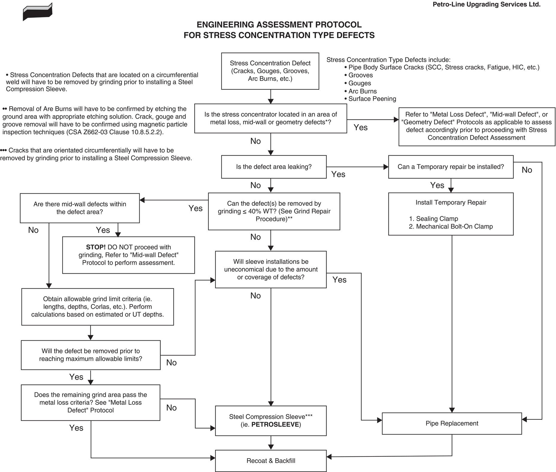
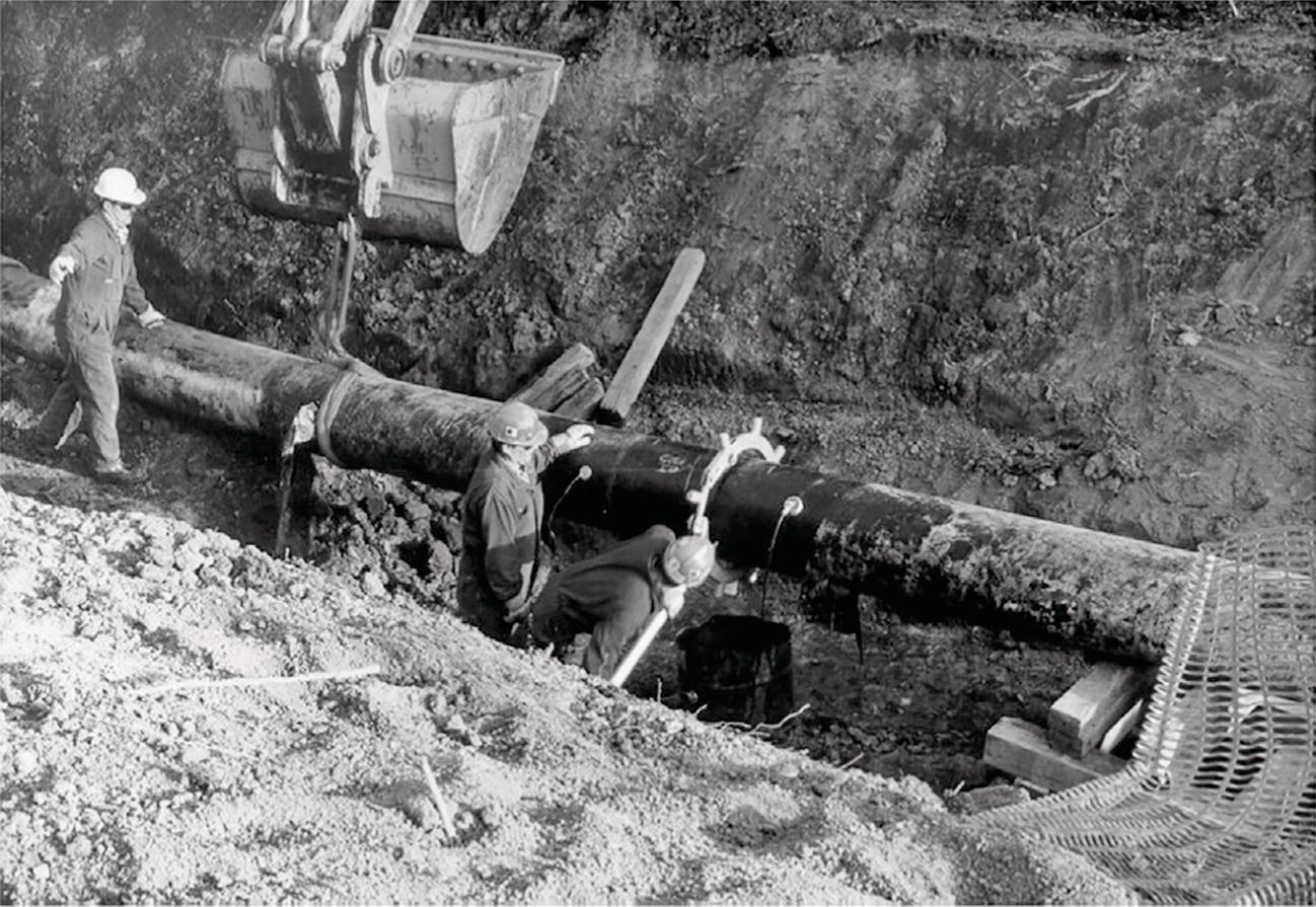
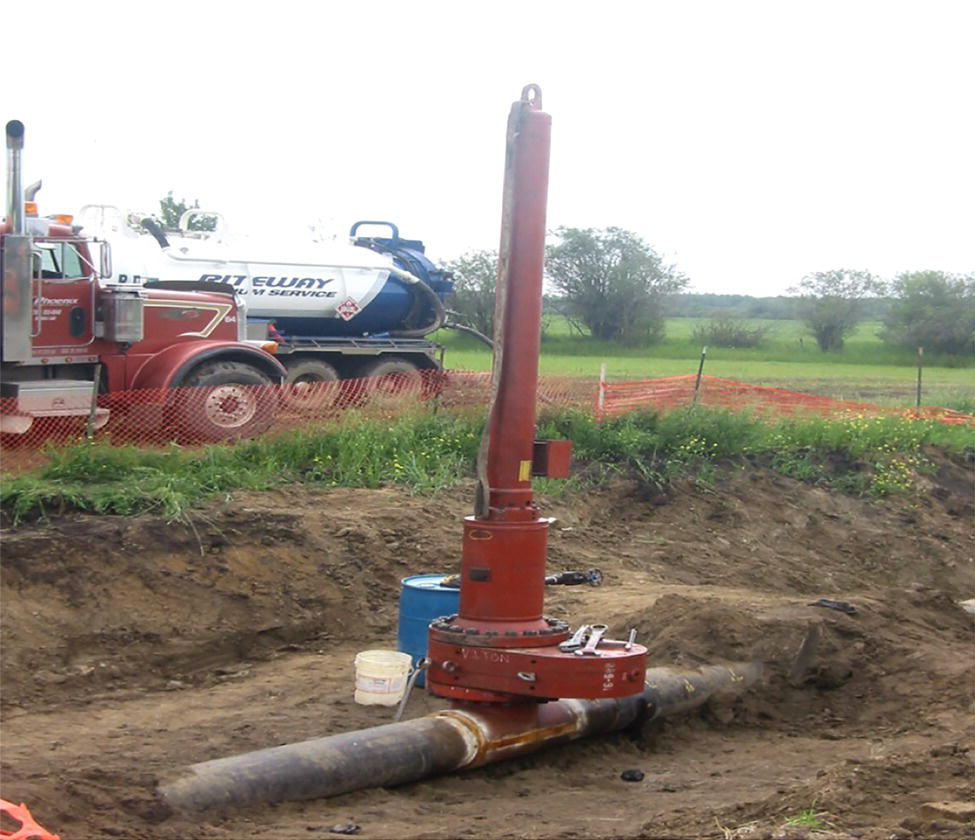
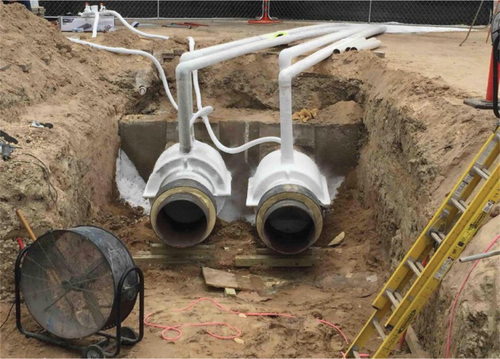
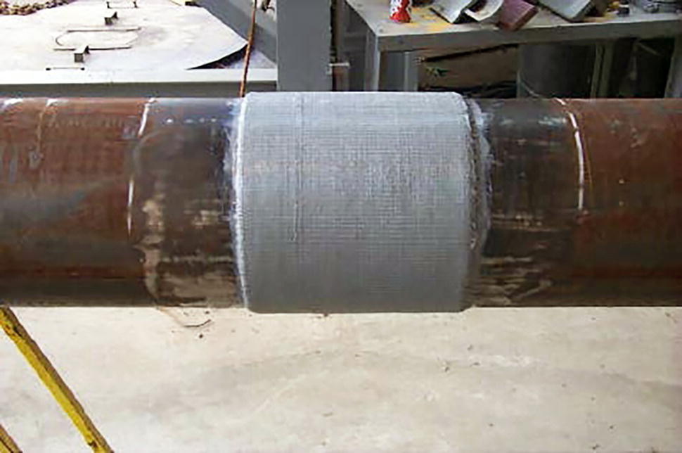
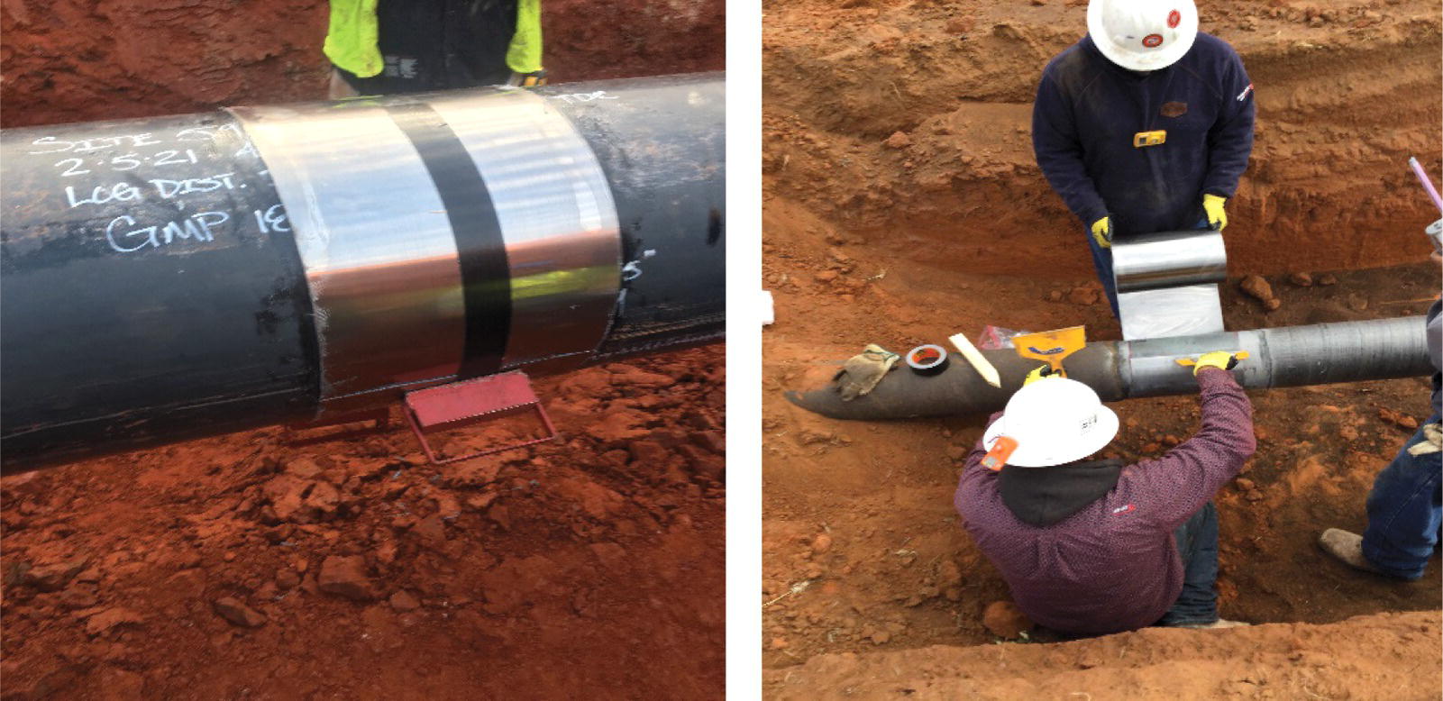
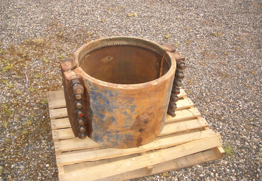
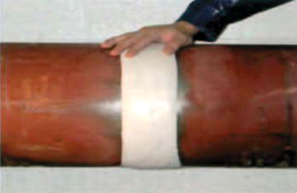
Robert Smyth1 and David Futch2 1Petroline Construction Group, Nisku, Alberta, Canada 2ADV Integrity, Inc., Houston, TX, USA This chapter considers various pipeline repair techniques. Because of the many options available, it is the responsibility of the operating company to review the various options and select the option that provides the best result for their situation. The technical merit of each repair system should be considered first and foremost. However, other practical considerations should also be considered, such as availability of the repair system and availability of qualified individuals installing the repair. Common types of flaws, as presented by Table 10.2 CSA Z662 [1], that affect the integrity of an operating pipeline, include external and internal corrosion, stress corrosion cracking (SCC), manufacturing flaws including seam weld flaws/cracks, construction flaws including arc burns, and third-party damage including dents and gouges. In addition, any of these flaws can eventually result in a leak. Each individual flaw may require a specific repair technique. Once the need for repair has been established, various repair methods can be used. This chapter covers the repair of pipelines via methods outlined in industry codes such as ASME B31.4, ASME B31.8, and CSA Z662. Some of these repair methods are pipe replacement, grinding, steel sleeves (Type A, Type A compression, Type B, thin sheet steel coil wrap), epoxy-filled sleeves, composite reinforcement sleeves, hot tapping, direct deposition welding, and mechanical clamps. Repairs should only be undertaken with reference to the appropriate industry standards and jurisdictional regulations, with individuals who are trained and qualified for the technique being used. When undertaking a repair, the objective is to return the pipe to its’ original integrity. Following the repair, the excavation then can be backfilled and surface reclaimed. This repair can be accomplished by using many of the available options listed below: Repair techniques can be further grouped into two repair types, pressure reinforcing and pressure containing. Pressure reinforcing repairs include repairs such as Type A steel sleeves and composite repairs. Pressure containing repairs include repairs such as Type B steel sleeves for permanent and mechanical clamps for longer term temporary leak repairs. Pressure containing repairs are typically specified for those features that can grow through-wall over the life of a repair, such as internal corrosion that has not been arrested, and unstable crack-like indications. Indications requiring repair can be located through in-line inspection (ILI) tools, direct examination (such as ECDA, ICDA, or SCCDA), or in some cases, observing physical evidence (such as pooling product from a leak). Following an ILI inspection run, the signal log is analyzed to identify the severity and location of the indications. Although, over time, the accuracy of log information has greatly improved, the actual determination of the severity of the defect is only known after the pipe has been excavated, the pipe/defect cleaned, examined, and an engineering analysis completed. For safety reasons, it is advisable for the pipe operating pressure at the inspection site to be reduced during the excavation, NDE examination, and repair procedures. Industry guidance suggests operating pressure reduction to 80% of that pressure that the site has been exposed to within a recent time frame. This criterion simulates a typical pressure test, where the recognized safe operating pressure is calculated as 80% of the test pressure. Pipeline operators should have corporate written standard operational procedures describing available repair methods for all common defects. Then, when an integrity program is undertaken, these repair procedures are available to the inspector/contractor. Prior to commencing a repair program, the operating company needs to develop repair criterion for use in the program. This criterion would specify what indications are acceptable, only needing to be recoated, and what indications needed to be repaired. The defect acceptable/repair criteria would consider such items as local environmental factors, public risk, safety factor (burst pressure as a percentage of SMYS), and lastly operational concerns. Following this analysis, a protocol could be developed to convey the corporate requirement to the field. A typical protocol for dealing with stress concentrators is presented in Figure 43.1. Protocols for various indications are used for providing guidance to the field crews in making decisions. This can reduce the overall cost of an integrity repair program. When determining the serviceability of a defect, both the current and future pressure requirements need to be considered. Potentially, the simplest repair technique is applying a new coating to the area of pipe inspected. The pipe can be examined via nondestructive examination once excavated and the original coating removed. All the features then can be identified and compared to the corporate criteria. If a feature is not injurious, the area can be recoated and backfilled. In the process of recoating, the mechanism of future growth should be eliminated (such as external corrosion). Application of new, high-integrity coating systems will help prevent future corrosion from occurring. A method to match the new coating to the old coating should be provided to the contractor. Cutout and replacement is the ideal repair method for all defects. However, taking into account economics (e.g., loss of natural gas, taking line out of service), other repair techniques described later can be utilized. Pipe replacement involves the removal of the affected pipe and installing a new, pretested pipe section. A suggested minimum permissible length [1] of replacement pipe is When undertaking this work, an applicable welding procedure must be used that considers welding the old pipe to the new pipe as well as using welders who have been tested to the procedure. In addition, usually, the original pipe has developed magnetism that must be mitigated prior to commencing welding. An electrical connection across the intended cut must be provided in order to prevent sparking during the cutting process. It is common to use the same or stronger material strength and a similar wall thickness in the replacement pipe compared to the surrounding pipe. However, when a thicker pipe is used for the replacement, the change in wall thickness must be mitigated by tapering the inside of the thicker pipe. Engineering calculations need to be performed to confirm that the tapered portion of the replacement pipe has the pressure containing properties of the adjacent pipe. Figure 43.1 Engineering assessment protocol for stress concentration type defects. (Courtesy of Petro-Line, Inc.) All replacement pipe needs to be pressure tested to the same level as the original pipe. This pressure test usually is performed at a separate location. Prior to cold cutting the pipe (shown in Figure 43.2), the cut location needs to be evaluated. The potential cut location should be examined for laminations, significant ovality, or other injurious features that may affect the subsequent tie-in weld. In the event, injurious features are identified, a second cut location needs to be located. Prior to cutting, the product needs to be removed, e.g., by performing a nitrogen purge. In this case, the product between the two shut off valves could be swept clean by sending a pig from the upstream valve setting to the downstream setting using compressed nitrogen. When the pig arrives at the downstream valve, the nitrogen pressure is then released, leaving a safe, empty pipe section of inert gas. Another method to remove product from the defect location would be to create an isolation of the to-be-cut out section by welding stopple fittings [2] to the pipe upstream and downstream of the defect. The pipe between the stopples can then be isolated and evacuated of product. If required, an optional by-pass line can be installed to maintain pipeline operation independent of the isolated pipe. The welding requirements for stopple installation (Figure 43.3) are explained in Chapter 42, “Pipeline Repair Using Full-Encirclement Repair Sleeves.” In addition, other isolation options have been employed, including a freeze plug (Figure 43.4) or setting an internal pig. When pressure testing with water and a rupture occurs, freeze plugs [3] can be used to prevent the water on both sides of the rupture from entering the site while a new section of pipe is being welded into the line. With freeze plugs, liquid nitrogen or CO2 assemblies can be placed upstream and downstream of the location being replaced, keeping the water in the pipe from interfering with the welding. Figure 43.2 Cold cutting the pipe. (Courtesy of Petro-Line, Inc.) Figure 43.3 Stopple installation. (Courtesy of R.J. Smyth.) Figure 43.4 Freeze plug. (Courtesy of Innovator Industrial Services.) Also, there are internal pig assemblies that can be engaged within the pipe creating a plug. These are particularly functional when undertaking a cut-out of an operating pipeline. Two pigs could be launched with a distance between them. When they arrive at the cut-out location, line operation would stop, the pigs would be set, product in the cut-out area removed, and cold cutting of the pipe undertaken. For all isolation options, detailed engineering analysis must be undertaken to evaluate the isolation process, success probability, and the long-term effect on the pipeline. Following completion of the tie-in welding of old to new pipe (shown in Figure 43.5), the welds are nondestructively inspected for flaws. The tie-in weld may have to be repaired in the event flaws are identified larger than that allowed by the appropriate code and standards. The replacement pipe then is coated. At the interface between the new coating and the old coating, an appropriate coating technique needs to be used to bridge the coating types. If one of the plugging techniques is used, such as stopples, freeze plugs, or internal plugs, the construction equipment would be removed prior to the new pipeline section being brought into service. Figure 43.5 Completing the tie-in weld on a cut-out. (Courtesy of Petro-Line, Inc.) During backfilling, the pipe needs to be supported so that no additional bending moments are applied to the pipe by the soil. When cracking is identified on the pipe surface, grinding to remove the crack can return the pipe to an acceptable integrity condition. Grinding, if successful, will remove the stress concentrating crack tip, thus converting the defect into a metal loss situation. In this case, various engineering analyses can be utilized to determine the acceptable maximum amount of steel that can be removed. This engineering analysis should consider both the current and future operation requirements of the pipe section. In Figure 43.6a, SCC is illustrated. The repair, after removal of the cracking by grinding, is shown in Figure 43.6b. Prior to commencing the grinding/sanding operation, an engineering analysis needs to be completed to determine a safe working environment. The steel properties, wall thickness, crack depth, and internal pressure would be considered. In particular, the maximum crack depth needs to be determined, as well as the maximum amount of steel that can be removed, prior to commencing the grinding operation. Figure 43.6 (a) Illustration of a SCC defect and (b) grind repair. (Courtesy of Petro-Line Inc.) Following the complete removal of the cracking, a final analysis usually is completed to determine the theoretical burst pressure of the pipe at the grind location. This analysis, again, should consider the current and future use of the section as well as any potential pressure testing. A subsequent repair may be required if the burst pressure analysis results in a condition that the integrity of the repair location is less than the integrity of the adjacent pipe. In this event, the defect would be considered external wall loss, like corrosion. There are two basic types of tight-fitting full-encirclement steel sleeves, Type A (shown in Figure 43.7) and Type B (shown in Figure 43.8). The primary function of both types is structural reinforcement of the defective area. However, a Type B sleeve is also pressure containing. Both Type A and Type B sleeves contain a longitudinal weld that does not touch the pipe. A Type B sleeve requires a circumferential fillet weld at both ends of the sleeve to provide pressure containment. Figure 43.7 Typical Type “A” steel sleeve. (Courtesy of R. Smyth.) Figure 43.8 Typical Type “B” steel sleeve. (Courtesy of Petro-Line Inc.) These repair types (Type A and B) are further described in greater detail in Chapter 42, “Pipeline Repair Using Full-Encirclement Repair Sleeves.” British Gas developed a variation of the sleeve repair concept in the form of their epoxy filled sleeve [4]. In this case, the shell is a steel sleeve with a significant annular gap from the carrier pipe. The system ensures structural support to the defect and has a wide tolerance for repair of complex or distorted pipe geometries. The two sleeve halves are assembled around the pipe, followed by completing two longitudinal welds. After the two longitudinal welds have been completed, the steel cylinder is centralized around the pipe such that the space between the cylinder and pipe is equalized. The annular gap at each end of the sleeve is sealed with an epoxy. Following the curing of the epoxy seal, an epoxy grout (e.g., a high-stiffness epoxy/sand mixture) is pumped into the annular space from the bottom, until it flows out of an overflow hole at the top of the sleeve. Once the epoxy filler has hardened, the pipe and defect are restrained by the epoxy/steel shell. Type A compression sleeve is a variation of a Type A sleeve. They are designed so that the repaired section of the carrier pipe is maintained in a compressive hoop stress condition during subsequent pipeline operation. This repair technique is suitable for all defects except leaking defects. It should not be used over tight radius bends. In addition, this approach is attractive for repairing longitudinally oriented crack-like defects, such as SCC. By eliminating the tensile hoop stress, the driving force at the crack tip is eliminated. Steel compression sleeves involve assembling two sleeve halves over the defect area and drawing them together using jacking devices. The sleeve halves are then heated to a specified temperature, and then welded together using conventional welding techniques. Epoxy filler is used between the carrier pipe and sleeve to achieve the transfer of stresses and to act as a sealing agent to prevent moisture from entering between the pipe and sleeve. PetroSleeve™ (Figure 43.9) is a commercial product that was developed to install a steel repair sleeve while the pipeline remained in operation, to not weld to the pipe, and to have the carrier pipe remain in a compressed state for all operational pressures. Because the carrier pipe remains in a compressed state, the sleeve/pipe/epoxy bond remains intact. Comprehensive testing [5] has demonstrated that the fillet weld design is suitable for use on pipelines that experience significant pressure cycling. Quality control procedures for this technique involve monitoring sleeve temperature during the heating process and verification of the achieved carrier pipe compression. Nondestructive inspection of the completed welds is performed after welding. Figure 43.9 Example of an installed 36″ PetroSleeve™ Compression Sleeve. (Courtesy of PetroSleeve.) Various fiber reinforced plastic (FRP) composites have been developed for applications in a range of industries including transportation, chemical, and both the upstream and downstream sectors of the oil and gas industry. Composites have found this diverse usage because they can be specifically designed to provide the mechanical properties required for the application. This, along with a high strength-to-weight ratio, has made composites the best choice for many critical applications in advanced equipment. Composite repair systems work by constraining a defect as it bulges. As the internal pressure of the pipe rises toward the line maximum operating pressure (MOP), the pipe wall elastically stretches. Pipelines are designed never to exceed 80% of their elastic limit. Therefore, plastic deformation is only possible if the wall gets thinner, for example, through corrosion. All properly designed and installed composite repairs work to constrain this elastic/plastic distortion of the pipeline and prevent this thinner wall ligament from bulging beyond its failure limit. There are two broad groups of composites available on the market, a “composite sleeve” rigid coils and a wet lay-up (Figure 43.10). Wet lay-up composite repair systems allow for better contour to the pipe surface when compared to a rigid coil, allowing for the repair of features coinciding with bends or elbows on a pipeline. Within both ASME B31.4 and B31.8S, composite sleeves have acceptance for the repair of wall losses of up to 80%. Standards, such as ASME PCC-2 Article 4.2 and ISO PDTS 24817, are typically used to design wet-wraps and allow the material properties of a composite to be estimated based on short-term test data. Equations 9 and 10 of ISO PDTS 24817 are the only equations in ISO PDTS 24817 which use long-term test data to establish the long-term strength of the composite repair to ensure that it will remain strong enough following the required number of years of service. Figure 43.10 Installation of wet lay-up composite wrap. (Courtesy of Armor Plate Inc.) FRP composites use various resin formulations including polyesters, epoxies, and vinylesters. Each of these resins has unique characteristics of cost, compatibility with reinforcing fibers, chemical resistance, strength, and moisture absorption. As an example, rigid isophthalic polyester resin has seen years of service in composite gasoline storage tanks buried in soil environments similar to that of pipeline service. It has low moisture absorption, excellent resistance to chemicals, and good thermal properties making it suitable for most pipeline applications. Three characteristics must be considered when designing fiber reinforcement: There are a number of commercially available reinforcing fibers with various chemical and mechanical properties, including E-glass and carbon fiber. The most common fiber type used for the reinforcement is E-glass. E-glass was selected for the use in the Clock Spring® because of its high-strength, electrical properties, availability, and compatibility with the selected resin. E-glass is a super-cooled mixture of metallic oxides. It is brittle and transparent but has very high tensile strength, 3400 MPa (500 ksi). These filaments are bundled together into tows. Each of the tows contains 4000 filaments. Following processing and handling operations, the effective tensile strength is generally about 1700 MPa (246 ksi). Carbon fiber composite repairs have a higher modulus when compared to E-glass. The higher modulus allows for faster, more effective loading of the composite repair. A higher modulus also results in a higher stiffness repair, which enables the repair of more severe defects. A significant amount of research has been conducted in the past 5 years in the use of carbon fiber systems in the reinforcement of crack-like indications. The higher stiffness helps to restrict crack growth effectively in a feature susceptible to cyclic hoop loading. Reinforcement can be oriented longitudinally in a structural element, transverse to the longitudinal direction or in any direction desired by the designer. Fiber direction can be so varied that virtually isotropic material can be produced. Chopped Strand Mat (CSM) is a very common form of fiberglass used in many applications. The randomly oriented, short strands of glass intertwine to form the bed of the material. The resin then binds these strands together. The strength of the mat in any given direction is unpredictable and relies largely on the strength of the resin. CSM should not be used for applications requiring critical, long-term reinforcement required in a specified direction. Swirl Mat is similar to CSM except the fibers are longer and generally laid in a circular or swirl pattern. Like CSM, it is not suitable for high-strength reinforcement applications like pipeline repair. Unidirectional rovings (tows) can be used directly in composite manufacture or they can be converted to other forms, such as a glass cloth with various weaves. Cloth made from E-glass is easy to use in the manufacturing process but is not as durable as unidirectional glass. The weave in the cloth introduces a path for moisture and reduces the modulus of elasticity. For high-pressure pipeline repair applications, unidirectional alignment of the reinforcing glass has proved to be the most effective and durable architecture. Fiber direction can be so varied that virtually isotropic material can be produced. Cloth weaves have very low initial strain resistance until the fibers in the principal strain direction are straightened and begin to carry more and more strain from the increasing internal pressure. Unless the internal pressure is significantly reduced during the repair, the load carrying fibers in composite weaves will only be in partial tension. For high-pressure pipeline repair applications, unidirectional alignment of the reinforcing fibers has proved to be the most effective and durable architecture to restore containment of the hoop stress. In the thin sheet steel coil wrap repair method, thin steel is wrapped around the pipe in multiple revolutions (shown in Figure 43.11). The number of required layers follows ASME PCC-2 Article 4. The layers of steel are secured by an adhesive system. High modulus filler material is utilized to fill in metal loss or around any protuberances. The thin steel (typically 0.025 in.; 0.65 mm) conforms well to out of round conditions. Figure 43.11 Installing steel coil wrap. (Courtesy of Pipe Spring.) Defects can be removed using the hot taping process. The full defect being removed should fit within the capacity of the equipment. Therefore, this method is not feasible for long defects or defects progressing around a large percentage of the pipe’s circumference. To accomplish this repair, a fixture (e.g., a stopple fitting) is welded to the pipe, encircling the defect. The specialized flange on the stopple fitting is machined to accommodate a plug that can be secured externally for the “stopple operation.” Following the hot tapping process, a plug is inserted in the flange using the stopple equipment and a blind flange is installed to secure a pressure seal. Using this process, the defect is removed from the pipe and can be examined. Welding procedures are required for this process, as described in Chapter 42, “Pipeline Repair Using Full-Encirclement Repair Sleeves.” Direct deposition welding is a process whereby the defect is repaired or filled by weldment on the pipe. Significant engineering and procedure development is required to design an appropriate welding procedure for the application. In some jurisdictions, this technique is allowed only in nonsour natural gas pipelines, and the defect is not on a dent, situated on a mill seam, or circumferential weld and the remaining wall thickness at the defect location is equal to or greater than 3.2 mm (0.126 in.) [1]. The welding procedures used for a direct deposition welding repair would be like the ones used for Type B sleeves, as discussed in Chapter 42, “Pipeline Repair Using Full-Encirclement Repair Sleeves.” Repair can be made using commercially available mechanical clamps [6]. The repair device usually is supplied as two halves with a bolting arrangement to mount the device onto the pipe. The ends of the clamp contain sealing elements to create a pressure containing environment around the pipe. Therefore, these clamps require a tight tolerance on the pipe shape at the sealing location. The lifespan of these repairs is typically governed by the codes and standards applicable to the pipeline. In some cases, the clamp itself can be fully welded, like a Type B sleeve. A typical “bolt-on” sleeve is shown in Figure 43.12. At each end, neoprene seals are provided so that when the bolts are tightened, a pressure seal is created circumferentially and longitudinally. After the device is installed onto the pipe, at the discretion of the pipeline owner, and based on the design of the manufacturer, the device may be welded to the pipe, effectively creating a Type “B” pressure containing sleeve. Figure 43.12 Typical bolt-on sleeve. (Courtesy of R. Smyth.) Various products are commercially available, including pin hole clamps, mechanical clamps, and composite wraps [7], to repair leaking defects, such as a pin hole. These devices are applied around the pipe (Figure 43.13) to seal or stop the leak. Following the application of these devices, a cutout or repair is undertaken at a later date. Each system will have specific acceptable pressure ranges. This repair type could require a pipeline to operate at a reduced pressure until a permanent repair is completed. Figure 43.13 Temporary repair device—Stop It® Pipe Repair System. (Courtesy of InduMar Products, Inc., Houston, TX.) Many of the systems discussed in this chapter can be used in a temporary manner. Sound engineering judgement, which considers the lifespan of the repair, is required. This should also include how to properly track the repair lifespan, so to ensure the integrity of the pipe. All temporary repairs must be either removed or made permanent in a time appropriate manner. In Table 43.1, some examples of types of defects and repair methods that can be used are listed. More detailed information on defects and their repair is available in Ref. [8]. In selecting a repair method to deal with a specific defect, whether the defect be a corrosion defect, a crack, a dent, a gouge, a weld defect, and so on, it is essential to consult the standard that is applicable in the jurisdiction where the pipeline is located. Once the repair method has been selected, it is important to follow the manufacturer’s installation instructions, including those required for surface preparation. Table 43.1 Examples of Pipeline Defects and Applicable Repair Methods Note 1: Defect must be entirely removed without penetrating more than 40% of the wall thickness. Note 2: Defect must be contained entirely within the area of the largest possible coupon of material that can be removed through the hot tap fitting. Note 3: The welding-procedure specification shall define the minimum remaining wall thickness in the area to be repaired and the maximum internal pressure during repair. Low-hydrogen welding process must be used [9]. Note 4: Tight-fitting sleeve or hardenable filler must be used to fill the void between the pipe and sleeve [9]. Note 5: Internal corrosion must be successfully mitigated. Note 6: Depth of dent must be ≤15% of pipe specified OD and dent must be filled before sleeve is applied [8]. Note 7: Defect must be entirely removed and removal verified. Note 8: Any circumferential cracks shall be removed by grinding prior to application of the sleeve [8].
43
Pipeline Repair
43.1 Introduction
43.2 Background
43.3 Defect Identification
43.4 Safety
43.5 Protocols
43.6 Recoat
43.7 Pipe Replacement
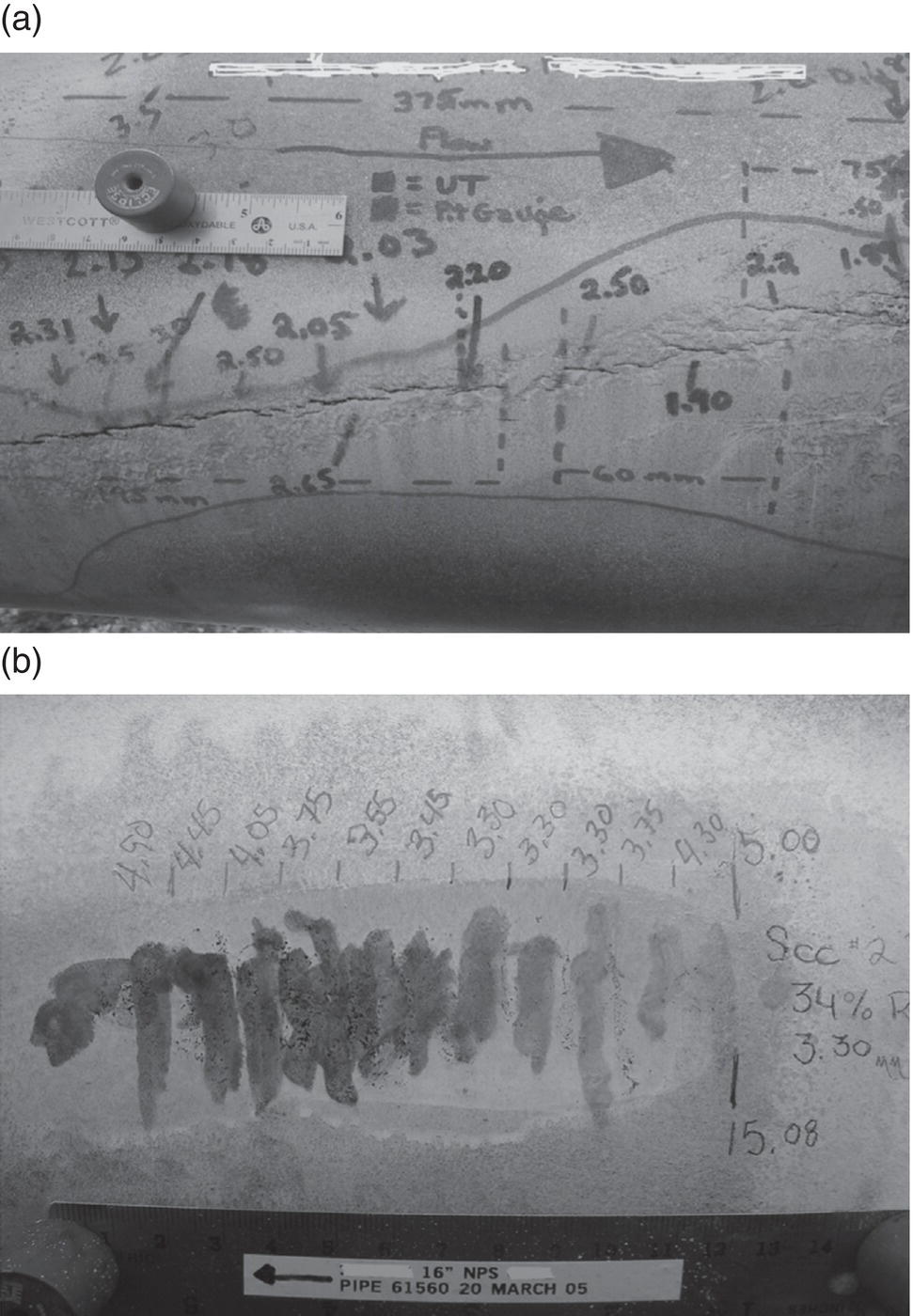
43.8 Grinding/Sanding
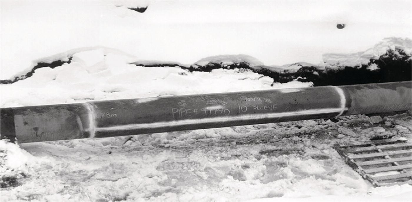
43.9 Full-Encirclement Steel Sleeves, Type A and B

43.10 Epoxy Filled Sleeves
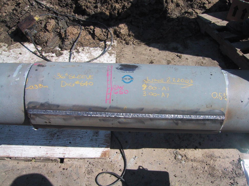
43.11 Steel Compression Sleeves
43.12 Composite Reinforcement Sleeves
43.12.1 Designing an Effective Composite Repair
43.12.1.1 Resin Selection
43.12.1.2 Fiber Type, Form and Architecture
41.7.1 Fiber Type
41.7.2 Fiber Form and Architecture
43.13 Thin Sheet Steel Coil Wrap
43.14 Hot Tapping
43.15 Direct Deposition Welding
43.16 Mechanical Clamps
43.17 Temporary Repairs
43.18 Applicability to Various Defect Types
Type of Defect
Repair Methods
Pipe Replacement
Grinding
Hot Tap
Weld Metal Deposition
Sleeves
Reinforcing Type A
Steel Compression Reinforcement
Pressure Containing Type B
Composite
Bolt-On
External corrosion ≤80% through wall
Yes
No
Note 2
Note 3
Note 4
Yes
Yes
Note 4
Yes
External corrosion >80% through wall
Yes
No
Note 2
No
No
Yes
Yes
No
Yes
Internal corrosion ≤80% through wall
Yes
No
Note 2
No
Note 5
Note 5
Yes
Note 5
Yes
Internal corrosion >80% through wall
Yes
No
Note 2
No
No
No
Yes
No
Yes
Gouge, groove or arc burn on pipe body
Yes
Note 1
Note 2
No
Note 4, 7
Yes
Yes
Note 4, 7
Yes
Crack
Yes
Note 1
Note 2
No
Note 1
Note 8
Yes
Note 1
Yes
Dent on pipe body
Yes
No
Note 2
No
Yes
Yes
Yes
Note 6
Yes
Defective girth weld
Yes
No
No
Note 3
No
No
Yes
No
Yes
Hard spot
Yes
No
Note 2
No
Note 4
Yes
No
Yes
Leak
Yes
No
No
No
No
No
Yes
No
No
References