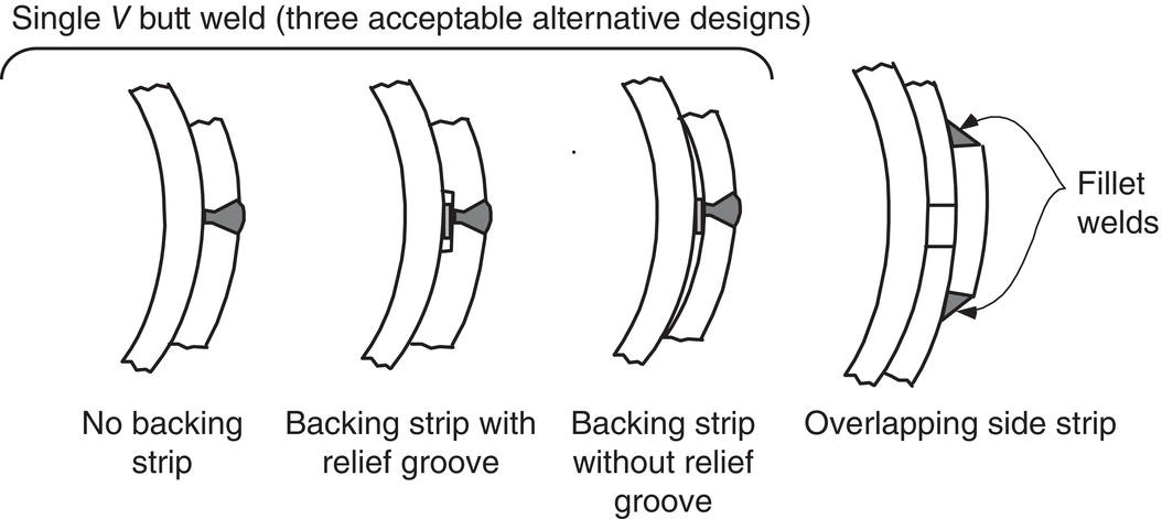
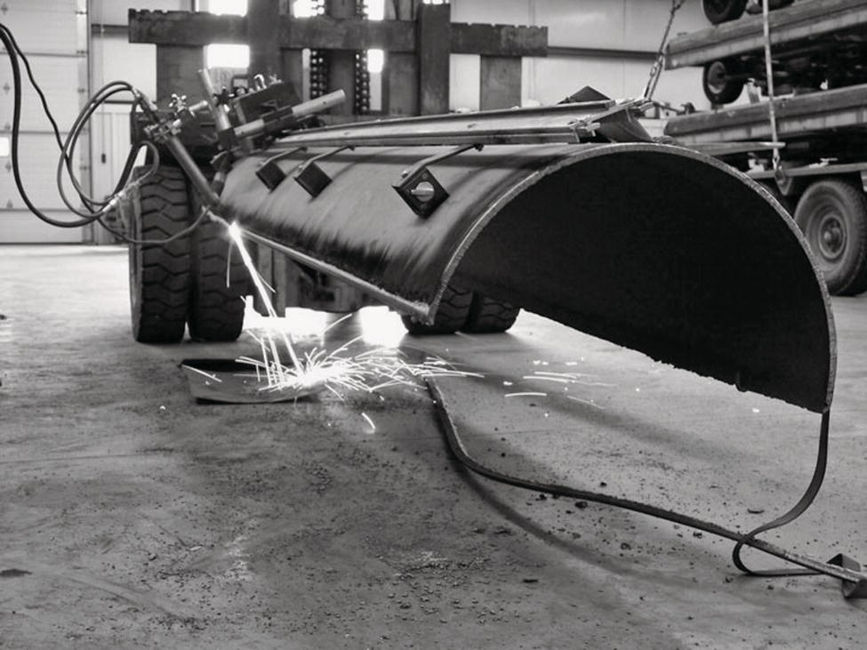
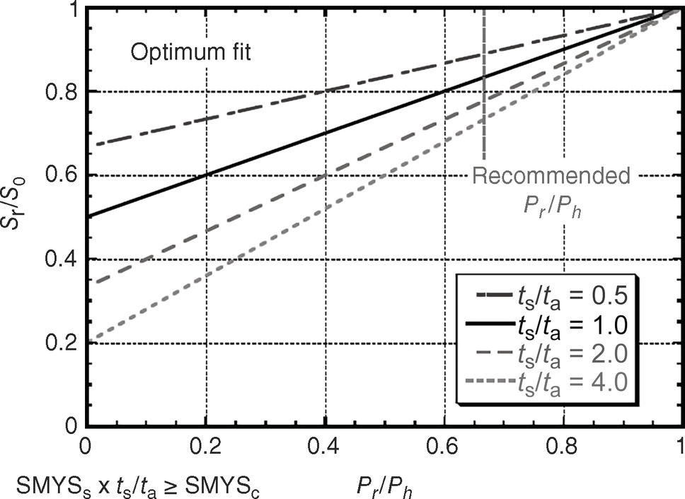
William A. Bruce1 Melissa Gould1 and John Kiefner2 1DNV USA, Inc., Dublin, OH, USA 2Kiefner and Associates, Inc., Worthington, OH, USA Damage to operating pipelines is a major concern for pipeline operators. Common types of damage include corrosion, either external or internal, mechanical damage, dents, stress corrosion cracking (SCC), and so on. External corrosion is the most common need for repair of an operating pipeline. As pipelines become older, the need for repair often increases as the result of deterioration of protective coating materials and subsequent corrosion over time. There are significant economic and environmental incentives for performing pipeline repair and maintenance without removing the pipeline from service. From an economic viewpoint, a shutdown involves revenue loss from the loss of pipeline throughput, and for gas transmission pipelines, also from the gas lost to the atmosphere. Since methane is a so-called greenhouse gas, there are also environmental incentives for avoiding the venting of large quantities of gas into the atmosphere. Once the need for repair has been established, the predominant method of reinforcing or encapsulating corrosion and other types of damage in cross-country pipelines is to install a welded full-encirclement steel repair sleeve. This chapter covers the repair of pipelines using full-encirclement repair sleeves, which is also covered elsewhere [1–3]. Advantages and disadvantages compared with other repair methods are discussed and the concerns for welding onto in-service pipelines are also reviewed, as are the approaches used to address them. To prevent an area of corrosion or other damage from causing a pipeline to rupture, the area containing the damage must be reinforced to prevent the pipeline from bulging outward. Alternatively, the area containing the damage can be encapsulated to contain any leak that may occur. The predominant method of reinforcing or encapsulating damage in cross-country pipelines is to install a full-encirclement repair sleeve. There are two basic types of tight-fitting full-encirclement steel sleeves: Type A and Type B. The primary function of both types is structural reinforcement of a defective area. Type B sleeves can also contain pressure. There are also various encapsulation type sleeves, the primary function of which is to contain pressure without providing structural reinforcement. While Type A sleeves can be installed without welding to an in-service pipeline, the ends of Type B sleeves must be welded to the pipeline to contain the pressure. There are often significant incentives for avoiding interruption of pipeline service; therefore, this welding is often performed “in-service.” There are two primary concerns with welding onto in-service pipelines, whether for installing repair sleeves or installing a branch connection prior to “hot tapping.” The first is for “burnthrough,” where the welding arc causes the pipe wall to be penetrated. The second concern is for hydrogen cracking, since welds made in-service cool at an accelerated rate as the result of the flowing contents’ ability to remove heat from the pipe wall. Because the concerns are the same for welding repair sleeves and hot taps, this type of welding is often referred to as hot tap welding. The predominant method for reinforcing or encapsulating corrosion and other types of damage in cross-country pipelines is to install a welded full-encirclement steel sleeve. There are two basic types of tight-fitting full-encirclement steel sleeves: Type A and Type B. The primary function of both types is structural reinforcement of a defective area. Type B sleeves can also contain pressure. There are also various encapsulation type sleeves, the primary function of which is to contain pressure without providing structural reinforcement. The results of work that began in the 1970s [4–7] show that a properly fabricated steel sleeve restores the strength of a defective pipeline segment to at least 100% of the specified minimum yield strength (SMYS). Damaged pipe sections repaired using properly installed repair sleeves failed in the pipe body away from the repair. Type A sleeves are particularly attractive because they can be installed on a pipeline without welding to the in-service carrier pipe. Such sleeves provide reinforcement for the defective area. They cannot contain pressure and are used only for nonleaking defects. To protect the repair crew from a defect that may be on the verge of failure, they should be installed at a pressure level below that at which the defect might be expected to fail (e.g., 20% less than the pressure that was present at the time the defect was discovered). A typical configuration and weld details for a Type A sleeve are shown in Figures 42.1 and 42.2, respectively. The sleeve consists of two halves of a cylinder of pipe or two appropriately curved pieces of plate that are placed around the carrier pipe at the damaged area and after positioning are joined by welding the longitudinal side seams. As shown in Figure 42.2, the seams may be single-V butt welds or overlapping steel strips fillet welded to both halves. If the side seams are to be butt welded and the sleeve halves are to be made from the same diameter pipe as the carrier pipe, then each half should actually be just more than half of the circumference of the piece of pipe (Figure 42.3). Otherwise, the gap to be filled by butt welding will be too large. With the overlapping strip concept, it is not essential that each half actually be more than half of the circumference because the gaps can be easily bridged by the side strips. As shown in Figure 42.2, the overlapping strip is typically the same thickness as the sleeve with a full-size fillet weld. Figure 42.1 Illustration of Type A (reinforcing) sleeve. (Courtesy of Pipeline Research Council International.) Figure 42.2 Weld details for Type A sleeve. (Courtesy of Pipeline Research Council International.) Figure 42.3 Sleeve fabrication from pipe material. (With permission of ATP Welding, Inc.) One major advantage of Type A sleeves over other types of repairs is that for relatively short defects they can function effectively without necessarily being a high-integrity structural member. Relatively short defects are those whose lengths (L) are less than or equal to With defects longer than It is acceptable to use sleeves thinner than the carrier pipe if their strength is increased by an amount sufficient to compensate for their thickness being less than that of the carrier pipe (using Barlow’s formula). In a similar fashion, the sleeve could be of an acceptable material with lower strength than that of the carrier pipe if its thickness is increased to compensate for the difference in strength. To assure that adequate reinforcement exists and that the sleeve will indeed prevent a rupture, the sleeve should extend beyond the ends of the defect (i.e., onto sound, full-thickness pipe material) at least 50 mm (2 in.). Type A sleeves have some minor disadvantages for some applications. Firstly, they are not useful for circumferentially oriented defects because they have no effect on the longitudinal stress in the carrier pipe. Secondly, they cannot be used to repair leaking defects. Thirdly, a potential crevice is created in the form of an annular space between the sleeve and the carrier pipe that may be susceptible to corrosion if not sealed using an effective coating material. However, there have been no reported service failures caused by this latter potential problem. Because of this potential problem, however, some companies use full-encirclement sleeves as Type A sleeves, but weld the ends to the pipe to prevent further corrosion, thus making them essentially Type B sleeves. This practice should be avoided because of the potential concerns for welding onto an in-service pipeline. The best way to avoid welding problems is to avoid placing welds where they are not necessary. A better solution to avoiding a potential crevice is the use of an effective coating material. Since the primary function of both Type A and Type B sleeves is to prevent bulging of the defective area, this section pertains to assuring effective reinforcement. To be effective, Type A sleeves should reinforce the defective area, restraining it from bulging radially as much as possible. This applies to tight-fitting Type B sleeves as well. First and foremost, the sleeve should be installed as tightly as possible, i.e., with a minimal gap between the sleeve and the carrier pipe in the area of the defect. Forming and/or positioning the sleeve so that it firmly contacts the carrier pipe, especially at the area of the defect, can assure that the gap is minimized. One or more of the following actions (discussed separately in this subsection) can further enhance the effectiveness of a Type A sleeve: Pressure reduction of the carrier pipe is essential if the defect being repaired is at or near its predicted failure pressure at the start of the repair operation. Because the extent or nature of a given defect may not be apparent upon initial excavation, the pressure of the carrier pipe should be reduced to protect the repair crew. When the pressure is reduced, the radial bulging at the defect location is reduced and can be prevented from recurring during repressurization by using a tightly fitting sleeve. Research results [4, 5] and industry practice indicate that a pressure reduction of 20% from the predicted failure pressure is adequate for the application of Type A sleeves. Typically, a pressure reduction is not necessary if it can be shown that the defect is not at or near its predicted failure pressure. For example, if the results of a defect assessment show that the predicted failure pressure is already 20% or more above the current pressure, a Type A sleeve can effectively repair the defect without a further reduction in pressure. Reinforcing sleeves usually do not share much of the hoop stress that is acting on the carrier pipe unless special application techniques are used. Even if the sleeve fits perfectly and has 100%-efficient side seams, it will at most carry one-half of the hoop stress recovered after a pressure reduction if its wall thickness is the same as that of the carrier pipe. The optimum amounts of stress sharing produced by a snugly fitting sleeve for various amounts of pressure reduction and sleeves of various thicknesses are illustrated in Figure 42.4. The notation used in Figure 42.4 is as follows: Figure 42.4 Theoretical relationships between carrier pipe stress, repair pressure, and wall thickness. (Courtesy of Pipeline Research Council International.) The actual amount of hoop stress supported by the sleeves is usually much less than indicated on the graph due to variations in fit and efficiency of side seams. In spite of this, a properly fabricated sleeve can restore the strength of a defective section of pipe to at least 100% of SMYS. As noted earlier, for relatively short defects, stress sharing is not necessary for effective reinforcement. The primary function of Type A sleeves is structural reinforcement (i.e., restraint of bulging). To do this, however, they should fit snugly to the pipe. Sleeves used to repair long defects (i.e., L ≥ The two halves of a sleeve can be forced to conform to the carrier pipe and their sides can be drawn together appropriately for welding by mechanical means such as those shown in Figures 42.5–42.6. These can consist of chains and jacks (Figures 42.5b and 42.6) or special preloading devices (Figures 42.5c). Lugs can be preinstalled on each half (Figure 42.5a and 42.7). At the option of the installer, the lugs can be cut off after installation or left in place. Cutting off the lugs, if used, facilitates coating the sleeve, an important consideration. The hydraulic actuator that accompanies the special chain-clamp device shown in Figure 42.5c can be used to produce a significant preload in the sleeve. A significant preload can enhance the effectiveness of Type A and tight-fitting Type B sleeves in the same manner as a pressure reduction in the carrier pipe. However, preload should not be substituted for pressure reduction in cases where a reduction of pressure is necessary for safety prior to the start of repair operations. Hardenable fillers, such as epoxy compounds, are frequently used to ensure that no gaps exist between the sleeve and the carrier pipe, particularly in the area of the defect being repaired. They should have a compressive strength adequate to transfer the load to the sleeve [8]. These compounds are typically mixed and troweled into depressions in the carrier pipe, such as corroded areas and dents. After the mixture hardens, the filler is shaped using files or other similar tools until the profile of the outside diameter of the pipe is restored. For Type A sleeves, another alternative is described below. Before the mixture hardens (Figure 42.8), the sleeve halves are placed around the pipe, and mechanical means, such as those described above, are used to squeeze out the excess filler material. By the time the side seams of the sleeve have been welded, the filler mixture has usually hardened and load transfer between the sleeve and the carrier pipe is assured at all defect locations. This latter technique is not appropriate for Type B sleeves as any filler that is squeezed to the sleeve ends would cause welding difficulties. Tests performed on pipe sections with filled gouges and dents [4, 5] showed that such fillers are very effective. Figure 42.5 Mechanical methods for assuring tight-fitting Type A sleeves, including (a) lug and bolt method, (b) standard chain method, and (c) special chain clamp method. (Courtesy of Pipeline Research Council International.) Figure 42.6 Photograph of jack-and-chain method, similar to that shown in Figure 42.5b, standard chain method. (Courtesy of DNV USA, Inc.) One concern with respect to applying Type A and tight-fitting Type B sleeves is the presence of a crown or reinforcement on the seam weld of submerged-arc-welded (SAW) carrier pipe or the flash on flash-welded carrier pipe. To assure a tight-fitting sleeve, three options are available. The first option is to remove the weld crown or flash by grinding it flush to the surface of the carrier pipe. This option is acceptable if the pressure has been reduced or the seam weld has been inspected and found to be free from defects. The second option is to grind a compensating groove in one of the sleeve halves. If this second option is selected, it may be desirable or necessary (in the case of long defects or repair using a Type B sleeve) to use a sleeve that is thicker than the carrier pipe by an amount that compensates for the thickness of material removed, including any compensation needed for differences in material strength. Another option for Type A sleeves with fillet-welded overlapping side strips is to position the seam weld reinforcement in the gap created by one of the side strips (Figure 42.9). Figure 42.7 Photographs of the lug and bolt method, similar to that shown in Figure 42.5a, lug and bolt method. (Courtesy of Pipeline Research Council International) Figure 42.8 Hardenable filler prior to being squeezed by sleeve halves. (Courtesy of Petro-Line, Inc.) Figure 42.9 Seam weld reinforcement positioned in gap created by side strip. (Courtesy of Pipeline Research Council International.) British Gas developed a variation of the sleeve repair concept in the form of their epoxy repair sleeve [9]. In this case, two oversized half shells are installed around the carrier pipe with a standoff distance of several millimeters, using centralizing screws. The side seams are then welded or bolted along the longitudinal joints, and the gaps at the ends are sealed with epoxy putty. After the putty has hardened, a high-stiffness epoxy grout is pumped into the annular space until it flows out of an overflow hole at the top of the sleeve. A schematic of the epoxy repair sleeve is shown in Figure 42.10. The grout is heavily filled with graded sands, where the small particles fit into the spaces created between the large particles so that it has a high compressive strength. In addition, the fillers are carefully graded to provide adequate pourability while avoiding segregation during injection and settlement during curing. The grouts are suitable for installation temperatures between 3 and 65 °C (37 and 149 °F). Once cured, the grout is suitable for operating temperatures between −50 and 125 °C (−58 and 257 °F). Figure 42.10 Epoxy repair sleeve schematic. (Courtesy of Pipeline Research Council International.) Once the epoxy filler has hardened, the radial bulging tendency of the defect is restrained by the epoxy in the same manner as a conventional Type A sleeve with hardenable filler material would have if it were directly in contact with the sleeve. Data have been presented [10] that show that the epoxy-filled shell also can be used to repair weakened, but not leaking, girth welds. Bonding between the epoxy and the sleeve and the epoxy and the pipe permits the transfer of longitudinal stress. If installed over existing fusion bonded epoxy (FBE) mainline coating, the coating should be sweep blasted prior to the application of the shells. The epoxy repair sleeve can be used to repair most kinds of damage on pipelines and piping greater than 2-in. (50 mm) in diameter, including corrosion, gouges, dents, dent-gouge combinations, cracking, and girth weld defects as the annular gap can be specified and controlled to accommodate the irregular surface features associated with these defects. Recent work has shown that the shell can be designed to fit over field cold bends and forged/induction bends as well as straight pipe segments. The epoxy repair sleeve is tolerant of pipeline ovality and has a minimum design life of 40 years. Steel compression sleeves are a special class of Type A sleeves. They are designed, fabricated, and applied so that the repaired section of the carrier pipe is maintained under compressive hoop stress during subsequent operation. This approach is attractive for repairing longitudinally oriented crack-like defects, such as SCC, because without a tensile hoop stress there is no driving force for crack growth. This type of sleeve is not suitable for the repair of circumferential cracks or for defects in field bends. CSA Z662 [11] explicitly addresses the use of steel compression sleeves.2 Steel compression sleeves involve installing two sleeve halves over the defect area and drawing them together using clamps, jacks and chains, or lugs and bolts. The sleeve halves are then welded together using conventional welding techniques. Pressure reduction during installation is normally used to induce compression in the carrier pipe. Thermal contraction of the longitudinal side seam welds also promotes compression in the carrier pipe. Epoxy filler is used between the carrier pipe and sleeve to achieve the transfer of stresses. As pointed out previously, pressure reduction alone will only transfer a portion of the hoop stress from the carrier pipe to the sleeve. Figure 42.11 Installation steps for the steel compression sleeve: (a) place half-sleeves on carrier pipe, (b) heat sleeve to expand sleeve, and (c) place field welds and cool assembly to achieve compression. (Courtesy of DNV USA, Inc.) PetroSleeveTM is a commercial product that was developed to combine pressure reduction with thermal shrinkage of the sleeve for achieving full compression in the carrier pipe. Figure 42.11 illustrates the installation process for a PetroSleeve™. Two steel sleeve halves with sidebars are installed over the defect and are initially held in place with chain clamps or hydraulic jacks while the sleeve is heated. The halves are then welded together using two longitudinal sidebars. During installation, an epoxy layer is applied between the sleeve and the carrier pipe. The epoxy is used as a lubricant when the halves are placed on the carrier pipe and later acts as a filler to evenly transfer the load between the sleeve and the pipe. As with other versions of Type A sleeves, no welds are made to the carrier pipe. Thermal shrinkage of the sleeve upon cooling helps induce a compressive stress into the carrier pipe [12]. A completed PetroSleeve™ installation is shown in Figure 42.12. Allan Edwards also manufacturers a compression-sleeve which utilizes induction heating and single-V groove welded longitudinal seams, as opposed to longitudinal sidebars, as shown in Figure 42.13. Several factors influence the degree of stress reduction in the carrier pipe. These include the fit of the sleeve, the pipe wall thickness and diameter, the sleeve wall thickness, the internal pressure during installation, and the installation temperature. Specially developed software can be used to determine the target sleeve installation temperature and to help confirm that the desired amount of sleeve compression has been achieved [13]. Figure 42.12 Example of installed and abrasively blasted steel compression sleeve. (Courtesy of Petro-Line, Inc.) Figure 42.13 Example of compression sleeve. (Courtesy of Allan Edwards Inc.) Quality control procedures for PetroSleeve™ involve monitoring sleeve temperature during the heating process and verification of the achieved carrier pipe compression by measuring how far the two sleeve halves advance toward each other using caliper measurements. Three sets of measurements on each side of the sleeve are typically made. Nondestructive inspection of the completed welds is conducted after cooling. PetroSleeve™ has been commercially available since 1994 and has been installed primarily as a means to repair SCC, corrosion, and dents. It also has been used as a field repair method on long-seam indications and arc burns [14]. PetroSleeve™ uses a fillet welded overlapping side strip for the longitudinal seams to avoid interaction between the epoxy and the side seams. Since the installation of a PetroSleeve™ induces a compressive stress into the carrier pipe sleeve, the PetroSleeve™ itself must be in a high state of tension. Fillet welds are not ideal when loaded in tension because of the bending moment that results. Operators may want to consider whether fillet welded overlapping side strips are appropriate, particularly for pipelines subjected to significant cyclic pressurization. Other commercial suppliers (such as Allan Edwards) and pipeline operators have developed their own design for steel compression sleeves that use full penetration butt welds, which have a higher joint efficiency factor than fillet welds. The other type of steel sleeve used to make pipeline repairs is known as a Type B sleeve. The ends of Type B sleeves are fillet welded to the carrier pipe. The installation of a Type B sleeve is shown in Figure 42.14. Detailed discussions of the potential concerns related to welding on an in-service pipeline are presented toward the end of this chapter. As with Type A sleeves, the primary purpose of tight-fitting Type B sleeves is structural reinforcement (i.e., to prevent a defect from bulging). Since their ends are welded to the carrier pipe, Type B sleeves can be used to repair leaks, to strengthen circumferentially oriented defects, and to reinforce undermatching strength girth welds. In fact, Type B sleeves have been used in place of girth welds to make tie-ins on a pipeline. Because Type B sleeves may contain pressure and/or carry a substantial longitudinal stress imposed on the pipeline by lateral loads, they should be designed to carry the full pressure of the carrier pipe, and any applicable axial loads. In addition, they should be carefully fabricated and inspected to ensure integrity. Figure 42.14 Installation of a Type B repair sleeve. (Courtesy of Pipeline Research Council International.) The typical configuration of a Type B sleeve is illustrated in Figure 42.15. It consists of two halves of a cylinder or pipe or two appropriately curved plates fabricated and positioned in the same manner as those of a Type A sleeve. Since the Type B sleeve is designed to contain full operating pressure, the ends are welded to the carrier pipe, and butt-welded longitudinal side seams are required. For sleeves that will be or may become pressurized, the overlapping strip concept of Figure 42.2 is not acceptable because fillet welds are inherently weaker than sound full-thickness butt welds. Type B sleeves should be designed to the same standard as the carrier pipe. This usually means that the wall thickness of the sleeve will be equal to that of the carrier pipe and that the grade of the sleeve material also will be equal to that of the carrier pipe. It is acceptable to use a sleeve that is thicker or thinner than the carrier pipe and is of lesser or greater yield strength than the carrier pipe as long as the pressure-carrying capacity of the sleeve is at least equal to that of the carrier pipe. Many companies simply match the wall thickness and grade of the pipe material, while others choose to consider the increased diameter and potential gap between the pipe and sleeve. Figure 42.15 Illustration of a Type B sleeve. (Courtesy of Pipeline Research Council International.) For tight-fitting sleeves, the outside diameter of the sleeve is slightly greater than the outside diameter of the carrier pipe. Sometimes, this point is ignored in the sleeve design even though it causes the sleeve to be slightly under-designed when it is made from the same material as the carrier pipe. If material is removed from the sleeve for a groove to accommodate the carrier pipe seam weld or a backing strip for the sleeve side seam welds, the thickness of the sleeve should be greater than that of carrier pipe by an amount that compensates for the material that is to be removed. Since Type B sleeves can be used to repair leaking defects and defects that may eventually leak, the longitudinal seam welds may become the pipeline pressure boundary. It is therefore imperative that the longitudinal seam welds of Type B sleeves have adequate strength and quality to contain the full MAOP of the pipeline and to be resistant to pressure cycles. The ends of Type B sleeves must also be welded to the pipeline to contain the pressure. There are often significant incentives for avoiding interruption of pipeline service, therefore, this welding is often performed “in-service.” Installation of Type B sleeves requires (1) the development of adequate and appropriate welding procedures and (2) the training and qualification of personnel specifically for the purpose of fabricating such sleeves. The objectives of the procedures, training, and qualification should be to assure full-penetration side-seam butt welds and crack-free end fillet welds. Low-hydrogen electrodes should be employed, and the recommended practices outline in Annex B of API 1104 [15] or some other recognized industry standard should be followed. There are two primary concerns with welding onto an in-service pipeline whether for installing repair sleeves or installing a branch connection prior to “hot tapping.” The first is for maintenance crew safety during repair welding, since there is a possibility of “burnthrough,” where the welding arc causes the pipe wall to be penetrated and allows the contents to escape. The second concern is for the integrity of the system following repair welding, because welds made in service typically cool at an accelerated rate as a result of the ability of the flowing contents to remove heat from the pipe wall. These welds, therefore, may have hard heat-affected zone (HAZ) microstructures and may be susceptible to hydrogen cracking. Because the concerns are the same for welding repair sleeves and hot taps, this type of welding is often referred to as hot tap welding. Detailed discussion of the potential concerns related to welding onto an in-service pipeline is provided at the end of this chapter. While it should be long enough to extend beyond both ends of the defect by at least 50 mm (2 in.), there is no inherent upper limit to the length of a Type B sleeve. However, practical considerations are likely to impose some limits on sleeve length. If the sleeve length is limited, two requirements should be satisfied. First, as mentioned previously, the sleeve should extend at least 50 mm (2 in.) beyond both ends of the defect. Second, the fillet-welded end of one sleeve should not be any closer than one-half of the carrier pipe diameter to the corresponding end of another sleeve. This latter requirement is needed to avoid a notch-like condition between the two sleeves. If two sleeves should be placed closer than one-half pipe diameter apart, the inboard ends of the sleeves should not be welded to the carrier pipe. Instead, a bridging sleeve-on-sleeve should be used (see Section 42.3.2.2) or the sleeve ends should be joined using a full penetration butt weld (Figure 42.16). Another important factor that should be considered when installing long sleeves is the weight that is being added to the pipeline in conjunction with how it is being supported during the sleeve installation process. When the sleeve length exceeds four pipe diameters or when two or more sleeves whose total length exceeds four pipe diameters are to be installed within a single excavation, the pipeline operator’s written procedures should contain guidelines for support spacing, methods of temporary support (e.g., air bags, sand bags, skids), trench bottom conditions prior to backfilling, and long-term support of the segment during and postbackfilling. Adequate support and backfilling will minimize the stresses on the pipeline and can help mitigate bending loads or stress-dependent failures such as hydrogen cracking in the in-service welds or other stress-dependent threats in the adjacent pipe material such as circumferential stress corrosion cracking (C-SCC). One use for Type B sleeves is to repair leaking defects. Type B sleeves installed over leaking defects become pressure-carrying components and should meet the same integrity requirements as any other pressure-carrying component in the system. These include the appropriateness of the design (i.e., wall thickness, material grade) and the integrity of the side seams and end fillet welds. Type B sleeves are installed over leaks in various ways (Figure 42.17). One common method is to place an elastomer seal between the carrier pipe and sleeve. Chains and hydraulic jacks are then used to force the sleeve halves against the carrier pipe. Once the leak is stopped, welding can be performed safely. Another method involves placing a small branch pipe with a valve over a hole in one of the sleeve halves. The hole and branch are located over the leak and a doughnut-(torus)-shaped elastomer seal is placed between the carrier pipe and sleeve. Chains and hydraulic jacks are then used to compress the seal which forces the fluid to enter the branch. The fluid then can be released at a safe location and welding of the sleeve can be completed safely. Upon completion of sleeve fabrication, the branch valve is closed and capped. A variation of the same technique uses a plug to seal the branch through the valve, which allows the valve to be recovered. Figure 42.16 Methods for joining the ends of adjacent sleeves. (Courtesy of DNV USA, Inc.) Figure 42.17 Methods for repairing leaking defects using Type B sleeves. (Courtesy of DNV USA, Inc.) Type B sleeves are sometimes used to repair nonleaking defects. In the past, some pipeline operators used Type B sleeves exclusively because they preferred to have the ends sealed by fillet welds even when no leak existed. Other operators have installed Type B sleeves over nonleaking defects and then hot-tapped through the sleeve and pipe to pressurize the sleeve and relieve hoop stress from the defective area. This was previously common for repair of cracks and crack-like defects but is no longer considered necessary. Even though a Type B sleeve may not be pressurized, any sleeve with ends welded to the carrier pipe should be designed and fabricated to be capable of sustaining the pressure in the pipeline, since there is a chance that it could later become pressurized. For example, if a Type B sleeve is used to repair internal corrosion and the internal corrosion continues, a leak could develop in the carrier pipe and pressurize the sleeve. The special-purpose sleeve configurations described in the following paragraphs may be useful for certain applications. The typical configuration of a sleeve used to repair a defective, undermatching strength, or leaking girth weld is shown in Figure 42.18. The hump in the sleeve is designed to accommodate the crown of the girth weld. The ends are welded to the carrier pipe so that the sleeve can share the longitudinal stress. This type of sleeve can be used to reinforce girth welds with undermatching strength (i.e., where the strength of the weld and/or HAZ undermatches the strength of the pipe material). This type of sleeve is also capable of containing pressure if a leak develops. An alternative to the use of a humped sleeve is the use of a sleeve-on-sleeve repair or a bridging sleeve. This technique involves two short tight-fitting sleeves that are installed on either side of the defective or undermatching strength weld. A third sleeve is then installed over these two tight-fitting sleeves, which encapsulates the girth weld (Figure 42.19). The third sleeve must be fillet welded to the two tight-fitting sleeves, although only one end of each tight-fitting sleeve needs to be fillet welded to the pipeline. Some operators choose to weld the in-board ends of these so that a weld on the outboard end, which can act as a stress concentration, is avoided. As with a Type A sleeve, the outboard ends must be sealed using an effective coating material. Many older pipelines were constructed using mechanical couplings. For small diameter pipes, these may be threaded couplings. For large-diameter pipelines, as well as for some small-diameter ones, mechanical compression-type couplings were used. Typically, these couplings rely on longitudinally oriented bolts and collars that are used to compress packing or gaskets to seal against the pipe. These types of couplings provide negligible longitudinal stress transfer along the pipeline. As a result, they are prone to pullout incidents when the pipeline is subject to unusual longitudinal loads. To overcome both the pullout problem and the perennial leakage problem with this type of coupling, many pipeline operators have resorted to the repair sleeve configuration shown in Figure 42.20. This type of sleeve, often called a pumpkin or balloon sleeve, is typically welded to the pipes on both ends. During excavation activities prior to the installation of a pumpkin sleeve over a mechanical compression-type coupling, care should be taken to avoid longitudinal stresses that could result in a pullout. The longitudinal side seams are full penetration groove welds so that the sleeve can contain pressure. Because the diameter of the center portion is much greater than the nominal diameter of the pipeline, this additional diameter must be taken into account when designing this type of sleeve from the standpoint of pressure containment. Because the mechanical couplings tend to transfer little or no longitudinal stress along the pipeline, the fillet welds at the ends of this type of sleeve become the primary means of longitudinal stress transfer. Therefore, the quality of the fillet welds for such a sleeve is even more critical than that of the welds at the ends of a conventional Type B sleeve. Figure 42.18 Typical sleeve configuration for repair of defective girth welds. (Courtesy of Allan Edwards Inc.) Figure 42.19 Sleeve-on-sleeve repair for defective girth welds. (Courtesy of DNV USA, Inc.) A pumpkin sleeve may be used to repair buckles, ovalities, and wrinkle bends because of its ability to fit over such anomalies. Experience with cracking at the toes of vintage fillet welds made using cellulosic-coated electrodes around the ends of conventional Type B sleeves led to the development of the sleeve-on-sleeve configuration shown in Figure 42.21. This configuration consists of two rings installed outboard to the ends of the defective sleeve. Each ring is fillet welded to the carrier pipe on the end facing the end of the defective sleeve (i.e., the inboard end). If a toe crack forms at one or both of the rings, it will be contained within the space between the ring and the sleeve. The final step consists of installing two outer sleeves to bridge the gaps between the rings and the defective sleeve. These outer sleeves are fillet welded to both the rings and the defective sleeve to make a leak-tight repair in case the toe crack grows through the wall of the carrier pipe. The outboard ends must be sealed using an effective coating material. A test program [16] showed that this configuration is expected to adequately protect an existing toe crack from causing the pipeline to fail. Figure 42.20 Typical sleeve configuration for repair of couplings. (Courtesy of Allan Edwards Inc.) Figure 42.21 Sleeve-on-sleeve repair. (Courtesy of Pipeline Research Council International.) It is possible to install a conventional Type A or Type B sleeve on a slightly curved piece of pipe. The shorter the sleeve, the better the fit will be on a curved section of pipe. For a Type A sleeve, the annular space created by the curvature could be filled with a hardenable material to provide contact with the carrier pipe. A relatively short Type B sleeve could be installed effectively, but beyond some length that depends on the pipe size and amount of curvature, a straight Type B sleeve will not fit well enough to a curved pipe to permit a satisfactory installation. One method of installing a relatively long sleeve on a field bend is the so-called armadillo or lobster-back sleeve. The name comes from its appearance as shown in Figures 42.22 and 42.23. This sleeve consists of several short segments connected by bridging sleeves. A long corroded field bend can be repaired in this manner. An armadillo sleeve can be Type A if the final two ends are left un-welded to the carrier pipe or Type B if they are fillet welded to the carrier pipe as shown in Figure 42.22. The biggest disadvantage of the armadillo configuration is the large amount of welding required to fabricate it. Also, it adds considerable weight and stiffness to the repaired section of the pipeline. Figure 42.22 Illustration of armadillo sleeve repair. (Courtesy of Pipeline Research Council International.) Various pipeline components can be used to fabricate pressure containing sleeves that encapsulate a leaking defect in a nonstraight section of pipe. For example, a leak in a tee can be encapsulated using a one-size-bigger tee or a leak in an elbow can be encapsulated using a one-size-bigger elbow (Figure 42.24). In both cases, the ends can be made to fit the smaller diameter pipeline using trimmed reducers or elliptical test heads with holes cut in the center. To install such an encapsulation, the components must be split longitudinally and rewelded around the leak. During installation, the gap between the pipe and tight-fitting sleeves should be minimized using the methods described in Section 42.3.1.1, as this increases the effectiveness of the reinforcement provided by the repair sleeve and minimizes the complications associated with fillet welding in the presence of a gap. Also, for Type B sleeves, tight fit-up minimizes the stress concentration that can occur at the root of the fillet weld caused by a gap (Figure 42.25). Figure 42.23 Photographs of armadillo sleeve being installed. (Courtesy of Pipeline Research Council International.) Figure 42.24 Encapsulation repair using a one-size-bigger elbow (after removal from service). (Courtesy of DNV USA, Inc.) For sleeves with longitudinal seams that consist of single-V butt welds, the longitudinal seam should be fitted with a mild steal backing strip or suitable tape to prevent penetration of the weld into the carrier pipe (Figure 42.2). Penetration into the carrier pipe is undesirable since any crack that might develop is exposed to the hoop stress in the carrier pipe. Prior to installation, the backing strips can be tack welded to one half of the sleeve. For full-encirclement sleeves requiring circumferential fillet welds (Type B sleeves), the sequence in which welds are made can affect stresses acting on the weld. To minimize stresses, the longitudinal seams should be completed before beginning the circumferential fillet welds. In addition, the circumferential weld at one end of the fitting should be completed before beginning the circumferential weld at the other end. This sequence allows the shrinkage of the longitudinal seam welds to improve the fit-up of the fitting and minimizes the stresses on the circumferential welds. When the thickness of a full-encirclement repair sleeve is equal to the carrier pipe wall thickness, the leg length of the fillet weld should be equal to the pipe wall thickness (i.e., a full size fillet weld). If the sleeve thickness exceeds that of the carrier pipe by more than a factor of 1.4, it is recommended that the ends be tapered to 1.4 times the carrier pipe thickness on an angle not to exceed 45°. It is recommended that the leg lengths of the fillet welds for these thicker sleeves be 1.4 times the carrier pipe wall thickness. If there is a gap between the pipe and the sleeve (or fitting), the fillet weld leg length should be increased by an amount equal to the gap (Figure 42.26). The installation or fabrication of any repair requiring welding on an in-service carrier pipe should be preceded by ultrasonic inspection to determine the remaining wall thickness of the carrier pipe in the regions where welding is to be performed and to inspect for laminations. For the case of fillet welds around the ends of a Type B sleeve, it is reasonable to measure the wall thickness at 50-mm (2-in.) intervals along the circumferential path where the weld is to be located. During welding, inspection should consist of monitoring the welding parameters and welder technique to ensure that the qualified welding procedure is being followed. Inspection during installation should also include storage and handling of low-hydrogen electrodes to ensure that atmospheric exposure limits are not being exceeded. Low-hydrogen electrodes should be properly stored and handled to ensure that low hydrogen levels result. Since different low-hydrogen electrodes behave differently with respect to moisture absorption, it is important to follow the specific electrode manufacturer’s recommendations for storage and handling. Figure 42.25 Stress concentration caused by gap at fillet weld root (right). (Courtesy of TWI Ltd.) Figure 42.26 Fillet weld leg length recommendations, as determined by fitting thickness. (Courtesy of DNV USA, Inc.) Sleeve welds (longitudinal seam welds and Type B sleeve fillet welds) should be inspected after welding to assure weld integrity. The Type B sleeve fillet welds, since they contact the in-service carrier pipe, can be particularly susceptible to hydrogen cracking; therefore, an inspection method that is capable of detecting these cracks, particularly at the carrier pipe weld toe, should be used. Weld joints are usually inspected visually and by means of magnetic particle inspection (MPI), liquid penetrant inspection (LPI), or ultrasonic shear wave inspection. Automated and advanced ultrasonic inspection techniques, such as phased array ultrasonic testing (PAUT), are sometimes applied to assure the integrity of critical welds. Whatever method or combination of methods is employed, operator skill, training, and experience are critical to achieving a successful inspection. MPI or LPI is expected to reveal surface-connected indications, with MPI typically being more sensitive than LPI. Grinding the toe smooth facilitates the inspection of fillet welds. The best assurance of a quality repair is the use of a proven qualified procedure and a highly trained and qualified repair specialist. The use of fiber-reinforced composite materials for pipeline repairs was developed during work at Southwest Research Institute and Battelle in the late 1980s [17, 18]. There are two basic types of composite repair systems; rigid coil technologies and wet wraps. The first commercially available system was Clock Spring®, which consists of an E-glass/polyester resin-based composite material preformed into a multilayer coil that is installed using an adhesive (Figure 42.27). Recently introduced to the industry, Pipe Spring™ uses a thin steel coil and may provide an alternative to a fiber/thermoset resin based composite coil [19]. Figure 42.27 Installation of rigid coil composite technology (Clock Spring). (Courtesy of Clock Spring Company, L.P.)) Figure 42.28 Installation of wet wrap composite technology (Armor Plate® Pipe Wrap). (Courtesy of Armor Plate, Inc.) The use of wet lay-up systems for pipeline repair began in the early 1990s. These wet lay-up systems use either a resin-impregnated cloth that is activated by water in the field (preimpregnated technologies) or a cloth that is saturated with epoxy resin in the field (field-impregnated technologies) (Figure 42.28). The early composite systems all use E-glass as the fiber material. The use of carbon fiber composite material as a substitute for E-glass for pipeline repair was introduced in the late 1990s [20]. For steel sleeves and both types of composite repair, a hardenable filler material with high-compressive strength is used to fill defect areas so that load is effectively transferred to the repair material. The early work by Battelle showed that steel sleeves are effective because they restrain bulging, or accumulation of strain, in the defective area. Steel sleeves accomplish this while absorbing only 15–20% of the hoop stress in the carrier pipe. Steel sleeves are effective because the stiffness (elastic modulus) of the sleeve material is equivalent to that of the line pipe steel. The mechanism by which composite materials reinforce areas of damage on operating pipelines is much different and more complex than that for steel sleeves because the tensile properties of composite materials are much different than those of steel. While the strength of composite materials is similar to that of line pipe steel, the elastic modulus—or stiffness—is significantly lower. Steel has an elastic modulus of approximately 30 × 106 psi (206 GPa), whereas E-glass-based composite materials typically have an elastic modulus of 2.5–6 × 10⁶ psi (17–41 GPa). Carbon fiber-based composite materials typically have an elastic modulus that is approximately twice that of E-glass-based composites but still significantly less than that of steel. Fiber orientation also influences elastic modulus, as composite materials that consist of weaved cloth have a much lower initial modulus than composites materials composed of uniaxial fibers because the woven fibers in the cloth must straighten upon initial hoop strain loading, therefore there is a significantly reduced stiffness compared to steel repairs. Composite materials must experience a significantly greater amount of strain extension before a load equivalent to that of steel can be transferred into the repair materials. When installed over steel, the composite is constrained by the steel and cannot carry a significant portion of the load until the steel begins to yield. For a composite material to prevent a defect from rupturing, the composite must be in direct contact with the pipe and the defect must typically plastically deform in the process of the load being transferred to the composite. This concept may not be well-understood by many users of composite materials for pipeline repairs. Brittle pipe material or seams may only be able to tolerate a very small amount of plastic strain before a defect in the pipe or seam grows and fails. When faced with the need to repair an operating pipeline, there are often various repair strategies available to pipeline operators for a given repair situation. The applicability of composite repairs is most similar to that of Type A sleeves, whereas Type B sleeves have additional applicability over both composite repairs and Type A sleeves. Table 42.1 is reproduced, in part, from Table 3 in the Pipeline Repair Manual: 2021 Edition (PRCI) [3], which summarizes the pipeline repair methods that can typically be applied to various types of defects. The first column in Table 42.1 lists 13 types of pipeline defects to which repairs are typically applied. The remaining columns provide information regarding the applicability of steel sleeves (Type A and Type B) and composite repairs (rigid coils and wet wraps). The notation used in Table 42.1 is as follows: Table 42.1 Comparison of Capabilities Source: Courtesy of Pipeline Research Council International. Notes for Table 42.1: aType A Sleeves include epoxy repair sleeves and steel compression sleeves as well, depending on the defect being repaired. bType B Sleeves include pumpkin, humped sleeves for girth weld reinforcement, and encapsulation configurations as well, depending on the defect being repaired. cUse of filler metal is required. dSteel compression sleeves are an acceptable repair method. eMay be used if internal corrosion is successfully mitigated. If internal corrosion is not mitigated, this repair should be considered temporary and scheduled for removal. fIt is recommended that the damaged material be removed with removal verified by inspection. gRepair may be used for defects up to 0.4t deep, provided that damaged material has been removed by grinding and removal has been verified by inspection. hSee additional limitations in PRCI report PR-186-204504-R01, Pipeline Repair Manual: 2021 Edition, Appendix B, available at www.prci.org. iUse of filler material in dent is required and engineering assessment of fatigue is recommended. jThis repair method is not recommended for dents >6% of the pipe diameter, or 4% of the pipe diameter if interacting with a seam or girth weld, or alternative code/regulatory requirements, unless demonstrated that the specific composite technology is suitable for the dent depth and line operating conditions. kIf any of the multiple dents contain stress concentrators, corrosion, or interact with a weld, refer to the other applicable rows of this table. lEpoxy repair sleeves may be suitable if the annular gap is specified and controlled to accommodate the girth weld, wrinkle, or buckle, as applicable. mIf a steel compression sleeve is applied, the crack does not need to be completely removed. nSleeve should be designed and fabricated to special “pumpkin” or encapsulation configuration. Table 42.1 indicates that, with very few exceptions, the applicability of Type A sleeves and composite repairs is similar. The two exceptions are repair of arc burns, where Type A sleeves can be used without complete removal of metallurgically altered material, whereas composite repairs cannot, and repair of hydrogen-induced cracking (HIC), where Type A sleeves can be used and composite repairs cannot. Both of these exceptions are the result of composite materials having an elastic modulus that is significantly lower than that of steel. As a result of the lower elastic modulus and the susceptibility of these defects to grow upon the application of comparatively small amounts of strain, the composite repairs allow these defects to strain sufficiently to cause them to fail or grow by fatigue. Composite wet wraps have an increased applicability over Type A and Type B sleeves in the case of bends and complex geometries. Table 42.1 also indicates that Type B sleeves can be used to repair a wide variety of defects for which composite repairs cannot. For example, a leak imposes significant limitations on the choice of repair method. In general, only a Type B sleeve is appropriate.3 Rows 2a, 2b, and 2c of Table 42.1 highlight methods applicable for the repair of external corrosion, including the consideration of maximum pit depth. All three repair methods listed in Table 42.1 are acceptable for relatively shallow to moderately deep external corrosion (<80% deep). Very deep external corrosion (80% deep or greater) should be repaired only using methods that are appropriate for leaks (i.e., Type B sleeves). One advantage of composite repairs over steel sleeves is that their installation requires no welding and is often considered simpler than steel sleeves. While composite repairs do not require skilled welders for installation, they do still require skilled installers. Both Type A and Type B sleeves require the use of welding, but Type A sleeves require no “in-service” welding if they utilize backing strips or fillet-welded overlapping side strips. Welds that do not contact the carrier pipe are not considered “in-service” welds according to Annex B of API 1104 [15], even though longitudinal seam welds are made while the pipeline is in-service. Type A sleeves are very simple to fabricate and install. They can be supplied with the side strips fillet welded to the bottom half of the sleeve so that the only welds required in the field are the fillet welds on the top of the side strips. These welds can be readily made by welders without special training or qualification for in-service welding. The raw materials required to make Type A sleeves are significantly less expensive than composite materials. Type A sleeves can be fabricated in the field by simply splitting a length of pipe of equal diameter, wall thickness, and grade as the line pipe material if fillet welded overlapping side strips are being used, or two lengths of pipe if single-V butt welds are being used. An advantage of steel sleeves is that they have no finite “shelf life.” The shelf life of composite repair kits must be tracked and if the adhesive and/or resin components in the kits are not used prior to the expiration date, they must be discarded. Another advantage of steel sleeves is that because of their high stiffness, steel sleeves are less sensitive to pressure reduction during installation than composite repairs. Composite repairs that are installed without pressure reduction may allow the defect to grow or fail upon the application of comparatively small amounts of strain. In contrast, hydraulic clamps can be used to preload steel sleeves during installation, which has the safe effect as a pressure reduction during installation. Finally, the long-term performance of Type A sleeves is equivalent to that of line pipe steel. Federal regulations in the United States require pipeline operators to repair pipelines using methods that have been shown to permanently restore the serviceability of the pipeline. While there is some subjectivity in determining what constitutes “permanent,” this seems to imply that the expected life of the repair should be equal to the expected life of the pipeline. While the long-term performance of steel is well-established, the long-term performance of composite materials on buried pipelines beyond about 20–25 years has not yet been demonstrated. Unlike a properly coated steel sleeve, the mechanical properties of composite materials are known to degrade over time. Steel sleeves do not have to be overdesigned initially to compensate for this degradation over time, as do composite repairs. The significantly reduced stiffness of composite materials compared with steel makes the use of composite repairs questionable for application to pipelines that experience cyclic pressure fluctuations. Cyclic strains in the defect area may cause the defect to grow and eventually fail in subsequent service. Work is currently being conducted to better define the long-term performance of composite repairs [21, 22]. Until this is better understood, considering composite repairs to be permanent, particularly for pipelines that experience cyclic pressure fluctuations, is questionable. Both Type A sleeves and composite repairs rely upon the use of an effective sealer to keep potentially corrosive fluids (e.g., ground water) from entering the crevice area between the carrier pipe and the repair. Composite wraps rely upon the matrix material of the composite for this purpose. Composite rigid coils rely upon the adhesive used to install the composite. Composite repairs are not impervious to the potential for corrosion under the repair (Figure 42.29). Type A sleeves are also not impervious to the potential for corrosion, which is typically prevented by using either an elastomeric (i.e., caulk-like) sealant or a hardenable sealant such as an epoxy splash zone compound. Some of the sealing compounds cure effectively on wet surfaces. Cure time is typically a function of the pipe temperature, with curing occurring more quickly on warmer surfaces. Figure 42.29 Crevice under improperly installed Clock Spring repair. (Courtesy of DNV USA, Inc.) One advantage of composite repairs is the ability for subsequent inspection using in-line inspection tools that use magnetic flux leakage (MFL) technology. The area under a composite repair can still be effectively inspected, although the repairs themselves are invisible to MFL and must be identified with markers (e.g., steel bands or magnets). Steel sleeves are identifiable by MFL but the area that was repaired cannot be monitored. However, there have been no known failures resulting from subsequent corrosion under steel sleeves sealed using an effective coating material. Another advantage of composite wet wraps is the ability to repair complex geometries, such as appurtenances and sharp bends, where tight-fitting steel sleeves may not be suitable. While Type B sleeves do have to be fillet welded to the pipeline (Figure 42.14), they can be used where composite repairs and Type A sleeves cannot, such as for repair of defects that are 80% deep or greater, circumferentially oriented defects, leaking defects or for defects that will eventually leak (e.g., internal corrosion), and cracks. The raw materials required to make Type B sleeves are significantly less expensive than composite materials and the stiffness and long-term performance of Type B sleeves are equivalent to that of line pipe steel. When considering the cost of various repair options, both material cost and cost of installation need to be considered. Mobilization cost and the application cost of steel sleeves may be highly variable, depending upon availability and labor rates for welding personnel. While the mobilization cost for composite repair installation may be less in some cases, the materials are more expensive. Composite rigid coils or wet-layup composite repair kits are typically designed for a standard, fixed length (e.g., Clock Springs are 12 in. [305 mm] in length). If the length of the area requiring repair is longer than that which can be repaired by a single composite system, the use of steel sleeves may be significantly less expensive than composite repairs. While there are concerns that need to be considered when welding a Type B sleeve onto an in-service pipeline, this can be relatively straightforward provided that well-established guidance is followed. The first of these concerns is for “burnthrough,” where the welding arc causes the wall of thin-wall pipe to be penetrated. The second concern is for hydrogen cracking, since welds made in-service tend to cool at an accelerated rate as the result of the flowing contents’ ability to remove heat from the pipe wall. A burnthrough, or blowout as it is sometimes referred to, will occur when welding onto a pressurized pipe if the unmelted area beneath the weld pool has insufficient strength to contain the internal pressure of the pipe. A photograph of a typical burnthrough is shown in Figure 42.30. A burnthrough typically results in a small pin-hole in the bottom of what was the weld pool. The risk of burnthrough will decrease as the pipe wall thickness increases (typically not a concern if the pipe wall is 6.4 mm [0.250 in.] thick or greater) and the weld penetration decreases. Figure 42.30 Typical burnthrough on 0.125-in. (3.2-mm) thick pipe. (Courtesy of DNV USA, Inc.) Figure 42.31 Typical hydrogen crack at toe of fillet weld of full-encirclement sleeve. (Courtesy of DNV USA, Inc.) Welds made onto in-service pipelines tend to cool at an accelerated rate as the result of the ability of the flowing contents to remove heat from the pipe wall. These accelerated cooling rates promote the formation of hard weld microstructures that can be susceptible to hydrogen cracking. A photomicrograph of a typical hydrogen crack is shown in Figure 42.31. Hydrogen cracking requires that three primary, independent conditions be satisfied simultaneously: (1) hydrogen must be present in the weld, (2) there must be a susceptible weld microstructure, and (3) tensile stresses must be acting on the weld. Simple guidance has been developed and is available elsewhere for preventing both burnthrough and hydrogen cracking when welding onto an in-service pipeline [23]. This simple guidance is summarized as follows. A well-established rule of thumb indicates that penetrating the pipe wall with the welding arc (i.e., burning through) is unlikely if the wall thickness is 0.250 in. (6.4 mm) or greater, provided that low-hydrogen electrodes and normal welding practices are used. This rule of thumb seems to have been lost by some companies, who have requirements for maintaining flow and/or reducing pressure even when the wall thickness is 0.250 in. (6.4 mm) or greater. If the wall thickness is 0.250 in. (6.4 mm) or greater, the primary in-service welding concern should be for hydrogen cracking and not for burnthrough. If the wall thickness is <0.250 in. (6.4 mm), there may be a need to take special precautions to minimize the risk of burnthrough. These precautions include minimizing the penetration of the arc into the pipe wall by using small-diameter, low-hydrogen electrodes, and a procedure that limits heat input. The most useful tool for evaluating the risk of burnthrough is thermal analysis computer modeling using the Battelle model [24, 25], the PRCI model [26], or the Equity Engineering E2G Hot Tap Webtool [27]. These computer models predict inside surface temperatures, which must be kept below 1800 °F (982 °C) to minimize the risk of burn-through, as a function of the welding parameters (current, voltage, and travel speed), geometric parameters (wall thickness, etc.) and the operating conditions (contents, pressure, flow rate, etc.). The risk of burnthrough for a given application can be evaluated or the limiting welding parameters (heat input level) for a given set of operating conditions can be determined. There are several common misconceptions pertaining to operating practices required to prevent burnthrough. One is that some level of flow must always be maintained to prevent burnthrough and another is that the operating pressure must always be reduced. While maintaining flow does result in lower inside surface temperatures, it can be shown that inside surface temperatures are often <1800 °F (982 °C) due to the thermal mass of the pipe wall itself and the thermal properties of the contents, even at little or no flow. While a pressure reduction may be justified to prevent a defect from rupturing during installation of a full-encirclement sleeve on the basis of protecting the repair crew, or to further improve the tightness of the installed sleeve, previous work concluded that stress level in the pipe wall has a relatively small effect on the risk of burnthrough [28]. The reason for this is that the size of the area heated by the welding arc is small, and the stress in the pipe wall can redistribute itself around the heated area, as it does around a small corrosion pit. Pressure reductions are, therefore, relatively ineffective at preventing burnthrough and are often unnecessary. To prevent hydrogen cracking, at least one of the three conditions necessary for its occurrence must be eliminated or reduced to below a threshold level. A significant amount of residual tensile stress acting on the weld cannot be avoided and must always be assumed. The first step taken by many companies toward avoiding hydrogen cracking in welds made onto in-service pipelines is to minimize the hydrogen level by using low-hydrogen electrodes or a low-hydrogen welding process. As added assurance against hydrogen cracking, since low hydrogen levels cannot always be guaranteed, many companies have developed and follow procedures that minimize the formation of crack-susceptible microstructures. Much of the recent research and development work has been directed at predicting weld cooling rates, or more specifically, at predicting the required welding parameters to prevent the formation of crack-susceptible microstructures. Attention to this may have obscured the most important aspect of preventing hydrogen cracking, which is limiting the amount of hydrogen that enters the weld. The results of recent work show that close control of hydrogen level allows HAZ hardness in excess of 350 HV to be tolerated [29]. The importance of controlling hydrogen levels for welds made onto in-service pipelines is well-established. Storage and handling of low-hydrogen electrodes is an inexact science at best, even though general guidelines for their use are available [30–33]. The hydrogen level of welds made using low-hydrogen electrodes can vary widely depending on a range of factors. These include the manufacturer, classification/supplemental designation, packaging, storage conditions, handling, atmospheric exposure, and drying/reconditioning practices. Many of the potential problems associated with minimizing hydrogen levels for welds made onto in-service pipelines can be addressed at the electrode procurement stage. Supplementary designators are available that allow a specific maximum-allowable hydrogen level to be specified. In AWS A5.1 [34], these designators are H4, H8, and H16, where “H” indicates hydrogen and “4, 8, and 16” refer to the average maximum-allowable hydrogen level in ml/100 g in the “as-received” condition. In other parts of the world, a similar system is used, although the hydrogen levels are H5, H10, and H15. In addition, AWS has introduced an “R” designator that allows a moisture resistant coating to be specified. The R designator indicates that the electrodes have passed an absorbed moisture test after exposure to an environment of 80 °F (26.7 °C) and 80% relative humidity for a period of not less than 9 h. Electrodes that meet this requirement have coating moisture limits that are lower than their nonmoisture-resistant counterparts. For in-service welding applications for which low hydrogen levels are required, operators should consider specifying electrodes with the H4R designator (e.g., E7018-H4R). These are becoming more common and, while there may be a price premium, this is negligible compared with the cost for remedial action that would be required following the discovery or failure of an in-service weld with hydrogen cracks. For in-service welding applications, the use of electrodes that are packaged in hermetically sealed cans (i.e., appropriate for use in the as-received condition) are preferable. If electrodes packaged in plastic-wrapped cardboard cartons are used, care must be taken to ensure that drying is not required by the manufacturer prior to their use in the as-received condition. If the electrodes are intended to be used in the as-received condition and they are packaged in plastic-sealed cardboard containers, care should be taken to ensure that the plastic wrap is not damaged. If drying is required, care must be taken to ensure that the drying is carried out properly. For in-service welding applications, low-hydrogen electrodes in smaller quantities (e.g., 10-lb [4.5-kg] cans) (Figure 42.32) are preferable. This is particularly true for smaller jobs (e.g., small-diameter lines) where it would be difficult to use an entire 50-lb (22.7-kg) can. However, there may also be a price premium for this type of packaging. Figure 42.32 E7018-H4R electrodes in 10-lb (4.5-kg) hermetically sealed can. (Courtesy of Lincoln Electric.) Thermal analysis models are useful for determining welding parameters that minimize the formation of crack susceptible microstructures for specific applications, but their use is not always necessary. In fact, even if thermal analysis models are used, a welding procedure should be qualified under simulated in-service conditions to demonstrate that the predicted parameters are practical under field conditions and that sound, crack-free welds are produced. Simple methods have been developed for qualifying welding procedures under thermal conditions that simulate those experienced when welding onto an actual in-service pipeline (i.e., conditions that result in realistic weld cooling rates and solidification characteristics). Filling a pipe section with water and letting water flow through the pipe section while the procedure qualification welds are deposited (Figure 42.33) has been shown to be equivalent or more severe with respect to the resulting weld cooling rates than with most hydrocarbon liquids and high-pressure gasses [35]. A water flow rate that is attainable from a garden hose (e.g., 10 gal/min [37.8 l/min]) is sufficient. As the thermal conductivity of water is more conservative, it more than compensates for the lack of a representative flow rate when compared to typical pipeline products. A standard set of procedures can be qualified that cover a range of conditions and then simple guidelines can be developed so that the simplest procedure can be selected for a specific application. The results of previous work [36] indicate that, provided that hydrogen levels are closely controlled, under worst case conditions (flowing water), a procedure that relies on a heat input of at least 25 kJ/in. (1.0 kJ/mm) is suitable for pipe materials with a carbon equivalent (CEIIW) up to 0.35. A procedure that relies on a heat input of at least 40 kJ/in. (1.6 kJ/mm) is suitable for pipe materials with CEIIW up to 0.42. A procedure that relies on a properly developed temper bead deposition sequence is suitable for pipe materials with CEIIW up to 0.50. Temper bead procedures are also useful for welding onto thin-wall pipe where the use of a high heat input level represents a risk of burnthrough. These three procedures cover a wide range of conditions. It should be noted that there may be some conservatism associated with this approach, as not all in-service welds cool as quickly as welds made using flowing water. Figure 42.33 Setup for procedure qualification under simulated in-service conditions. (Courtesy of DNV USA, Inc.) The use of full-encirclement steel sleeves for pipeline repair is a relatively mature technology. As a result, relatively little is written about the use of steel sleeves compared with the use of composites where new products are continually introduced. The primary function of both Type A and Type B sleeves is structural reinforcement of a defective area. Type B sleeves are additionally useful in that they can also contain pressure. There are also various encapsulation type sleeves, the primary function of which is to contain pressure without providing structural reinforcement. The applicability of Type A sleeves is nearly identical to that for composite repairs, and their installation involves no welding to an in-service pipeline. Type B sleeves can be used where composite repairs and Type A sleeves cannot, such as for repair of defects that are 80% deep or greater, circumferentially oriented defects, leaking defects or for defects that will eventually leak (e.g., internal corrosion), and cracks. For both types of full-encirclement steel sleeve, the raw materials are relatively inexpensive and the stiffness and long-term performance are equivalent to that of line pipe steel. The installation of Type B sleeves does involve the need to weld to an in-service pipeline. Adherence to the simple guidance summarized earlier will avoid the potential concerns associated with welding to an in-service pipeline. It is advisable to use Type A sleeves when possible and reserve the use of Type B sleeves for only when necessary.
42
Pipeline Repair Using Full-Encirclement Repair Sleeves
42.1 Introduction
42.2 Background
42.3 Full-Encirclement Steel Sleeves1
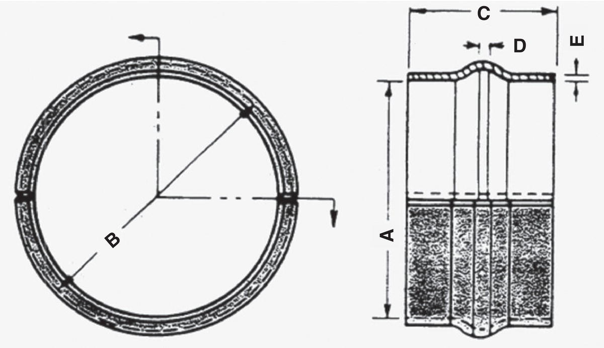
42.3.1 Type A Sleeves (Reinforcing)
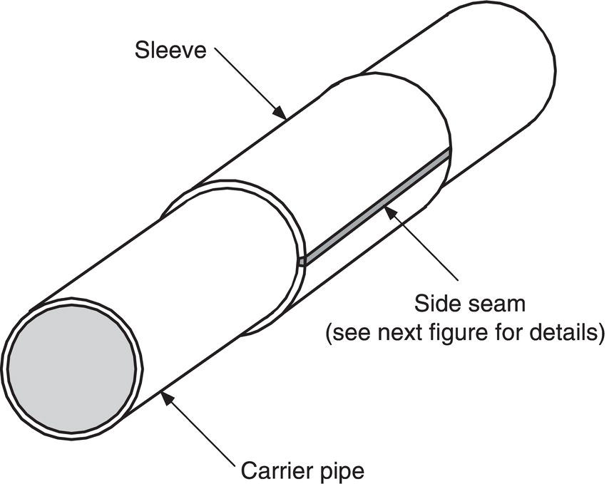
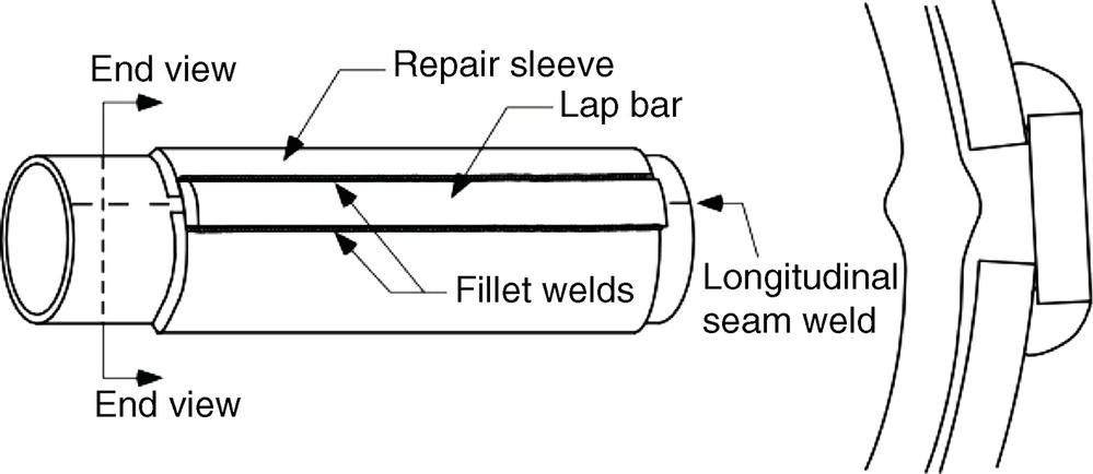
 , where D is the pipe diameter, t is the pipe wall thickness, and all dimensions are in consistent units. This is the length beyond which hoop stress can no longer distribute itself around the defect. For such defects, the role of the sleeve is limited to restraining bulging of the defective area. Bulging of the defective area occurs locally until the carrier pipe (or hardenable filler material) meets the inside diameter of the repair sleeve. As a result, they can be fabricated simply and, due to the fact that these sleeves function without necessarily being a high-integrity structural member, require no rigorous nondestructive inspection to ensure their effectiveness. Also, because Type A sleeves do not carry much hoop stress in the case of short defects, they can fulfill their restraining role without necessarily being as thick as the carrier pipe. As a rule of thumb, the thickness of a Type A sleeve should not be less than two-thirds of the thickness of the carrier pipe when used to repair short defects (according to the equation above), assuming that the sleeve is at least as strong as the carrier pipe. When designing a Type A sleeve, it is common to simply match the grade and wall thickness of the carrier pipe.
 , the sleeve thickness should be at least as great as that of the carrier pipe, again assuming that the sleeve is at least as strong as the carrier pipe. Alternately, a thinner, higher strength material may be used for the sleeve if it has the same pressure carrying capacity of the carrier pipe. Since hoop stress cannot redistribute itself around these longer areas, they may plastically yield, transferring some of the hoop stress to the sleeve.
42.3.1.1 Assuring Effective Reinforcement
Pressure Reduction
 ) should be capable of sustaining a significant amount of hoop stress and are expected to absorb an increased amount of hoop stress compared to sleeves used to repair short defects. The reason is that a long defect-weakened region will not be able to distribute hoop stress to the areas of the carrier pipe beyond the ends of the defect. Instead, the region will tend to yield plastically and transfer circumferential stress to the sleeve.
Mechanical Loading
Hardenable Fillers
Fit-Up on Submerged-Arc-Welded and Flash-Welded Line Pipe

42.3.1.2 Special Type A Sleeve Configurations
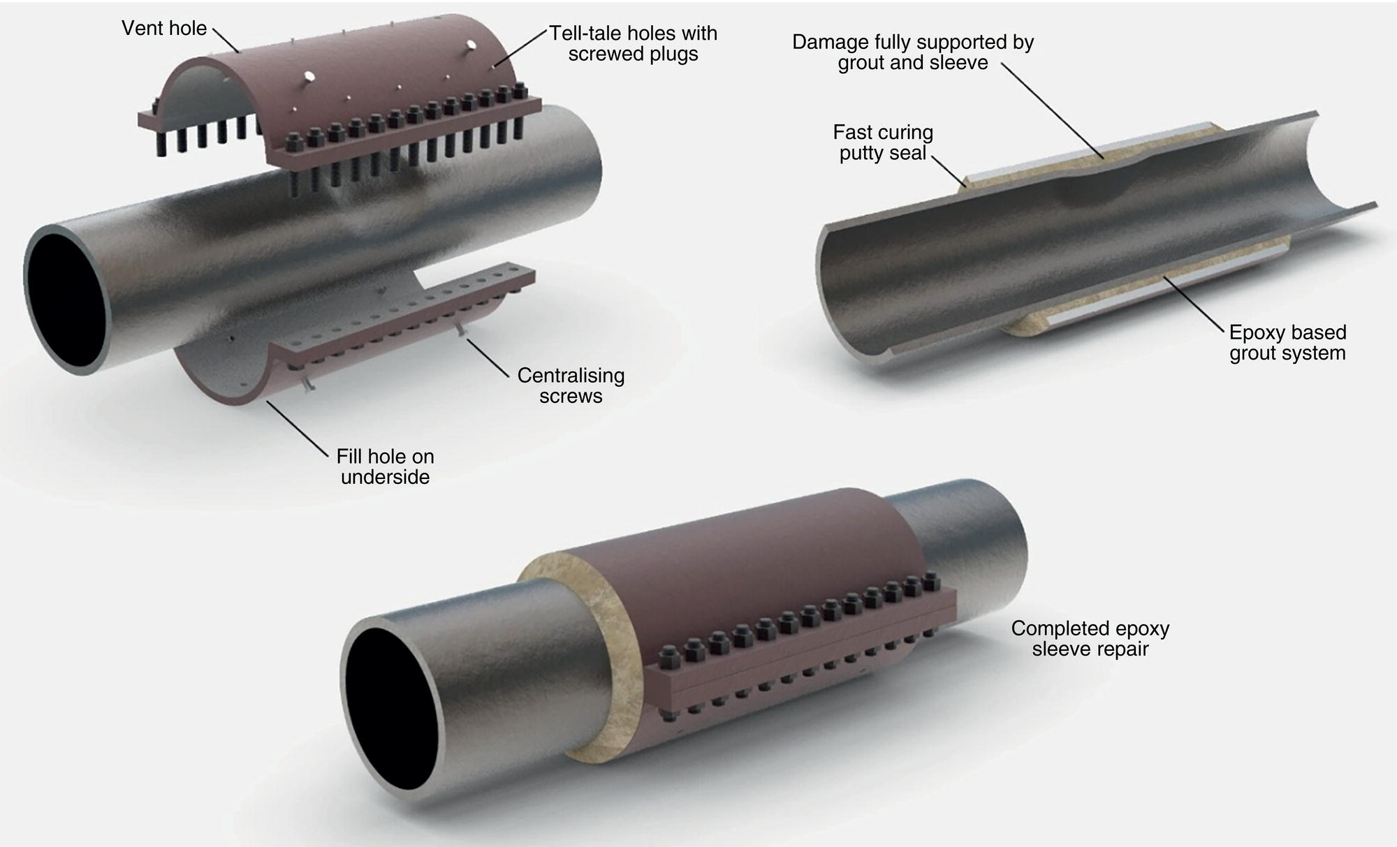
Epoxy Repair Sleeve
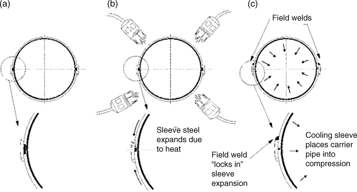
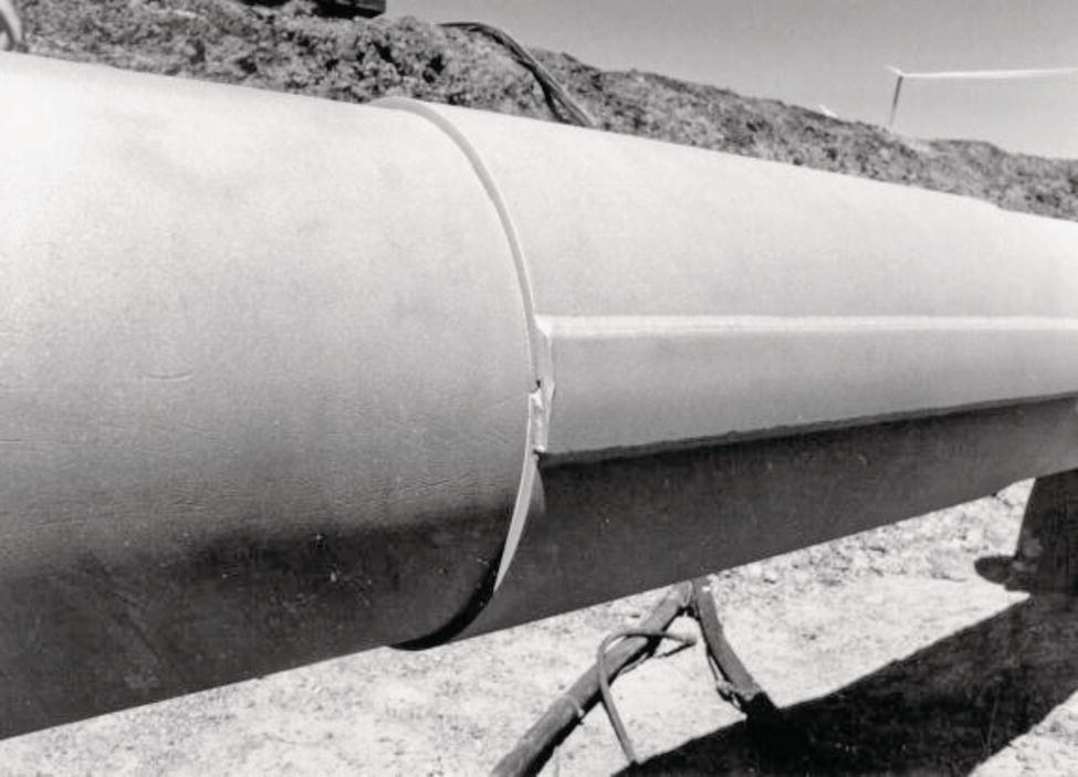
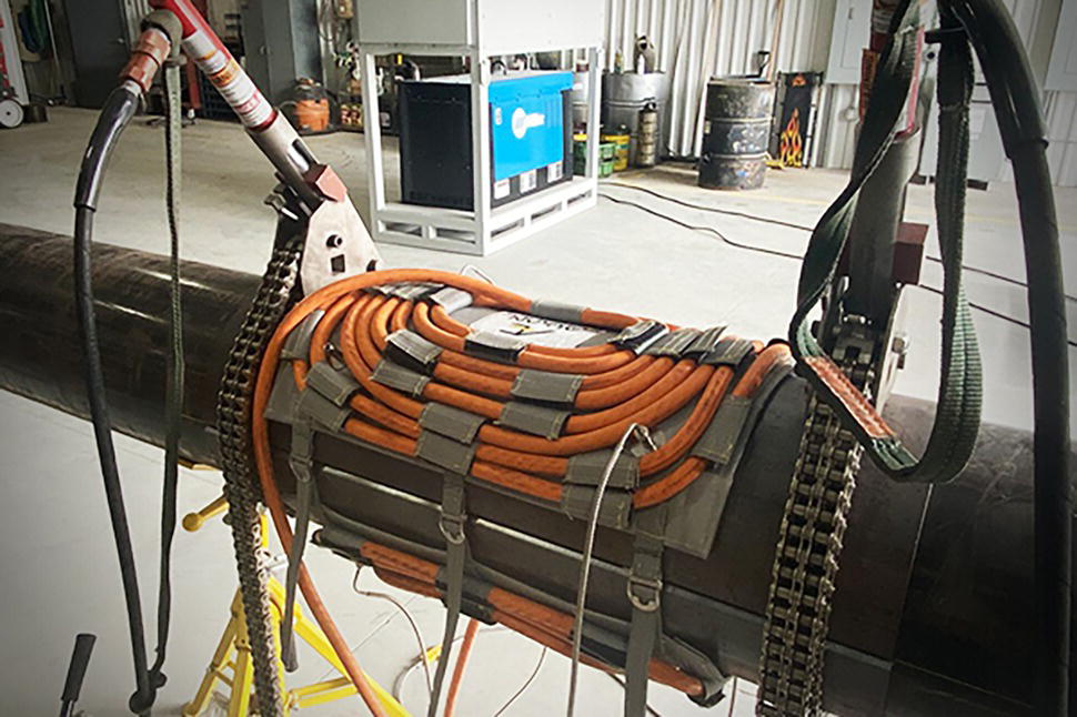
Steel Compression Sleeves
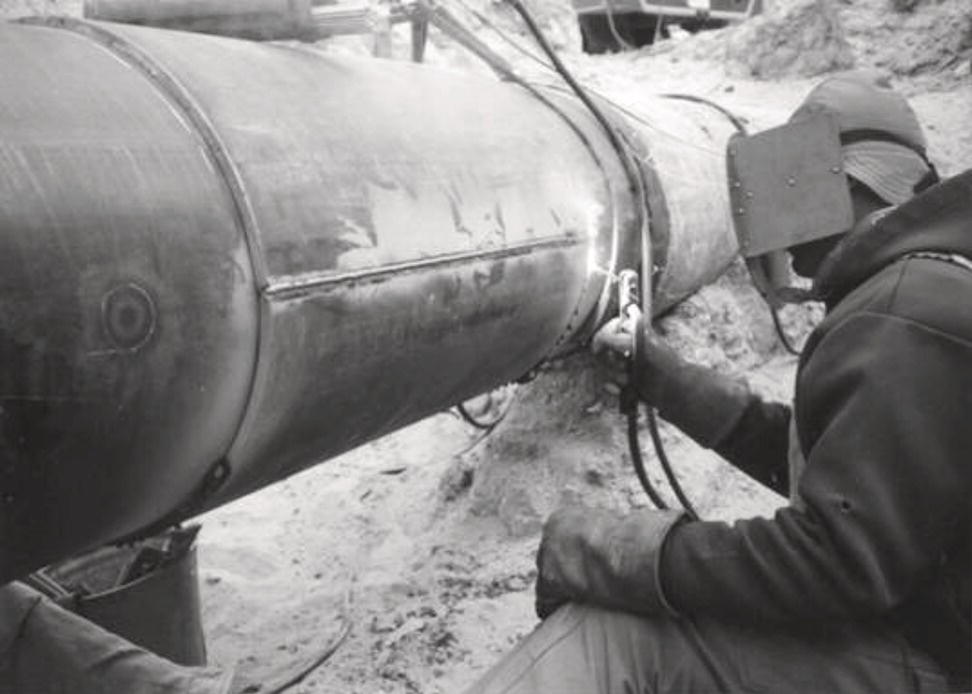
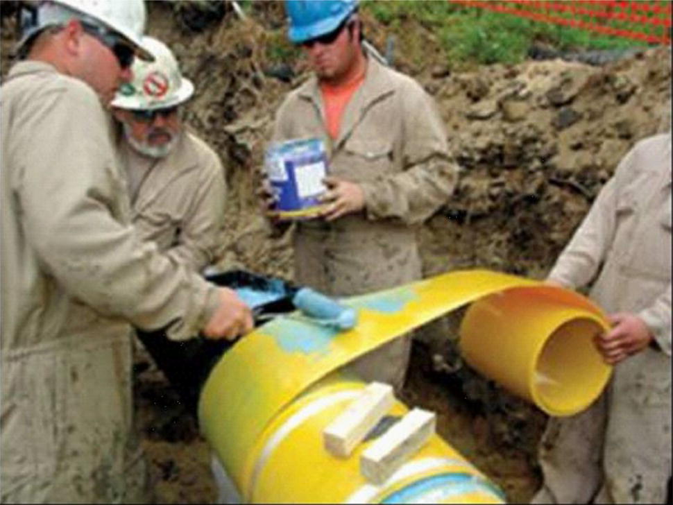
42.3.2 Type B Sleeves (Pressure Containing)
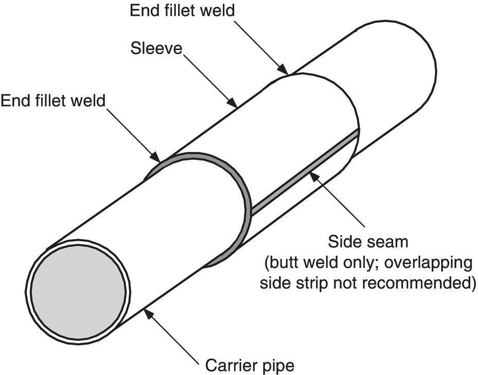
42.3.2.1 Design
The Importance of Quality Fabrication
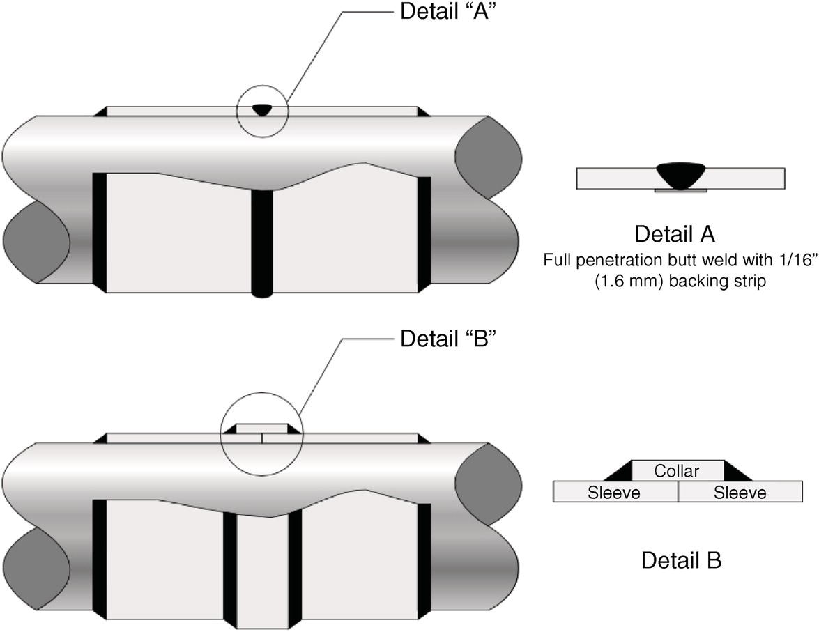
Sleeve Length
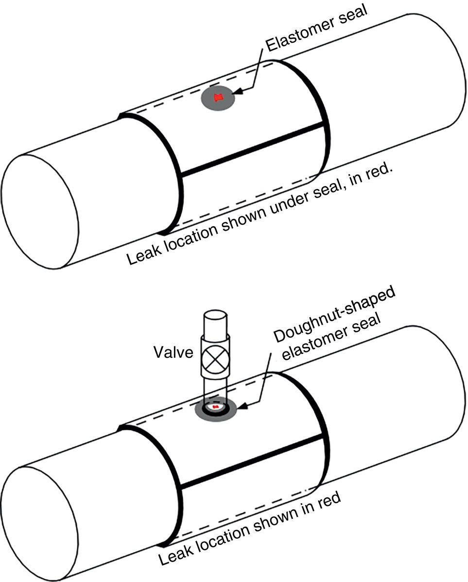
Leaking Defects
Nonleaking Defects
42.3.2.2 Special Type B Sleeve Configurations
Sleeves to Repair Girth Welds
Sleeves to Repair Couplings
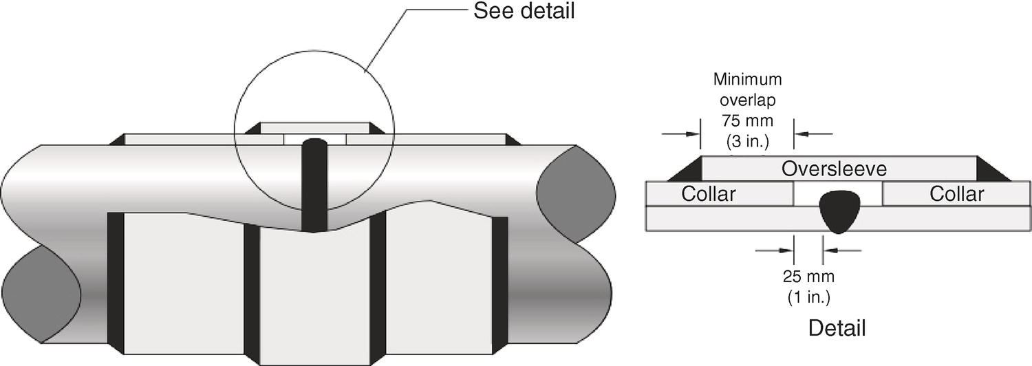
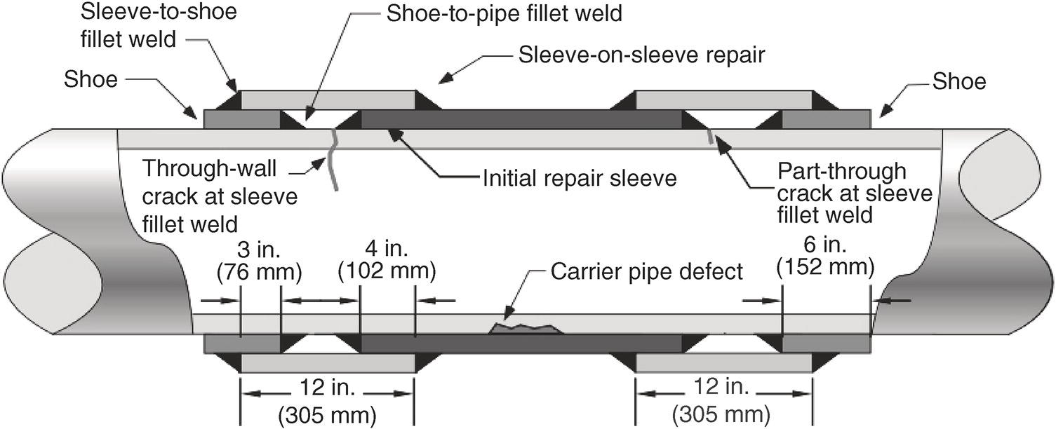
Sleeve-On-Sleeve Repair

Sleeve Configurations for Curved (Field-Bent) Pipe
Encapsulation or Leak Box Repair
42.3.3 Installation and Inspection of Full-Encirclement Sleeves
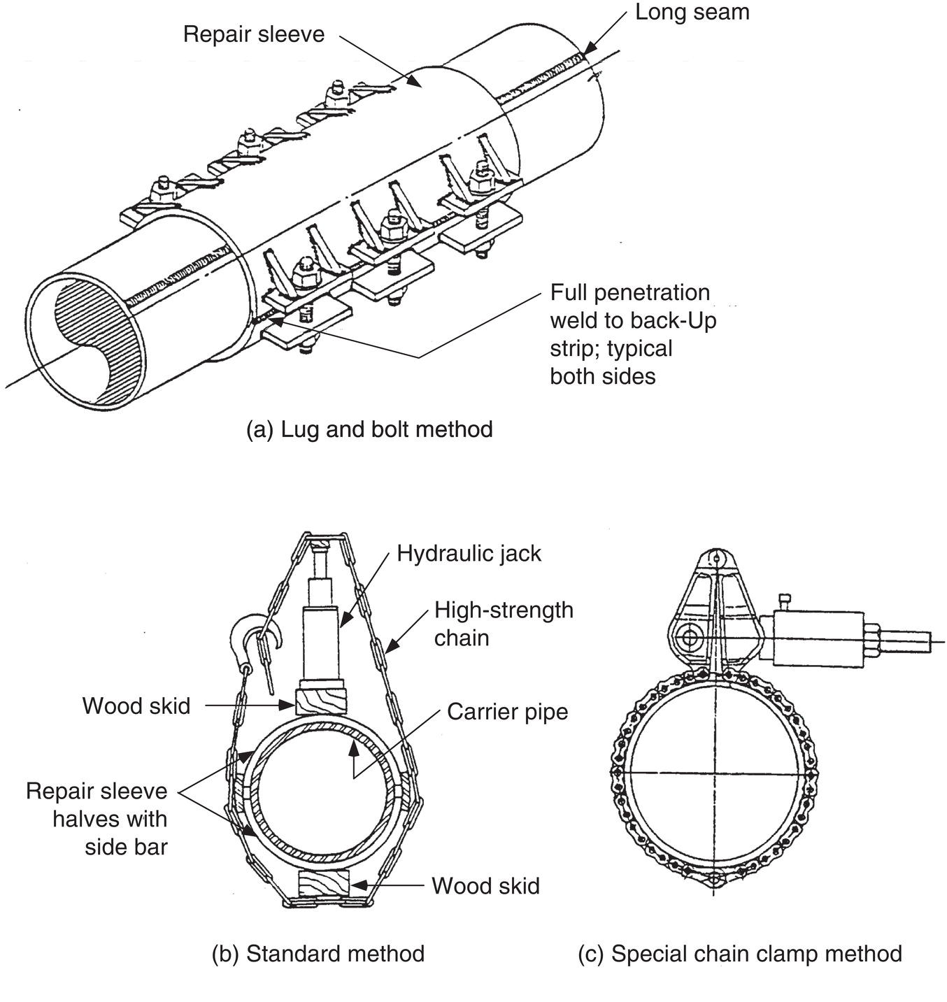
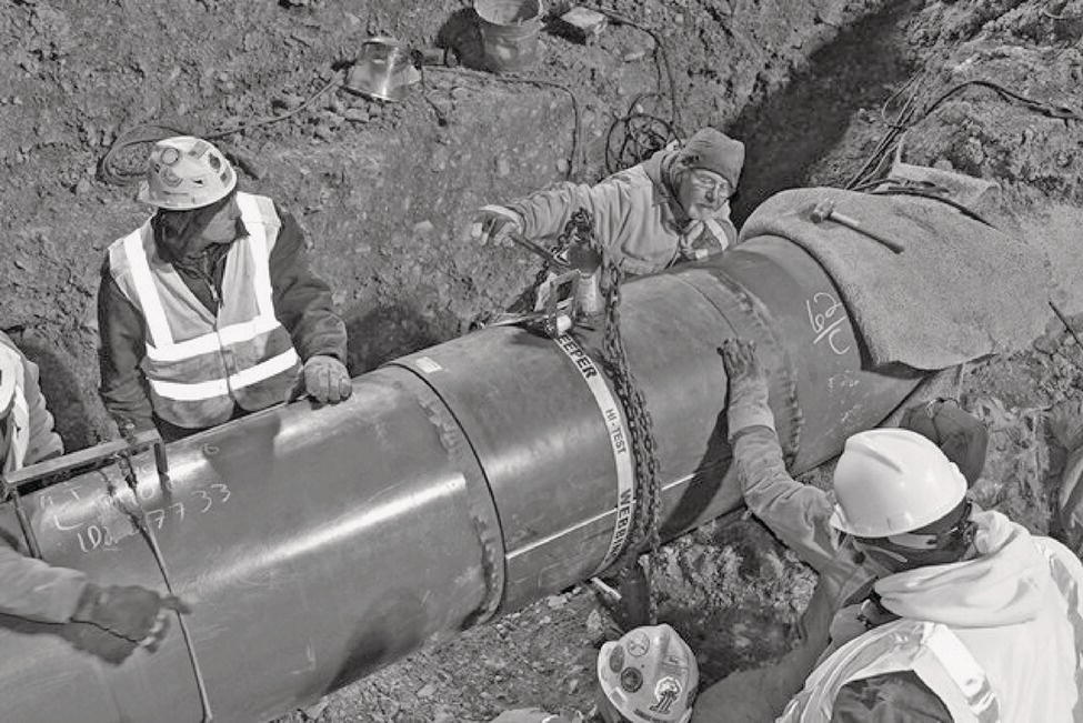
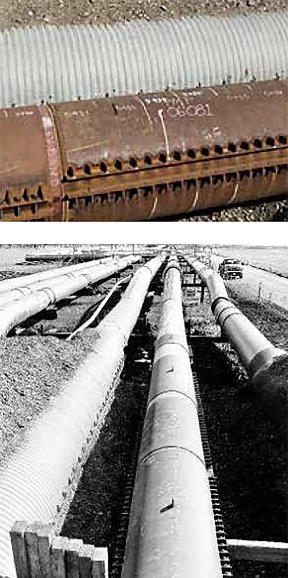
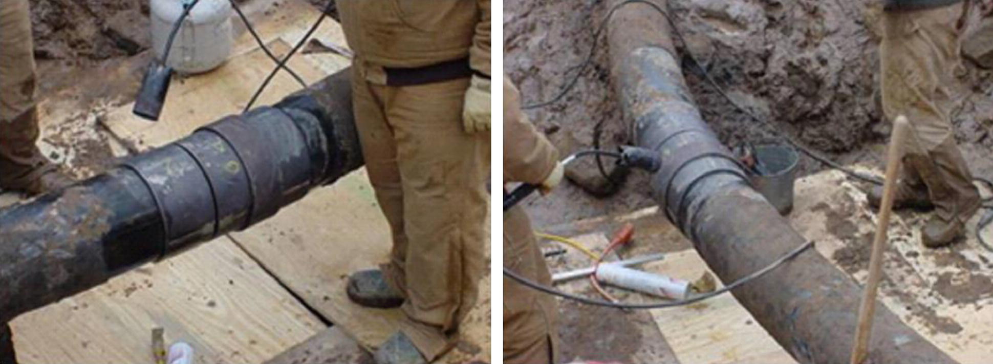
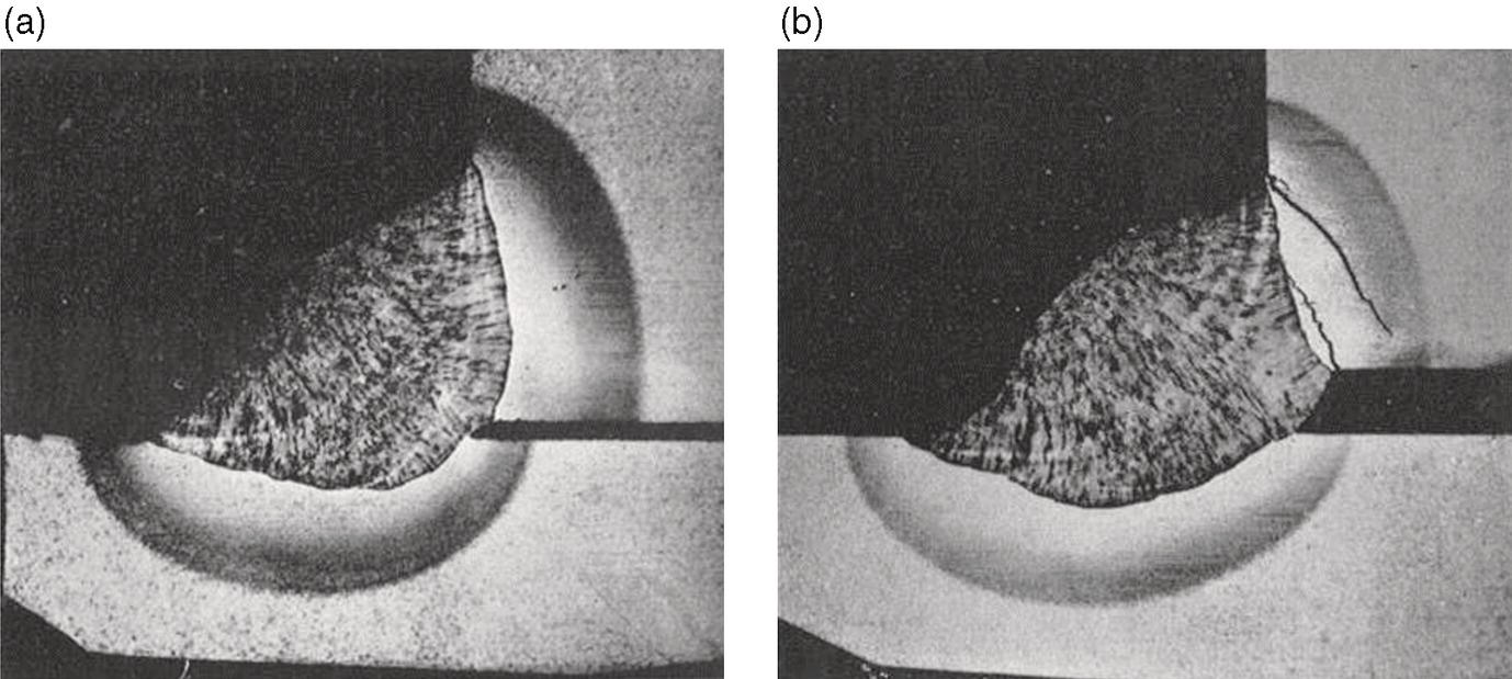
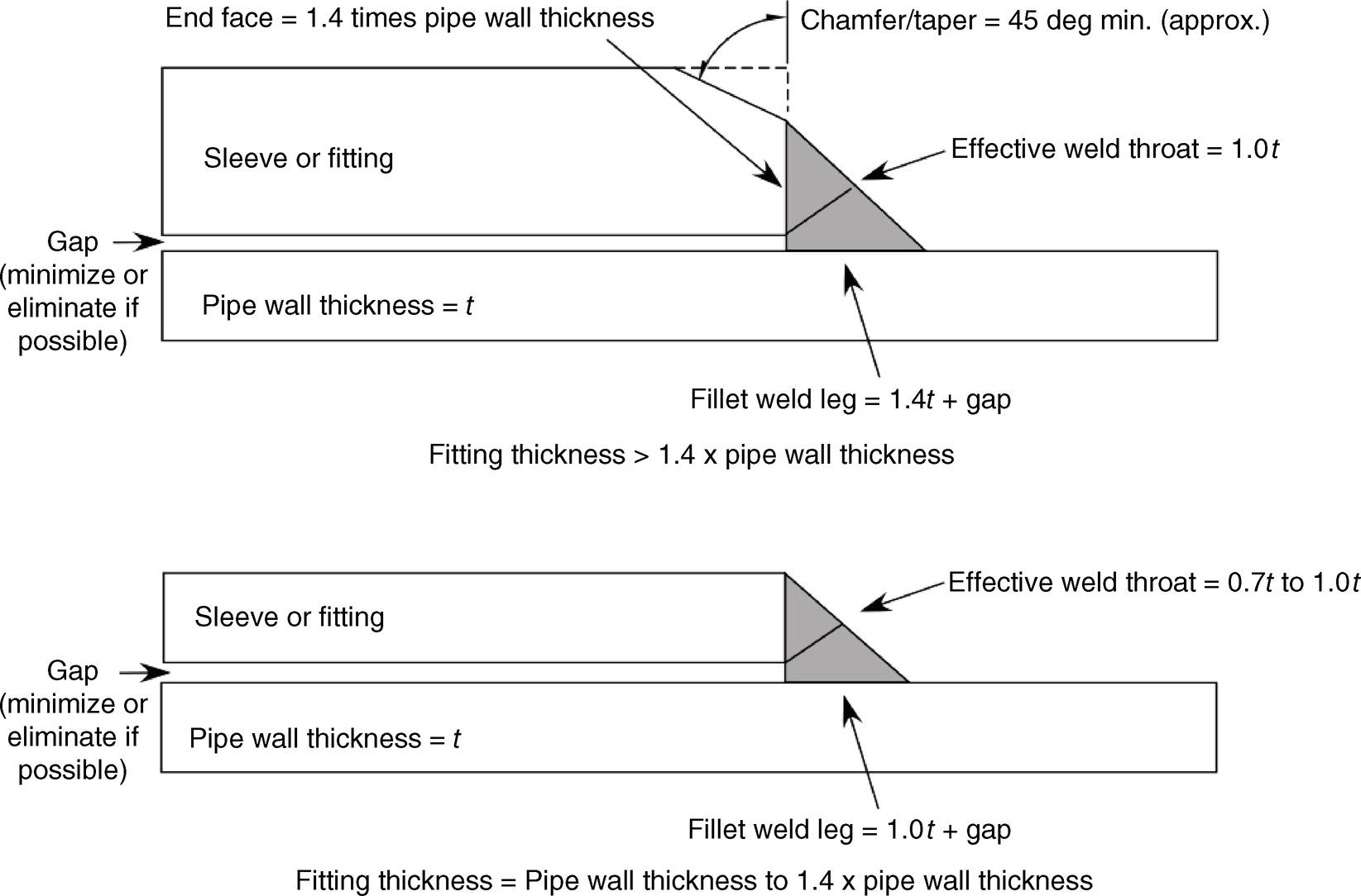
42.3.3.1 Installation
42.3.3.2 Inspection Requirements
42.3.4 Defect Repair Using Composite Materials
42.4 Comparison of Steel Sleeves and Fiber Reinforced Composite Repairs
42.4.1 Applicability to Various Defect Types
Type of Defect
Type A Sleevesa
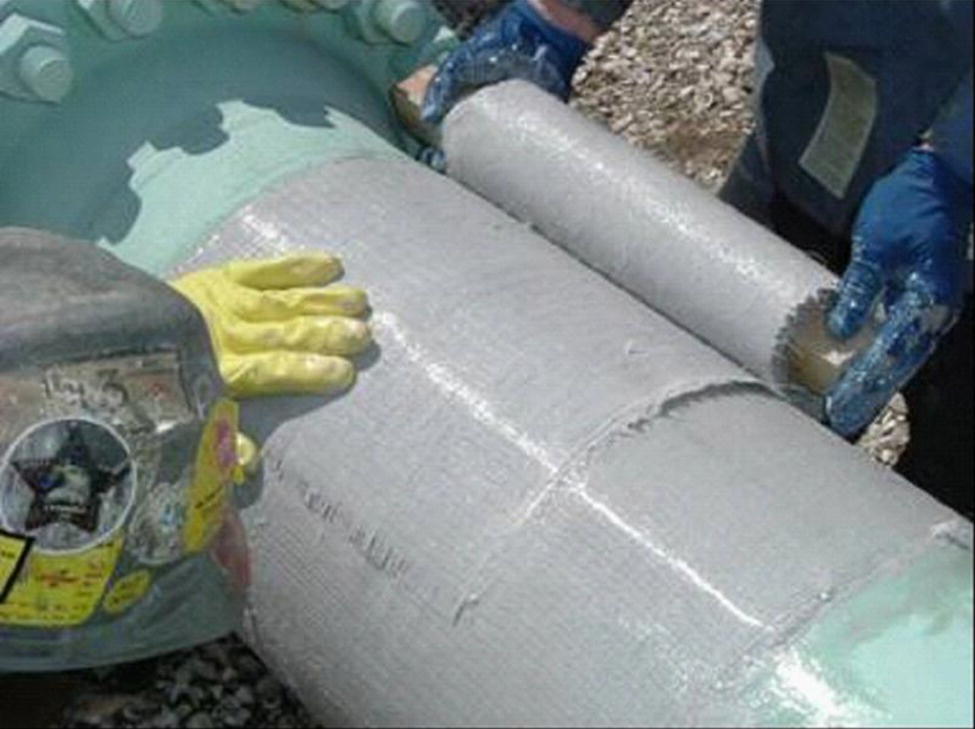
Composite Wet Wraps
Composite Rigid Coils
Type B Sleevesb
Repair Options for Various Types of Defects
1. Leak (from any cause)
No
No
No
Yes
2. External corrosion
2a. Shallow to moderate pitting <0.8t
Yesc
Yesc
Yesc
Yes
2b. Deep pitting ≥0.8t
No
No
No
Yes
2c. Selective seam attack
Limitedd
No
No
Yes
3. Internal defect or corrosion
Yese
Yese
Yese
Yes
4. Gouge, arc burn, or other metal loss on pipe body
Yesf
Yesg
Yesg
Yesf
5. Inclusion, laminations, or blisters
Yes
Yes
Yes
Yes
6. Hard spot (without cracking)
Yes
Limitedh
No
Yes
7. Dent
7a. Plain (smooth) dent
Yesi
Yesi,j
Yesi,j
Yes
7b. Dent with stress concentrator (gouge or groove)
Yesg,i,j
Yesg,i,j
Yesg,i,j
Yes
7c. Dent with corrosion
Yesi,j
Yesi,j
Yesi,j
Yes
7d. Multiple dents (k)
Yesi
Yesi,j
Yesi,j
7e. Dent in girth or seam weld
Limitedl, i
Yesi, j
No
Yes
8. Crack or cracking
8a. Shallow cracking <0.4t
Yesg, m
Yesg
Yesg
Yes
8b. Deep crack ≥0.4t
Limitedd
No
No
Yes
9. Seam weld defect
9a. Volumetric defect
Yes
Yes
Yes
Yes
9b. Linear defect
Yesg, m
Yesg
Yesg
Yes
9c. Defect in or near an ERW seam
Limitedd
Limitedh
No
Yes
10. Girth weld defect
Limitedl
Limitedh
No
Yes
11. Wrinkle bend or buckle
Limitedl
Limitedh
No
Yesn
12. Coupling or Defective Prior Sleeve Repair
No
No
No
Yesn
13. HIC
Yes
No
No
Yes
42.4.2 Advantages and Disadvantages
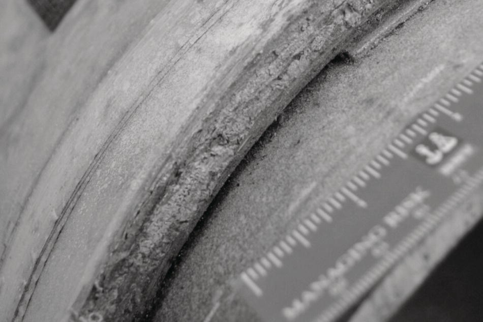
42.5 Welding Onto an In-Service Pipeline
42.5.1 Primary Concerns
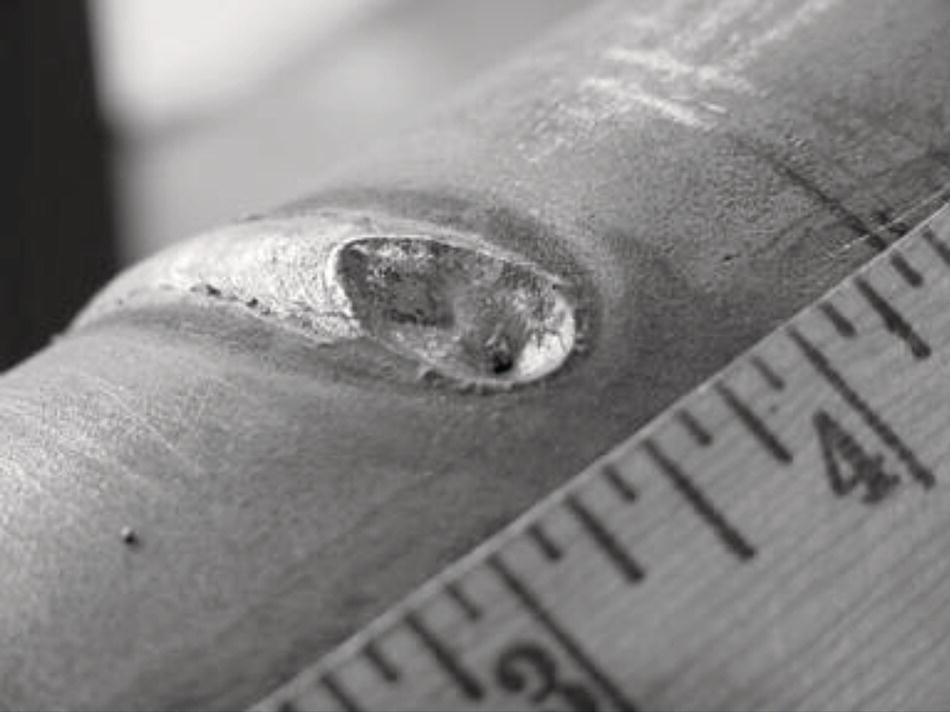
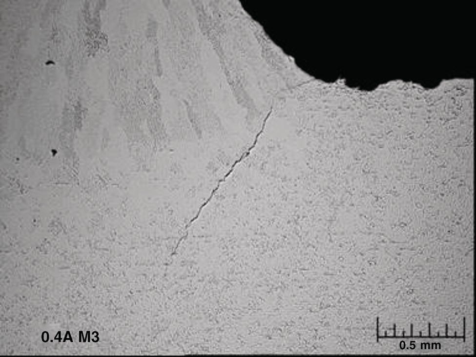
42.5.2 Preventing Burnthrough
42.5.3 Preventing Hydrogen Cracking
42.5.3.1 Control of Weld Hydrogen Levels
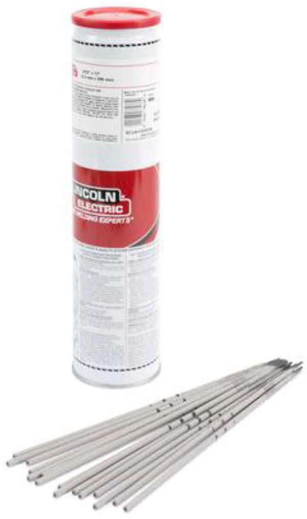
42.5.3.2 Development and Qualification of Procedures
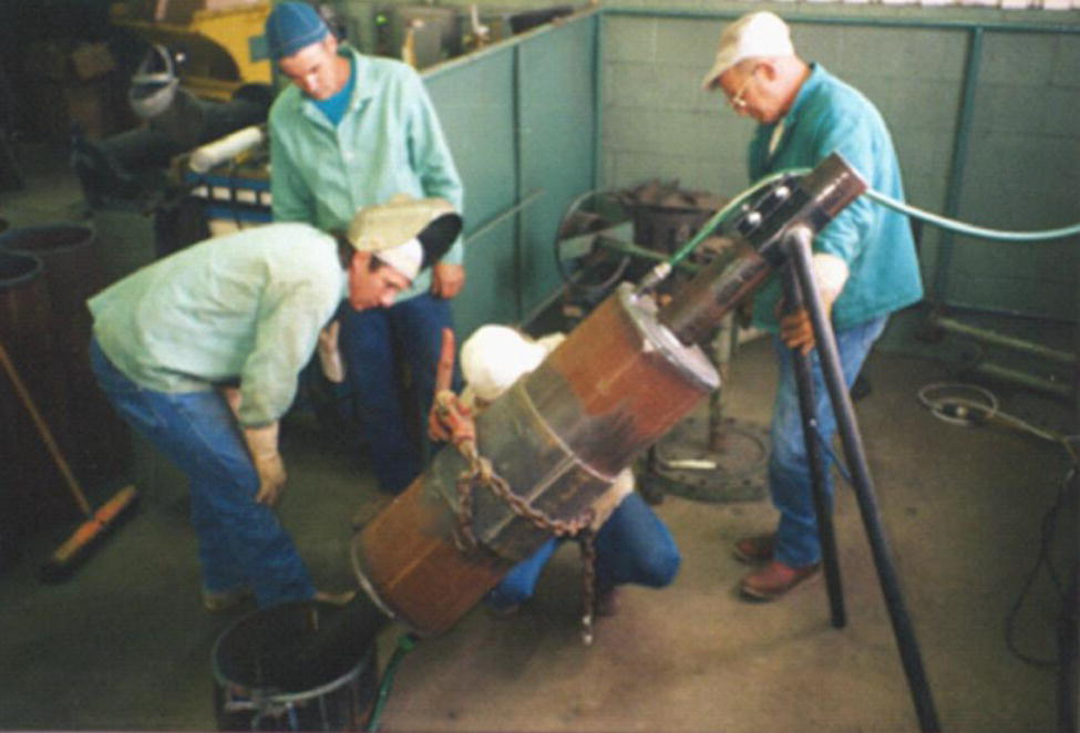
42.6 Summary and Conclusions
References
Notes