David Dorling1 and James Gianetto2 1Retired, Calgary, Alberta, Canada 2CanmetMATERIALS, Natural Resources Canada, Hamilton, Ontario, Canada A pipeline transportation system will most likely consist of gathering lines, a transmission system, and a distribution system. The gathering and distribution pipelines will be of a smaller diameter and will operate at lower pressures than the transmission line or lines. The smaller diameter pipelines (<406 mm diameter) are, in general, welded with conventional welding processes, such as manual shielded metal arc welding (SMAW). Design and operating stresses are relatively low, and there should be little difficulty in meeting the strength and toughness requirements. The welding of these pipelines is, in most cases, adequately addressed in national pipeline standards. For larger diameter transmission systems, material properties and subsequent weld metal and heat-affected zone (HAZ) property requirements may vary significantly. Economic considerations have resulted in the grade of pipe for long-distance pipeline construction increasing from X52 to X80 in common use today. Although both X100 and X120 pipe grades have been developed, their implementation is limited. Instead, the application of heavy-gauge X70 and X80 steel pipes has increased. In both cases, this was facilitated by advances in steelmaking and casting and the concurrent development of thermomechanical controlled processing (TMCP) of microalloyed steels. For larger diameter pipelines, SMAW with cellulosic electrodes has also proven to be very effective and, as the pipeline industry has traditionally been an extremely conservative one and despite the fact that cross-country pipeline construction essentially involves the repetition, from 40 to 80 times/km, of the same joint, manual SMAW is still widely applied. The use of mechanized gas metal arc welding with narrow weld bevels considerably reduces the volume of welding required, and the productivity is considerably higher than that achievable with cellulosic SMAW electrodes. Since the early 1970s, mechanized, short-circuiting gas metal arc welding (GMAW-S) and, more recently, pulsed gas metal arc welding (GMAW-P) have been applied to large-diameter construction projects, both cross-country and, more particularly, offshore. The limitations of manual SMAW are strongly evident under the restrictive circumstances of lay barge operation. For traditional stress-based designs, minimum quality levels with respect to welding are incorporated into pipeline construction by way of regulatory requirements, codes, standards, and company specifications. Some pipeline systems, for example, onshore pipeline systems in areas of seismic activity or discontinuous permafrost and offshore pipelines laid by the reel-lay method, may be expected to experience higher longitudinal strains than the vast majority of existing pipelines, and this has implications with respect to the development, qualification, and application of the pipeline welding procedures. Leaks and ruptures caused by defects introduced by welding are among the few pipeline incidents by far. Axial or longitudinal stresses from pressure loading are significantly lower in a completed pipeline than those in the circumferential or hoop direction. Discontinuities oriented in the axial direction, such as corrosion defects and stress corrosion cracks, have been a much bigger concern for pipeline owners and operators as potential failure of these axial-oriented discontinuities is driven by hoop stress. Pipeline incidents that do occur as a result of welding almost invariably arise not from a lack of knowledge but from failure to apply that knowledge. The construction of a long-distance, cross-country pipeline is carried out by specialized crews, generally using purpose-built equipment in a series of efficiently sequenced operations moving along the pipeline [1]. This is the “spread” method of pipeline construction that utilizes the principles of a production-line system, but, in the case of a pipeline, the product is static, and the workforce moves along the pipeline right of way. Welding (Figure 21.1) is only one of the many operations and must be undertaken in such a way as to maintain pace with and not impact the preceding and subsequent operations and crews. The sequence of events on the main welding line or firing line of a submarine pipeline pipe-lay vessel is practically identical to onshore pipeline construction. The main difference is that instead of each welding workstation moving along the pipeline, the joint being welded moves to successive welding stations as the vessel moves forward in steps corresponding to the length of the prefabricated pipe joint or pipe string [2]. A variety of conventional welding methods can and are being used for double jointing, mainline, tie-in, and repair welding (Figure 21.2). A number of less conventional methods are being actively pursued. The characteristics of the traditional welding processes, and some of the more innovative joining processes, are described by Dorling and Rothwell [3] and Jones and Hone [4]. Figure 21.1 Mechanized pipeline welding spread with a series of white protective shelters used during completion of root/hot, fill, and cap passes for each girth weld. (Courtesy of RMS Welding Systems.) Figure 21.2 Typical joint designs superimposed on macrographs of pipe girth welds (a) double joint SAW, (b) narrow gap mechanized GMAW-P, and (c) single-vee manual SMAW. The double-jointing process is the practice of welding two pipes together to form, for example, a single 24 m section from two 12 m pipe lengths. Double-joint welding is carried out prior to transporting to and stringing the pipe on the pipeline right of way. The advantage of double jointing is that half as many mainline welds are now required on the pipeline right of way. Double jointing is carried out at the pipe mill by the pipe manufacturer or at a pipe stockpile site by either the pipeline contractor or a double-jointing contractor (Figure 21.3). For submarine pipeline construction, double jointing of the pipe is carried out on board the pipe-lay vessel in very much the same way as it is done onshore [2]. As it is possible to rotate the double joint, a common practice is to use submerged arc welding (SAW), which has the advantage of high weld metal deposition rates with consistent weld bead profiles and properties for pipe materials to X80 for stress-based designs. SAW produces no spatter or visible arc and a relatively small amount of fumes. The process is very stable at high currents. The simplest form of the SAW process uses a single wire and a direct current power source; however, multitorch and multiwire systems are available [5]. Although not ideal from a productivity standpoint, double-joint welds can be completed using processes and procedures similar or identical to those qualified for mainline welding. They can be used in the 5G (fixed) position, as in an offshore pipeline spool base, or adapted for 1G (roll welding) as the pipe can be rotated. As with SAW, industrial multi-torch and multi-wire gas metal arc welding (or flux-cored arc welding) equipment are available if higher productivity is required. This also serves as a viable option to achieve more demanding high-strength weld metal requirements for strain-based design (SBD) applications [6]. For onshore pipeline construction, mainline welding refers to the welding of the pipeline in continuous lengths or sections between features such as roads, railway tracks, rivers, and other obstacles that may prevent the pipeline from being continuously installed in the trench. Completing this operation in a cost-effective manner relies on continuous advancement and optimum utilization of the welding crew, and any delays to this continuous process have to be minimized. Some joints will have to be left because they cannot be physically made at the time, others because the making of particular nonstandard welds, such as those required for heavy-wall pipe required at a crossing, will cause a disproportionate delay to the mainline production. Figure 21.3 On-site double jointing of large diameter pipes. The inset photograph shows a single torch SAW process (white arrow) used to deposit outside diameter weld pass. (Courtesy of RMS Welding Systems.) Once completed, the welds are inspected and coated, and the continuous lengths or sections of the pipeline are lowered into the ditch using several side-boom tractors working together. Two aspects of the mainline welding method determine the economics of pipeline construction: Although the fill passes do not control the progress of pipeline construction, the efficiency of fill and cap processes determines the overall joint completion rates and the number of fill stations and pairs of welders required. They take on increasing significance as the pipe wall thickness and diameter increase. An additional factor to consider in the case of submarine pipeline construction is that the number of welding workstations on a lay barge is limited by the space available. By the correct choice of consumables and welding technique, the SMAW process (Figure 21.4) can be used in all welding positions and will allow a wide range of property requirements to be met. It is thus an extremely versatile process; however, it is very dependent on the welder’s manual skills for the attainment of defect-free welds having acceptable properties, and its productivity is inherently limited by its intermittent nature. SMAW with cellulosic stick electrodes is still widely used today for general pipeline applications, including mainline welding. Welds made using cellulosic electrodes can also be susceptible to hydrogen-assisted cracking (HAC), as will be discussed later. Self-shielded, flux-cored arc welding (FCAW-S) wires are available for most pipe steels in common use today [7, 8]. The products are specifically designed for pipeline welding with a vertical-down progression. They require no external gas shielding and, therefore, are ideally suited to manual welding on the pipeline right of way. Higher weld metal deposition rates can be achieved, together with a higher duty cycle, by virtue of the continuous nature of the consumable, which results in a reduction in total welding time when compared with SMAW. Although attempts have been made to produce a wire for root bead welding, FCAW-S is primarily used for fill and cap passes, and productivity in terms of welds per day, at best, remains unchanged. Figure 21.4 Welders use manual vertical-down SMAW to complete pipeline girth weld. (Courtesy of RMS Welding Systems.) The continuous nature of the gas metal arc welding process and the virtual absence of slag covering on the completed weld led to high productivity and a process ideally suited to mechanization and automation [9]. It is also inherently low hydrogen in nature. First used in 1969, the mechanized gas metal arc welding process has become the standard for major, large-diameter, cross-country pipelines in Canada and is increasingly being used worldwide. Mechanized gas metal arc welding systems for mainline welding use lightweight tractors or “bugs” running on a band to align and carry the welding torches from the top to the bottom of the pipe. Small-diameter wires are used at a relatively high current (to give high metal deposition rates) with carbon dioxide or argon–carbon dioxide shielding gas mixtures. Welding progression is vertical down in a reduced-gap, compound bevel that is accurately machined on the pipe ends immediately ahead of the welding crew. The root bead is either completed with welding heads incorporated into the internal line-up clamp to produce a root bead from the inside of the pipe (Figure 21.5) or all passes are completed externally, with the root bead being run onto a copper backing bar, which is incorporated into the internal line-up clamp. Shelters or “shacks” provide protection from the elements. Figure 21.5 Front-end stabbing crew member monitoring pipe preheat temperature (left, arrowed) prior to positioning pipe section over internal welding system to facilitate root pass welding. Close-up of alignment clamp and multiple torch system (right, arrowed). (Courtesy of RMS Welding Systems.) For mainline welding, mechanized gas metal arc welding increases the number of welds that can be achieved in production on a daily basis and significantly reduces the welding crew size required to complete these welds. It has been demonstrated to be capable of upward of 140 defect-free welds per day under ideal conditions. Conventional, single-wire, mechanized GMAW-S was, up until recently, the most widely used mechanized process. However, the technology has now progressed to fully automated, higher productivity, multitorch, or multiwire GMAW-P (Figure 21.6) [10]. Most mechanized pipeline welding equipment suppliers have dual-torch welding systems that incorporate remote wire feeding and a pendant control, as well as the facility for through-arc sensing to guide the welding torch in the weld bevel. Multiwire or tandem GMAW-P systems (Figure 21.7), which differ from conventional GMAW-S or GMAW-P as two welding wires are passed through the same welding torch, have been used in some construction projects [11–13]. Figure 21.6 (a) Single-torch and (b) dual-torch mechanized pipeline welding. (Courtesy of RMS Welding Systems.) Figure 21.7 Tandem GMAW-P torch with two wires fed through isolated contact tips. (Courtesy of RMS Welding Systems.) Efforts continue to be made to develop alternative methods of welding pipelines of all size ranges [14–17], with the aim of not only improving economics and efficiency but also of providing weldment properties that are engineered for specific project requirements and reproducibly maintained in the field. The growing trend toward higher-strength pipe steels, a fitness-for-purpose approach to weld flaw acceptance, and the application of strain-based pipeline designs place increasing importance on the second of these factors. Lay-barge construction is most frequently used for submarine pipelines. The most common installation methods are S-lay, J-lay, and reeling. The methods, their history, and their application are described in some detail by Jensen [18]. With S-lay installation, the pipe is welded in the horizontal position, and the completed pipeline is laid onto the seabed over the stinger at the stern of the vessel. The stinger controls the curvature of the pipe from the horizontal to the inclined section. The pipeline takes an S shape from the vessel to the seabed. The welding of an offshore pipeline is, in many respects, not that much different from that of a cross-country pipeline. The root-pass welding speed governs the overall pace of construction. The wall thickness of an offshore pipeline is significantly greater than most onshore pipelines, and the number of workstations for filling and capping must be adjusted within the confines of the space available to maintain pace with the root bead welding. Nevertheless, the same welding processes can be used on a lay barge as on a pipeline right of way. In the J-lay method, the onshore prefabricated pipe lengths are welded on a vertical or near-vertical ramp and deployed almost vertically until it reaches the seabed, where it assumes the J shape. The J-lay method avoids some of the difficulties of S-lay, such as tensile load forward thrust, and can be used in deeper waters. Onshore prefabrication of the quadruple or hex joints used for J-lay installation can be made by mechanized, fixed-position GMAW-S or GMAW-P, or, as it is possible to rotate the joint, by SAW. On board, the J-lay vessel, automated, vertical position GMAW-S or GMAW-P circumferential welding takes place in one welding station using between two and four welding heads in a carousel. In the reeling method, the pipeline is installed from a large reel mounted on the pipe-lay vessel. Sections of the pipeline are welded at an onshore spool-base facility and spooled onto the reel. The vessel transports the pipeline to the installation site and deploys it to the seabed. Horizontal reels lay the pipe with an S-lay configuration; vertical reels most commonly deploy the pipeline in a J-lay configuration but can also deploy in an S-lay mode. On a cross-country pipeline construction project, a tie-in is any joint that connects two pipeline sections at road and river crossings and at points along the right of way where access has been required to both sides (work side and ditch side) of the pipeline. A tie-in also connects the pipeline to prefabricated assemblies or to existing pipeline systems. These tie-in welds and, often, the welds required to fabricate the short sections of pipelines to be inserted at these points are, as mentioned earlier, not completed by the mainline welding crew in order to maintain optimum utilization of front-end welding personnel and equipment and maximize daily weld production. Dedicated crews and equipment typically following some distance behind the mainline welding crew carry out tie-in and repair welds. Tie-in welds are normally performed with the pipe already in the trench (Figure 21.8). All operations are therefore carried out externally, and the accuracy of cutting, preparation, and alignment of the pipe ends prior to welding is critical. For tie-in and repair welding in all but the higher-strength pipe steels, the practice of using the SMAW process with cellulosic consumables throughout produces acceptable welds; nevertheless, as will be addressed in Section 21.5 of this chapter, the specification of welding procedures to avoid HAC must take into account all the relevant field variables. For higher-strength steels and heavier wall thicknesses, there is a greater susceptibility to HAC, and the use of cellulosic electrodes requires even more care. Low-hydrogen, vertical-down SMAW consumables are available; however, while adequate for filling and capping, they tend to behave poorly for root bead welding when the fit-up is less than ideal, and, consequently, productivity tends to be low. For up to X80 for stress-based designs, low-hydrogen, vertical-down SMAW is commonly used for hot, fill, and cap passes for both tie-in and repair with cellulosic SMAW for the root pass (i.e., a combination process) [19, 20]. Traditional low-hydrogen, vertical-up SMAW consumables are available specifically for root bead applications and are frequently used, although it can prove challenging to master the techniques required. Figure 21.8 Photograph showing pipeline crew setting up to complete a tie-in root pass weld with semiautomatic modified waveform GMAW. Pipe ends are properly aligned using an external line-up clamp (white arrow). (Courtesy of RMS Welding Systems.) For tie-in fill and cap passes, manual FCAW-S has been used for more than 20 years [20, 21]. Strength and toughness limitations have, in the past, restricted its application to X70 and below; however, consumables aimed at higher-strength steels and low-temperature toughness applications are now available. The importance of establishing robust FCAW-S welding procedures with appropriate techniques to ensure adequate girth weld toughness properties was addressed in recent work sponsored by Pipeline Research Council International (PRCI) [21]. The authors indicated that consistently achieving a refined weld metal structure through reheating of previously deposited weld passes was necessary to reduce the toughness variability of semiautomatic FCAW-S welds produced in X70 and X80 high-strength pipe materials. Manual, gas-shielded, flux-cored arc welding (FCAW-G), with rutile cored wires, is being increasingly utilized for fill-pass applications in short sections of pipeline, as well as tie-in and repair welding for large-diameter pipeline projects where significant productivity improvements over SMAW can be realized [19]. The mechanization of FCAW-G for fill and cap passes offers the potential for further improvements in productivity, and mechanized FCAW-G (Figure 21.9) has been used worldwide for a number of years for tie-in welding and the welding of short sections. The process is also seen to be increasingly used in mainline welding applications where flexibility of operation is more important than daily weld production [22, 23]. Most of the pipeline-welding equipment manufacturers provide external welding systems for FCAW-G, and all are very capable of mainline, short-section, and tie-in welding. Figure 21.9 Mechanized all-position FCAW-G field welding. (Courtesy of RMS Welding Systems.) Novel flux-cored arc welding wire formulations for the welding of higher-strength pipes are becoming available. These new formulations result in outstanding weld metal strength and toughness while appearing to depart from the typical mechanisms of microstructural development [24, 25]. Controlled short-circuiting GMAW-S is increasingly being used as an alternative root bead welding process, especially for higher-strength pipes. The Lincoln Electric Company Surface Tension Transfer (STTTM) [26], Miller Electric Regulated Metal Deposition (RMDTM), and Fronius Cold Metal Transfer (CMTTM) have been used for the deposition of full-penetration root beads in conjunction with manual and mechanized FCAW-G on a number of pipeline projects [22, 23, 27]. The STT, RMD, and CMT process options are considered to be advantageous for the welding of higher-strength steels because of their low-hydrogen potential and the ability to alter the deposited weld strength through selection of different welding wires and shielding gas compositions. On a submarine pipeline, the tie-in of pipeline segments and connection to surface facilities is completed by either welding or with mechanical connectors. The tie-in operations can be performed on board the pipe-lay vessel (in which case welding is preferred) or underwater. In the case of a tie-in welded underwater, hyperbaric welding is the more common method [2]. On the seabed, the pipeline segments lay parallel to each other and overlap. The ends of each segment are cut, and a welding plug is then inserted into each end of the pipeline segments. The plugs are inflated for a perfect seal. The pipe ends are then beveled with a beveling machine to prepare them for welding. Pipe handling frames lift the pipeline ends and align them to be ready for welding. The welding habitat is then lowered and positioned precisely over the two pipe ends. Compressed diving gas is used to push water out of the opening at the bottom of the habitat to make it a dry zone where the divers can work without diving equipment. The previously installed seals separate the water in the pipeline segments from the dry area of the welding habitat. Before welding begins, the beveled pipe ends are measured to ensure they meet specifications. Divers, who are qualified welders, complete the welding or, in some cases, the entire process can be controlled remotely from on board the dive support vessel, in which case the divers monitor this process from within the welding habitat. The completed weld is inspected using ultrasonic inspection. If the weld meets the requirements, the welding habitat is lifted back aboard the vessel. The pipe handling frames lower the pipeline back to the seafloor, and the rest of the equipment is retrieved. For pipeline sections that will be designed and built in accordance with standard industry practices (in conventional pipeline areas where pipeline designs are stress-based), the determination of girth welding inspection methods and weld flaw acceptance criteria is well-defined. Flaw acceptance criteria can be derived directly from the workmanship-based acceptance standards contained in the governing code or standard or alternative weld acceptance standards based on engineering critical assessment (ECA) can be developed in accordance with the procedures and requirements also included in pipeline codes and standards, for example, the American Petroleum Institute (API) standard API 1104 Appendix A, Canadian Standards Association (CSA) standard CSA Z662 Annex K, and Det Norske Veritas (DNV) Offshore Standard DNV-OS-F101 Appendix A. Alternative weld acceptance standards based on ECA allow engineers to assess the suitability of welds containing flaws for intended service conditions and can provide a more relaxed defect allowance than the workmanship criteria without sacrificing the integrity of the pipeline. Historically, film-based radiography has been used to inspect pipeline girth welds, and most workmanship-based flaw acceptance criteria are founded on the assumption that weld inspection is carried out using radiography. A source of radiation is placed on one side of the pipe, and the film is placed on the other side. X- and gamma-rays can pass through the metal, and a two-dimensional, gray-scale image is obtained of the transmitted radiant energy. X- or gamma-ray absorption depends strongly on the material density and volumetric defects, which have either a higher or lower density (such as porosity or most slag inclusions). The radiation that reaches the film in a potential flaw area is different from the amount that impinges on the adjacent areas. This produces on the film a latent image of the flaw that, when the film is developed, can be seen as an “indication” of different photographic density from that of the image of the surrounding material. Digital radiography is one of the newest forms of radiographic imaging. Digital radiographic images are captured using special phosphor screens containing microelectronic sensors. Captured images can be digitally enhanced for increased detail and are easily archived, as they are digital files. Real-time radiography is the latest application for inspecting pipelines, which lets electronic images be captured and viewed in real time, allowing cycle times of 4 min or less. Unfortunately, radiography only provides quantitative information about the flaw length and lateral position across the weld. It does not provide information about flaw height and, unless favorably orientated, tight, crack-like defects can be missed. In addition, many cosmetic imperfections are repaired in the absence of key height information. Ultrasonic-based inspection methods are well suited to find planar or crack-like flaws and techniques such as automated ultrasonic testing (AUT) are increasingly being used to inspect pipeline girth welds, especially those produced by mechanized welding systems using complex bevel geometries. AUT provides more information about the flaw, especially flaw height and wall position; these dimensions have a significantly greater effect on integrity than flaw length alone. AUT is currently employed for the inspection of both cross-country and submarine pipelines. Systems are usually configured to perform a fine-increment, zone-focus inspection. A time-of-flight diffraction (TOFD) arrangement may also be used in parallel. TransCanada (currently TC Energy) and RTD of the Netherlands developed the zone-focus approach in the mid-1980s following many years of field and laboratory experimentation [28]. This approach has been applied by TransCanada since 1989 and has been adopted worldwide for both onshore and offshore pipeline construction. The weld bevel is divided into discreet zones, typically 1–3 mm high. The number of zones is determined by the weld bevel configuration, wall thickness of the pipe, and welding procedure (Figure 21.10). The first AUT systems used arrays of transducers with individual transducers tailored for and dedicated to the portion of the bevel being interrogated and the type of defect expected. The sound field characteristics in terms of angle, focus, and focal size of beams generated by conventional transducers are fixed by the transducer itself (frequency, size, lens, and wedge) and cannot be changed without a physical change of the transducer. The weld is divided into two virtual halves—an upstream side and a downstream side. Up- and downstream sides are inspected with mirror-like sets of transducers. Figure 21.10 Zone discrimination concept as applied to a 19-mm-thick pipe mechanized girth weld. ([29]/Adapted from Moles et al. (2004).) Phased-array ultrasonic inspection systems have recently been introduced [29, 30] that can generate a range of ultrasound beams from the same transducer, controlled dynamically in real time by software. Instead of a single element, a phased-array system uses multiple elements in a common housing. Each element is connected to a separate pulser and time delay generator and is pulsed using a focal law. This focal law defines which elements are to be pulsed and with what time delay. By adjusting the time delays, normal beams, angled beams, focused or unfocused beams, and shear waves or longitudinal waves can be generated. For pipeline applications, a linear array of up to 128 elements in a single housing is used. The elements are pulsed in groups of 8–16. Pulsing a group of elements in sequence along the length of the transducer produces an electronic (linear) scan, which achieves the same objective as a raster scan. The beam is steered by delaying the pulsing of each element electronically at a set rate. Focusing is achieved by varying the rate of delay applied in sequence to the selected elements, while the actual size of the focus is determined by the number and size of the elements used. These electronic focusing and steering techniques, together with shaping the elements in the circumferential axis, result in a proper sound field being generated at the weld bevel. Phased arrays are also capable of sectorial scanning, which can improve sizing accuracy for poorly oriented flaws. Sectorial scanning sequentially sweeps the beam electronically through a range of inspection angles. TOFD has proven itself to be a particularly valuable tool for detecting HAC, especially during the inspection of shielded metal arc welds. TOFD is a time-based method relying on the diffraction of ultrasonic waves from the tips of discontinuities. This technique uses a pair of longitudinal wave transducers, in a transmit-receive configuration, that have a refracted angle between 45° and 70°. When the wave is incident on a linear discontinuity, such as a crack, diffraction takes place at the extremities of the flaw in addition to the normal reflected wave. This diffracted energy is emitted across a wide angular range. The TOFD method also uses transmitted and reflected waves as references to place all other signals in their correct position in the pipe wall, through-thickness direction. The first reference is a lateral wave traveling directly between the transducers just under the scanning surface, and the second reference is the reflection from the inside surface. An imperfection in the through-thickness direction produces signals that occur in the time interval between the reference signals, and the height of the imperfection is directly related to the time separation between these diffracted waves. The approach of using a combination of fine-increment, zone-focus inspection with sectorial scanning, and TOFD provides several different and separate assessments of any flaws present, significantly improving the probability of detection and confidence level achieved with respect to detection and sizing accuracy [13]. As the flaws can now be quantified based on their position within the weld and their vertical height and length, they can be readily assessed using an alternative weld acceptance standard based on ECA [31–33]. This avoids the unnecessary repair of those imperfections that do not pass workmanship-based acceptance criteria and, on any rational basis, will have no effect on the integrity of the pipeline. Work directed toward the treatment of weld discontinuities by ECA has been in progress for more than three decades [34]. An approach to brittle fracture based on the crack-tip opening displacement (CTOD) test was developed in the United Kingdom over several years and encapsulated in the then British Standards Institute (BSI) PD 6493 in 1980 (the revised PD 6493 is now published as British Standard Guide BS 7910). The evolution of BS 7910 is shown in Figure 21.11 [35]. This basic methodology was adapted in Canada for use on pipeline girth welds and combined with a check for plastic collapse failure. A rather extensive series of full-scale tests was undertaken on large-diameter girth welds containing known defects and this, together with analysis of some comparable data from the literature, allowed the effective flaw size curves from PD 6493 to be adjusted to give a more acceptable range of safety factors (ratio between observed and predicted failure strains). It also confirmed the conservatism of the plastic collapse approach. Many girth weld ECA procedures have their roots in the CTOD design curve approach and PD 6493. By the mid-1980s, BSI 4515 Appendix H, API 1104 Appendix A, and CSA Z662 Appendix K (later Annex K) were added to their respective main documents. Over the years, more accurate methods of assessment for pipeline girth welds have evolved with the incorporation of the failure assessment diagram [31–34]. Figure 21.11 Evolution of BS 7910. (Adapted from Ref. [35].) In carrying out an ECA, one of the key inputs is the height of the imperfection; if this is known, detailed calculations of tolerable flaw lengths can be made. Alternative weld acceptance standards, which are based on the engineering design aspects of the pipeline, can therefore make full use of the relationship between applied stresses or strain, material toughness, and flaw size when ultrasonic inspection is performed. If radiographic techniques are used, then assumptions on the height of the imperfection have to be made. Assuming that the height of the imperfection is limited to one weld pass may be appropriate for volumetric flaws but is questionable for planar flaws as they may extend for more than one weld pass. As planar flaws are most significant in terms of structural integrity, the use of radiography would lead to a very conservative alternative weld acceptance standard, together with the likelihood that significant defects might not be detected anyway. The design of the ultrasonic approach gives specific information about the height of the imperfection in any region and, therefore, a detailed analysis can be carried out to specify allowable imperfection lengths, which can be read directly from the charts produced by the ultrasonic unit’s data acquisition system. From an overall quality and process control perspective, another considerable benefit of AUT is its ability to stay directly behind the welding crew, where it can facilitate immediate identification, and hence rapid feedback and correction, of any recurring welding problems. Radiographic inspection is typically delayed because of radiation exposure concerns for nearby personnel. Qualified welding procedures are necessary to fulfill regulatory requirements and provide guidance to project engineers, pipeline contractors, and welders. The welding procedures, when incorporated in project-specific joining plans, provide essential guidance to the pipeline contactor with respect to welding crew setup and production targets. This will help maximize productivity with the appropriate combination of welding process, weld deposition, travel speed, and process efficiency (weld-to-weld time) while meeting defined weld quality requirements. For traditional stress-based designs, minimum quality levels are incorporated into pipeline construction by way of regulatory requirements, codes, standards, and company specifications. For example, in the United States, it is first necessary to comply with Title 49 of the Code of Federal Regulations (CFR), Part 192 (49 CFR Part 192), and in particular Subpart E “Welding of Steel Pipelines.” API standard API 1104 “Welding of Pipelines and Related Facilities” is incorporated by reference at 49 CFR §§ 192.7, 192.225, 192.227, and 192.229. In Canada, it is necessary to comply with the Canada Energy Regulator (CER) formerly the National Energy Board (NEB) “Onshore Pipeline Regulations” (OPR-99). CSA Standard CSA Z662 “Oil and gas pipeline systems” is incorporated in the CER regulations and provides a technical basis for OPR-99 by setting out the minimum technical requirements for the design, construction, operation, and abandonment of pipelines. Pipeline operating companies often develop their own general or project-specific welding requirements to be used in conjunction with regulatory requirements and national codes and standards. Documented, qualified welding procedures are a mandatory requirement of pipeline codes and standards such as CSA Z662, API 1104, and associated regulations. These standards require that the welding procedures be qualified prior to the commencement of welding operations and that welds be deposited only by welders trained and qualified in the welding operation defined by the qualified welding procedure. The welding procedure is the primary tool for controlling quality and achieving the design requirements in welded construction. As part of the quality assurance program, an overall welding procedure qualification protocol will need to encompass all of the combinations of pipe (grade, diameter, mill, etc.) and welding procedure (process, consumables, heat input, etc.), which will be encountered on the pipeline construction project. The codes and standards provide guidance and minimum requirements as to the number of and how the procedure qualification weld or welds are to be made, the inspection to be carried out, and the subsequent assessment of flaws. Also stipulated will be the types of mechanical tests to be carried out, the number and dimensions of mechanical test specimens required, their location in the weld, and the minimum values to be achieved. When working with typical code-established, workmanship-based flaw acceptance criteria, only tensile and bend testing may be required to qualify a procedure. API 1104 and CSA Z662 also include nick-break testing. More stringent industry codes, or the operating company itself, may include Charpy V-notch toughness testing and hardness testing of the weld cross-section. If ECA-based, alternative flaw acceptance criteria are specified, fracture toughness testing such as CTOD testing may be stipulated. Standard ECA applicability normally covers demands up to only 0.5% strain. A qualified welding procedure also provides the basis for producing welds with the required properties in an efficient manner without giving rise to defects. Company-specific welding procedure specifications (WPSs) may contain supplementary requirements that are applicable to the welding processes to be used and the project design requirements. Further assurance of quality is provided by the routine monitoring of welding parameters in the field and through visual and nondestructive inspections. For pipeline facilities and assembly construction, it may be permissible to qualify welding procedures in accordance with the requirements of the American Society of Mechanical Engineers (ASME) Boiler and Pressure Vessel Code. For example, ASME BPV Section IX is required in Canada, and ASME BPV Section IX and API 1104 are required in the United States. This applies to welds that are A WPS is mandatory and is the basis of the work instruction given to the welder. This work instruction may be in the form of a WPS data sheet. The WPS must reference the procedure qualification record(s) (PQR) on which it is based and provide sufficient information to produce the required weld in a controlled manner. It must include all the information to control any parameter that may adversely affect weld quality and the ranges of essential variables that the welder must work within to meet the qualification requirements of the applicable code or standard and any company- or project-specific supplementary specifications. Where a specific welding application requires the use of welding parameters outside of the range of these essential variables, the welding procedure must be requalified. A PQR is mandatory and is the critical record in the development and qualification of the welding procedure. It is used as the basis for the completion of the WPS and is a confirmation that the welding procedure to be used will comply with the requirements of the applicable code or standard and any company-specific supplementary specifications. A PQR may be used as the basis for more than one WPS. This document serves as a record of all measured welding parameters used in the production of the qualification test weld and the results of required nondestructive and destructive testing. Welder training and qualification is a code requirement and must be completed with the welding procedures that will be used on the project. Pipeline codes in North America (CSA Z662 and API 1104) only require the welder to complete one weld (or segment of a weld) to demonstrate their skill and if the weld meets the required testing, the welder is considered qualified. However, with the increasing sophistication of pipeline welding processes, the welder must be given the opportunity and time to become fully acquainted with how the equipment works and what limits he or she has control over. For mechanized welding, past experience has shown that a minimum of three, half-circumferential, training welds will need to be completed before presenting the welder for testing. HAC in welds was first recognized as a problem in the late 1930s and has been extensively studied since that time. Hydrogen cracking during fabrication of steel structures still occurs today but on a much-reduced level [36]. In fact, most of these continuing occurrences arise not because of a lack of industry understanding or knowledge but because of a lack of application of this knowledge. Cracking can occur in the HAZ of the pipe or fitting material at a weld root, weld toe, or in an underbead position. Cracking can also occur in the weld metal itself. HAC in pipeline girth welds is usually oriented along the weld length, although, in thicker wall pipe or components, it can occur transverse to the weld. The cracks may be buried, or they may be surface breaking. Four conditions, occurring simultaneously, must be met in order to cause hydrogen cracking: a sufficient amount of diffusible hydrogen, a susceptible microstructure, a tensile stress, and a temperature at which the sensitivity to hydrogen embrittlement is sufficient to cause cracking. The cracking is delayed in nature and can occur several minutes to many hours after welding. These aspects are covered in detail elsewhere [37]. Weld metal and HAZ hydrogen cracking can be avoided, even in higher-strength pipe materials, through pipe and pipe mill qualification, and the appropriate construction welding procedures and quality surveillance in the field. There are at least three factors influencing the risk of hydrogen cracking, which can be considered specific to girth welds in pipe. As mentioned earlier, SMAW with cellulosic stick electrodes is still widely used for general pipeline applications, including mainline welding. These electrodes are capable of producing welds with 60–80 ml H2/100 g of deposited weld metal [36]. The electrodes are used with a vertical-down welding progression, and the heat input is characteristically low, primarily because of the high welding speed demanded by the “stovepipe” welding technique. The heat input may be typically 0.4–0.8 kJ/mm, and this will give very fast cooling rates. Heat input takes into account the collective effect of amperage, voltage, and travel speed on the thermal cycle of the weld. The third factor peculiar to cross-country, mainline construction is that the root pass can be strained as the internal line-up clamp is released, and the pipe is lifted and lowered to reposition the pipe on its supporting skids ready for the next length of pipe to be added. With high-strength pipe in particular, a cellulosic root bead can crack at that point in time unless precautions are taken, as the weld is already saturated with hydrogen and further accumulation is therefore not required. Incidences of delayed HAC can occur. Cracking in these circumstances occurs in multi-pass welds and repairs to multi-pass welds, where the late application of a lower level of stress coupled with the steady buildup of hydrogen in the weld are contributing factors. The susceptibility of the pipe material to hardening in the HAZ as a result of these rapid weld cooling rates is governed by its composition and often predicted by the use of carbon equivalent formulae. These formulae take into account the important elements that are known to have an effect on hardenability and the tendency to form crack-susceptible microstructures. The most widely used is the International Institute of Welding formula (CEIIW) adapted from the original hardenability equation developed by Dearden and O’Neill [38]: Its calculation and use are described in detail by Bailey et al. [37]. However, hardenability in steel is not necessarily an indicator of HAZ hardness [38]. It describes how easily the HAZ becomes martensitic. A reduction in carbon produces a decrease in the hardness of martensite formed by rapid cooling. Pipeline steels have traditionally used leaner alloying coupled with advanced processing routes, and it follows that a carbon equivalent formula that regards carbon as more important is preferable, especially for modern, low-carbon pipe steels. Carbon equivalent formulae of relevance to pipeline welding are discussed in detail in the paper by Yurioka [39]. With the widely used Pcm formula, the effect of carbon is given much more significance than that of other alloying elements, and Pcm is generally considered to be appropriate for the more modern, carbon-reduced, or microalloyed steels: The American Welding Society (AWS) method for determining the minimum necessary preheat to avoid HAZ cracking recommends Pcm to be used for steels with C < 0.11% and CEIIW for steels with C ≥ 0.11%. DNV-OS-F101 “Submarine Pipeline Systems” includes both CEIIW and Pcm and their use depends on pipe material “delivery condition.” A formula developed by Yurioka et al. as a weldability index for a range of low-carbon and carbon–manganese steels incorporates an interactive term for carbon and alloying elements [40]. The CEN formula approaches the values of CEIIW when applied to higher carbon steels and the values of Pcm when applied to lower carbon steels: The CSA oil and gas pipeline code, CSA Z662 includes a form of the CEN formula that uses a look-up table for the interactive term for carbon. Predictive methods are of only limited value in the context of pipeline girth welding. In addition, most of the predictive methods are intended for the prevention of HAC in the HAZ. As mentioned in an earlier section, advanced steelmaking and TMCP technologies have reduced the reliance on carbon content and alloying levels as strengthening mechanisms. Low carbon levels and lean carbon equivalents provide improved weldability in modern pipeline steels and, for higher-strength pipe steels in particular, the prevention of weld metal cracking may be the greater challenge. To further reduce the risk of hydrogen cracking, procedural controls, such as the use of preheat, hot-pass techniques, and limited time delay between initial passes, can be incorporated into welding procedures. In addition, procedures can call for the retention of the line-up clamp until the root pass is complete. These controls are used in combination to raise and maintain the temperature above the critical temperature for HAC, until at least the hot pass is complete. Graphical methods are available to help determine preheat temperatures [37], but they do not take into account those peculiarities of mainline construction referred to previously. The application of preheating also allows hydrogen to diffuse out of the weld and the proper use of preheating, including maintaining this temperature for all weld passes and not just the root bead, promotes slow cooling and hydrogen diffusion even after weld completion. Dedicated crews and equipment, typically following some distance behind the mainline welding crew, carry out tie-in and repair welding and field fabrication of pipe-to-pipe or pipe-to-component welds. These welds do not experience the early application of stress of mainline construction, and it is delayed HAC that must be prevented. Maintaining preheat for all weld passes is especially beneficial in these circumstances. It should be recognized that a given preheat may vary widely in its effectiveness as a result of changes in ambient temperature, humidity, and wind speed. For the same pipe steel welded in an Arctic winter or the middle of a tropical summer, although both will have the same cracking sensitivity, the latitude in the welding procedures may be quite different, and the same controls should not necessarily be applied to both projects. HAZ hardness is often used as an indicator of the susceptibility of a microstructure to cracking during the evaluation of procedure qualification welds. The generally regarded notion that 350 HV is a hardness level below which hydrogen cracking is not expected dates back to the work by Dearden and O’Neill in the 1940s [38]. This concept was validated by Bailey in the early 1970s for welds with a diffusible hydrogen content of approximately 16 ml/100 g of deposited weld metal [41]. Bailey also noted that for welds with a diffusible hydrogen content of approximately 8 ml/100 g, the critical hardness, or the hardness level below which hydrogen cracking is not expected, was in the order of 400 HV. The development and specification of welding procedures to avoid HAC rely to a great extent on the ability and experience of the welding engineer to take into account all the relevant field variables. Although not always mandatory, it is a good practice to qualify welding procedures on pipe that will be used on the project under realistic field conditions. Procedure qualification should be performed on the highest carbon equivalent on which the procedure will be used. If construction experience is limited or additional verification is required of the efficacy of the selected and qualified welding procedures in the project pipe, there are physical tests that have been developed to help predict cracking in pipeline welding situations [42]. Figure 21.12 WIC test specimen and weld joint design preparation. (Adapted from Ref. [43].) The Welding Institute of Canada (WIC) restraint test [43] (Figure 21.12) is most applicable to mainline welding, where the root is subjected to an early application of high stress. The test provides a good simulation of the critical factors, and the results have been correlated with full-scale test results and field performance. Operating companies have been known to include WIC testing in their pipe mill quality assurance programs in addition to limits on chemistry/carbon equivalent. The aspect of delayed HAC of multi-pass welds in the HAZ or weld metal can be evaluated with a simple bend test. Figure 21.13 shows an example of HAC, which is initiated from the toe of the root pass in the reheated HAZ of a multi-pass SMAW slow-bend weldability test weld. Both tests and their application are described in detail by Graville [42]. Mechanized gas metal arc welding, as a result of its intrinsically low hydrogen content, has a low susceptibility to HAC when appropriate controls on preheat and interpass temperatures and cleanliness are adhered to. Similarly, shielded metal arc and flux-cored arc welding consumables designated, tested, and certified as low hydrogen are also less susceptible. To further reduce the risk of hydrogen cracking with the flux-shielded processes, procedural controls, such as the use of preheat, hot pass techniques, and limited time delay between initial passes, should still be incorporated into welding procedures. In addition, to minimize the hydrogen potential of these consumables in production, a comprehensive consumable quality assurance program addressing storage, deployment, and utilization will need to be followed by the pipeline contractor. A stress-based design is primarily focused on ensuring that pipeline wall thickness is appropriate to meet the design pressure and is typically inadequate for pipelines subjected to large ground deformations. With a SBD, the design loads and capacities are quantified in terms of longitudinal strain, and the pipelines are designed to sustain a prescribed level of plastic strain without rupture. Key components of SBD and their relationship are described by Wang et al. [44, 45] and illustrated in Figure 21.14. The strain demand, or applied strain, may be estimated from conditions causing the longitudinal strains, and compressive and tensile strain capacities may be determined from their respective models and/or experimental test data. The strain demand and strain capacity are then compared to determine if an event or condition is safe. The mechanical properties, dimensional tolerance, and features of the pipe and welds, especially flaw dimensions, can impact all of the key components of SBD to varying degrees. Figure 21.13 (a) Macrograph of multi-pass SMAW slow-bend weldability test with HAC initiated from toe of root pass (outlined by small box), (b) crack extends through reheated HAZ region adjacent to the weld fusionline, and (c) detail of the microstructure near the crack tip region outlined in (b). The tensile strain capacity of a pipeline is controlled by the tensile strain capacity of the girth welds (the entire weld region, including the weld metal, fusion boundary, and HAZ). Girth welds tend to be the weakest link due to the likelihood of welding discontinuities and metallurgical and mechanical property changes from welding thermal cycles. Welding specifications will need to include supplemental requirements in terms of mechanical tests and their execution, essential variables and their control during construction, NDE requirements, and weld acceptance standards, all targeted at ensuring adequate tensile strain capacity. Hukle et al. and Newbury et al. [46–48] outline a comprehensive approach to qualify materials and welding procedures based on the need to view the pipeline as an integrated system composed of weld metal, HAZ, and pipe material. The procedure qualification protocol suggested encompasses all of the combinations of pipe (grade, mill, diameter, etc.) and welding procedure (process, consumables, heat input, etc.) that will be encountered on a pipeline construction project. Figure 21.14 Components of strain-based design. (Adapted from Ref. [44]. Reproduced with permission of the Center for Reliable Energy Systems.) One of the most critical factors for SBD is to ensure consistent and adequate weld metal strength overmatch. To guarantee overmatch of the pipe by the weld metal, during the complete range of pipeline service loads, it is important that the weld metal maintains not only similar yield point behavior and high uniform elongation but also the weld metal stress–strain curve should overmatch the line pipe stress–strain curve at all strains in the design strain region. To meet this requirement, a more consistent and reliable all-weld-metal tensile testing protocol was developed to better assess the strength of pipeline girth welds, especially those made with a narrow gap weld preparation [49, 50]. The other material parameter that is important in SBD is fracture toughness or fracture resistance. Not unexpectedly, as line pipe strength increases, it becomes more challenging to select welding consumables with adequate strength to meet the requirement of always providing a significant overmatch and adequate toughness for each and every pipeline welding application. In terms of pipe properties, it is common in traditional stress-based design to only specify the minimum properties required of the line pipe to be used. As long as these minimum values are met, the structure will satisfy the design and be sound. While these minimum properties are important in SBD, it is of equal importance to specify maximum properties in such a way so as to ensure adequate pipeline behavior under yielding conditions. Wang et al. outline some of the key considerations in terms of tensile properties and their measurement that need to be addressed in line pipe specifications for SBD applications [51]. Once pipe materials are defined for the project, welding processes, procedures, and consumables are selected for the various production welding applications. Where possible, emphasis should be placed on developing procedures that use low-hydrogen consumables. Welding procedures must then be qualified to ensure that the weld and HAZ will meet the strain capacity requirements of the design. Since welding heat input has a large effect on the size of the HAZ as well as the degree of properties change within weld and the HAZ, for each welding procedure required both low and high heat input welds may need to be produced and tested to determine the heat-input boundary limits, and the tolerance on individual welding parameters[46–48]. To ensure that the mechanical properties of as-installed welds are consistent and strain capacity requirements are met, it will also be important to control and minimize the natural property variation, especially as pipe grade increases and the degree of weld overmatch becomes more challenging. Tighter control of welding parameters (e.g., heat input) and weld joint setup (e.g., root opening and land thickness) will be required than that currently practiced in industry. Small-scale testing that is supplementary to the requirements for a stress-based design will be required for both strength and toughness [51–54]. Weld metal tensile and weld metal and HAZ toughness tests and test protocols specifically for welding procedure qualification for a SBD can be found in the work by Wang et al. [51, 52], Cheng et al. [53], and Moore and Pisarski [54]. Tyson addresses fracture toughness testing for both stress-based and SBDs in Chapter 8 of this handbook. It is also important to assess the hardness in the weld and HAZ. If the hardness in this region drops significantly, strain localization can occur. If hardness increases significantly, problems with cracking can arise. After small-scale testing of the weld and HAZ, the strain capacity must be confirmed using medium- and/or full-scale testing. This can be achieved for some applications through curved wide plate (CWP) testing of each weld procedure at the low and high heat inputs. CWP testing has been widely used for determining girth weld tensile strain capacity [46–48]; however, it does not account for the biaxial loading (pressure in combination with longitudinal service strains) [55, 56] and girth weld high-low misalignment [57] in the installed pipeline. It would appear that the tensile strain capacity of a welded pipeline is best characterized by pressurized full-scale tests with tension or bending loading [58]. To simplify the process of SBD and to optimize welding procedure qualification and medium and/or full-scale testing requirements, strain capacity can be predicted through finite element analyses (FEAs) or simplified equations based on input parameters such as pipe geometry, internal pressure, material properties, girth weld defect size, and high-low misalignment [45, 59, 60]. This technology can also be used to calculate critical girth weld defect size with target strain capacity as an input. In this way, strain capacity prediction technology can be used to calculate flaw acceptance criteria and, thus, for ECAs. Full-scale tests of welded pipelines are also essential to validate predictive tensile strain capacity methodologies. Procedures for tensile strain design are included in CSA Z662, Annex C for onshore pipelines and DNV OS-F101 for submarine pipeline construction. These procedures are useful in certain circumstances but with limitations. DNV OS-F101 refers to DNV RP-F108 for specific guidance regarding testing and ECA procedures for pipeline girth welds subjected to cyclic plastic deformation, for example, during installation by the reeling method, as well as guidance for other situations with large plastic strains. A paper by Pisarski reviews this approach in some detail [32]. In terms of field welding, as with any pipeline-welding project, whether to a stress-based design or SBD, it is vital that welding procedures are thoroughly qualified to meet all the requirements stated in the governing standard and any supplementary requirements in the project welding specifications. As already mentioned, allowable parameter ranges for the essential welding variables may well be tighter than those required by code and must be strictly adhered to; however, it is also important to make sure the welding and construction requirements imposed by the design are realistic in terms of being achievable at a reasonable cost. For example, requirements for very tight fit-up tolerance or very small flaw size can provide higher strain capacity but, if taken to an extreme, they make field welding and inspection very difficult and can negatively impact construction schedule and costs. Welding on pipelines while they are in service is carried out to add a branch connection to an existing pipeline for the purpose of adding new supply, meeting new demand, or in order to isolate a portion of the line for maintenance reasons. Small-diameter connections, such as olets, may be added for measurement and recording purposes. Welding can also be used for the repair of corrosion or mechanical damage through the installation of a repair sleeve or through direct deposition of weld metal [61]. There are significant economic incentives for performing pipeline repair and maintenance without removing the pipeline from service. A shut down involves revenue loss from the loss of pipeline throughput, in addition to that from the gas vented to the atmosphere. Since methane is a so-called greenhouse gas, there are also environmental incentives for avoiding the venting of large quantities of gas into the atmosphere. As discussed in Chapters 41 and 42, full-encirclement, welded steel sleeves are widely used for the repair of pipe defects in onshore pipelines. There are two basic types of full-encirclement sleeves: Type A and Type B. Type A sleeves are for structural reinforcement only and do not need to be fillet welded to the in-service pipeline. Type B sleeves are also for structural reinforcement but can also contain a leak. As they are pressure-containing, Type B sleeves must either have fillet welded ends (Figure 41.16, in Chapter 41) or mechanical seals (widely used offshore) and are suitable for damage such as internal corrosion that may become a leak or damage that is already leaking. A properly designed, fabricated, and installed steel sleeve can restore the strength of a defective piece of pipe to at least 100% of the specified minimum yield strength (SMYS). The sleeve should be designed to the same standard as the carrier pipe. It is acceptable to use a sleeve that is thicker or thinner than the carrier pipe and is of lesser or greater yield strength than the carrier pipe as long as the pressure-carrying capacity of the sleeve is at least equal to that of the carrier pipe. Many companies simply match the wall thickness and grade of the pipe material. The Type B sleeve is installed by clamping two half shells to the pipeline, welding them together using full-penetration butt welds, and then fillet welding the sleeve ends to the pipeline. The diameter of the sleeve is slightly greater than that of the carrier pipe, so it fits over the carrier pipe. Usually, this point is ignored in the sleeve design even though it causes the sleeve to be slightly underdesigned when made from the same material as the carrier pipe. The carrier pipe seam weld reinforcement is often removed; however, if material is removed from the sleeve for a groove to accommodate the carrier pipe seam weld or a backing strip for the sleeve side seam welds, the thickness of the sleeve should be greater than that of the carrier pipe by an amount that compensates for the material that is to be removed. Pipeline repair by direct deposition of weld metal, or weld deposition repair, is an attractive alternative to the installation of full-encirclement sleeves or composite reinforcement for the repair of wall loss defects on in-service pipelines [61, 62]. This is especially true for wall loss in bend sections and fittings, where the installation of full-encirclement sleeves and composite reinforcement is difficult or impossible. Weld deposition repair is attractive because it is direct, relatively quick, and inexpensive to apply, does not create additional corrosion concerns, and requires no additional materials beyond welding consumables. Branch connections on operating pipelines and assemblies are, more often than not, installed by the hot-tapping process. In the case where a branch connection is smaller than nominal pipe size (NPS) 2, weldolets, sockolets, threadolets, elbowlets, or heavy couplings will be used depending on whether or not the branch connection will be subject to external static or vibration loads. For branch connections NPS 2 and larger to an operating pipeline or assembly, a full-branch or reduced-branch split tee is most commonly used. The split-tee configuration acts as both reinforcement and pressure containment, and the ends are fillet welded to the carrier pipe. Alternatively, a pipe stub with a full-encirclement saddle or a pipe stub with a full-encirclement sleeve and saddle can be utilized. As with Type A repair sleeves, the full encirclement is for structural reinforcement only; it is not a pressurized component and is not, therefore, welded to the carrier pipe. Stopple connections used to isolate a portion of the pipeline are also of a split-tee configuration. Branch connections NPS 2 and larger to a new or decommissioned facility will be made cold using a welding tee, extruded header, or contoured insert fitting. Particular care has to be taken when welding on an in-service pipeline for two reasons. First, the process of welding may lead to penetration of the pipe wall—a burn-through—and result in the escape of the pressurized contents and the immediate shut down of the pipeline for repair. Second, the flowing contents of the pipeline can result in rapid cooling of the weld area and, in transformable steels, a high weld metal and/or HAZ hardness with a consequent risk of HAC. This cracking, which may go undetected, can and has resulted in subsequent catastrophic failure. The unfortunate aspect of these two issues is that they work against each other; a low heat input and high rate of heat extraction results in reduced penetration but increased risk of HAC. Comprehensive, collaborative research and development programs have been undertaken over the last 20 or more years, largely under the PRCI sponsorship, to understand and address the key issues related to welding on in-service pipelines. These include the following: These programs have led to the development of tools and guidelines that can assist the welding engineer in assessing the feasibility of a repair or hot tap at full line pressure and full flow, and in the development and qualification of the most appropriate welding approach and procedures. In any general review of pipeline welding, reference to literature on the application of existing technologies and technology developments and their successful implementation is important to establish confidence in a process or approach; however, in the context of safety and integrity, an equally valuable source of information is an analysis of an unsuccessful application or component failure. For decades, descriptions and analyses in the public technical literature of unfortunate incidents resulting from defective girth welds were sparse. Leaks and ruptures caused by defects introduced by welding were in the minority of pipeline incidents by far. This was consistent with the fact that axial or longitudinal stresses from pressure loading are significantly lower in a completed pipeline than those in the circumferential or hoop direction. Discontinuities oriented in the axial direction, such as corrosion defects and stress corrosion cracks, have been a much bigger concern for pipeline owners and operators as potential failure of these axial-oriented discontinuities is driven by hoop stress. Nevertheless, during 2008 and 2009, several newly constructed, large-diameter, higher-strength gas and liquid pipelines in the United States experienced field hydrostatic test failures, in-service leaks, and in-service failures at girth welds. The U.S. Department of Transportation (DOT) Pipeline and Hazardous Materials Safety Administration (PHMSA) issued an Advisory Bulletin [74], which they summarized as follows: PHMSA is issuing an advisory bulletin to notify owners and operators of recently constructed large-diameter natural gas pipeline and hazardous liquid pipeline systems of the potential for girth weld failures due to welding quality issues. Misalignment during welding of large-diameter line pipe may cause in-service leaks and ruptures at pressures well below 72 percent specified minimum yield strength (SMYS). PHMSA has reviewed several recent projects constructed in 2008 and 2009 with 20-inch or greater diameter, grade X70 and higher line pipe. Metallurgical testing results of failed girth welds in pipe wall thickness transitions have found pipe segments with line pipe weld misalignment, improper bevel and wall thickness transitions, and other improper welding practices that occurred during construction. A number of the failures were located in pipeline segments with concentrated external loading due to support and backfill issues. Owners and operators of recently constructed large diameter pipelines should evaluate these lines for potential girth weld failures due to misalignment and other issues by reviewing construction and operating records and conducting engineering reviews as necessary. According to the supplementary information in the bulletin, postincident metallurgical and mechanical tests and inspections of the line pipe, fittings, bends, and other appurtenances indicated pipe with weld misalignment, improper beveling of transitions, improper back welding, and improper support of the pipe and appurtenances. In some cases, pipe end conditions did not meet the design and construction requirements of the applicable standards. At a PHMSA Workshop on New Pipeline Construction Issues in 2009, it was revealed that most, if not all, of the failures identified previously were known to have been attributed, at least in part, to HAC [75]. The PRCI contracted DNV to review these construction quality issues and to develop guidelines for the assurance of girth weld quality during pipeline construction and subsequent operation [76]. The report concludes that the incidents all involved production mainline and tie-in welds constructed using cellulosic-coated electrodes, particularly welds at wall-thickness transitions. None of the reported incidents involved welds completed solely with mechanized gas metal arc welding processes; however, repair welds made using cellulosic-coated electrodes in pipelines otherwise constructed using mechanized gas metal arc welding were included. Although full details of the operating company and PHMSA investigations are not disclosed, the presentation by Bauman [75] and the report by Bruce et al. [76] suggest that the main root cause of these failures was HAC or a combination of hydrogen cracking and elevated stress situations and, for a small minority, elevated stress situations alone. The PRCI report does present failure analyses of two girth weld hydrostatic test failures and six welds removed as part of the subsequent remedial actions from one 36-in. diameter API 5LX70 construction project that serves to illustrate the key causes of the incidents of concern to PHMSA. With the permission and participation of the operating company concerned, the overall weld quality on this particular project was also reviewed and analyzed. Repair rates were particularly high, and the detailed analysis revealed many weld quality control malpractices. Many of the welds that were made were repaired by back welding, which was not part of the qualified welding procedure and was not approved by the company. Other aspects of the investigation raised concerns that welds were made without regard to the importance of following other critical aspects of the welding parameters (i.e., current, voltage, and travel speed) that are specified in the WPS. The required preheat was not adequately or consistently applied, and many of the hydrogen cracks occurred in welds made during winter construction. Evidence also existed that proper care was not being exercised during field bending, ditching, and lowering-in activities. Since the first edition of this handbook was published in 2015 [77], there, unfortunately, have been at least ten unexpected girth weld failures on newly constructed high-strength pipelines in the United States. Some failures occurred during field hydrostatic testing, while others occurred after the pipeline was in operation. One reported in-service failure of a girth weld on a 20-in. diameter X70 electric resistance welded (ERW) pipe occurred less than 2 years after the pipeline was placed in service. The investigation report indicated that the failure was due to a ductile tensile overload. The girth weld was produced by manual SMAW with the root pass deposited with E6010 electrodes and fill/cap passes made with E8010 electrodes [78, 79]. The strain capacity analysis indicated that the weld region failed at a global strain level of 0.4–0.5%. It was also determined that the ultimate tensile strength of the pipe steel was nearly 138 MPa (20 ksi) above the specified minimum values and there were no reported weld flaws found in the failed girth weld area [79]. Figure 21.15 shows a photograph of the failed girth weld and a cross-sectional macrograph of the girth weld with a diagonal fracture extending from the root pass (left) to the toe of the cap pass (right). Figure 21.15 (a) Photograph of a pipeline girth weld failure. (b) Cross-sectional macrograph showing fracture through the girth weld. Note thinning of pipe wall adjacent to weld on the right side. (Reference [79]/with permission of Center for Reliable Energy Systems.) With the increase in the number of girth weld failures, a joint-industry project [80] was launched in 2017. The work was complemented by other research [79, 81, 82] needed to further define the main factors contributing to the failures and to establish initial mitigation strategies and recommended guidelines. All the girth weld failures occurred in manual welds in spiral/helically SAW pipe or ERW pipe. At a high level, the failures were linked, to varying degrees, to the following combined factors: Some of the initial options/recommended guidelines [80] to mitigate low-strain girth weld failures included: In terms of pipe specifications, changes are recommended to address tensile properties and enhanced hardenability of steel pipes [79, 81]. This is largely driven by the fact that pipe grade does not describe the actual pipe strength properties or the inherent property distribution of pipes, which are often supplied at the upper end of the distribution. An additional aspect relates to the need to employ new and/or revised testing methods/procedures to better quantify pipe tensile properties not only for the transverse-to-the-pipe axis or hoop direction but also for the longitudinal direction using full-thickness strap tensile specimens. To quantify the response of pipe steels to welding thermal cycles in terms of the degree of HAZ softening, Dinovitzer et al. [83] recently proposed a susceptibility test for the evaluation of HAZ softening that employs microhardness testing of bead-on-plate/pipe welds. The objective of developing the HAZ softening susceptibility test was to help with identifying pipe steels that are more prone to softening so that this could be considered for developing construction or in-service welding procedures. A number of improvements to pipeline welding practices and weld qualification testing was also considered to be important. For example, Bruce [82] suggested a move away from traditional low-strength consumables to higher-strength SMAW consumables for root and fill passes, including the application of low-hydrogen electrodes to match or overmatch pipe steel properties. Better control and monitoring of heat input as well as preheat/interpass temperatures is also considered important to achieving strength overmatching and minimizing HAZ softening. In terms of weld qualification testing, work is also underway to review how weld strength is assessed and qualified by cross-weld tensile testing. In this regard, instrumented cross-weld tensile (ICWT) testing [81] is being proposed as a method to differentiate strain measurements in the weld region and adjacent pipe steel (Figure 21.16). For standard CWT tests, consideration is being given to imposing the requirement that failures must be in the base pipe, not in the weld metal or HAZ. With ICWT, a requirement of having no strain concentration in the weld region (including weld metal and HAZ) when the pipe strain reaches a certain target value is being explored [81]. To assess HAZ softening, generating microhardness maps is considered one viable method for the evaluation of pipeline girth welds (Figure 21.17). Recently, Willett and Lehnohoff [84] used both tests to investigate a series of pipeline girth welds produced with low and high heat inputs on different pipes using a range of SMAW consumables. They concluded that both tests provide valuable assessments, but further work is needed to establish appropriate acceptance criteria for different weld performance and failure locations. Figure 21.16 ICWT with extensometers positioned over pipe steel base metal (top and bottom) and a central one spanning the girth weld. (Reference [81]/with permission of Center for Reliable Energy Systems.) Figure 21.17 Hardness map of strength undermatching girth weld from X70 line pipe welded with E6010/E8010 electrodes. Representative hardness values for Pipe: 235 Hv, Root pass: 165 Hv (70% of the hardness of the pipe), Fill pass: 205 Hv (87% of pipe), and HAZ: 185 Hv (79% of pipe). ([79]/with permission of Center for Reliable Energy Systems.) The final area being addressed relates to the potential gaps and differences in pipeline codes and standards. A common issue highlighted for pipelines constructed to workmanship standards relates to the fact that there is no requirement for the weld strength to be greater than the pipe steel. In fact, it is acceptable for cross-weld tensile specimens to fail in the weld/HAZ region, provided that a specimen exhibits at least 95% of specified minimum tensile strength (SMTS) [82, 85, 86]. This situation is further complicated by not having CWT testing performed on pipe from the upper-strength range or actual project pipes with their inherent property distributions. As a result, this is considered a significant shortcoming [85]. Barbaro and Fletcher [85] also highlighted another important gap related to the effect of strain aging on pipe strength resulting from the application of the fusion-bonded epoxy coating. In this case, they indicated the pipe strength can be increased by 30–50 MPa and this is not always accounted for in most WPQ. Wang and Jia [86] recently conducted a review of several pipeline standards (API 1104, CSA Z662, EPRG Guidelines in EN 12732 and AS 2885). It was pointed out that differences in mechanical property requirements between manual and mechanized welds may not be fully considered with respect to the factors that affect the overall weld quality. For example, the property requirements for both tensile and fracture toughness are usually higher for welds accepted by alternative flaw acceptance criteria (API 1104 Annex A and CSA Z662 Annex K) than welds made to workmanship standards. This neglects the fact that fully mechanized welds have more consistent properties than manual welds, which may be in locations with high stresses, such as tie-in or even rugged terrain. With regards to possible updates to standards they suggested a minimum expected tensile strain capacity of 0.5% should be used, which is consistent with European and Australian standards. They also recommended that maximum limits for yield and ultimate tensile strength (UTS) of 120 MPa above minimums (longitudinal test orientation) should be implemented along with a Pcm value greater than 0.14 to limit HAZ softening. With these proposed changes, pipes for weld qualification testing should be selected from the upper range of strength and low end of hardenability [86]. Additional requirements for traditional CWT and ICWT are also proposed along with the option to conduct all-weld metal tensile testing to improve girth weld assessments and allow appropriate acceptance criteria for determining girth weld strength conditions to be established. Although girth weld low strain failures have not been reported in Canada, the Canadian Energy Regulator (CER) issued Safety Advisory SA 2020-01—Girth Weld Area Strain-Induced Failures: Pipeline Design, Construction, and Operation Considerations (CER SA-2020) [87] in February 2020. The following excerpt provides a summary of the failures and outlines the compliance requirement that pipeline operating companies are expected to address. The Canada Energy Regulator (CER) has become aware of several incidents outside of Canada where failures have occurred at the girth weld area (deposited weld area and heat affected zone (HAZ)) on high strength pipe. While no incidents associated with this type of failure have been reported in Canada, the CER is of the view that similar incidents could occur under comparable conditions. The CER understands that the mechanism of failure in these incidents was ductile fracture of the girth weld area due to strain accumulation under loads which resulted in longitudinal strains that exceeded the strain capacity of the girth weld area, even though the applied global strains to the piping were of the order of 0.4 to 0.6%. The failures occurred when longitudinal strain, resulting from issues such as settlement or slope movement, accumulated in a lower strength weld area on pipelines which had higher strength pipe material. There are no indications that the failures required the presence of flaws to occur. The CER is releasing this Safety Advisory to ensure a broader awareness of these types of incidents in order to prevent occurrences of this nature on CER-regulated pipelines. The CER expects that regulated pipeline companies design welded pipelines to withstand those loads that result in longitudinal strains in meeting the requirements of Clause 4.2.4 of CSA Z662-19, and that companies can demonstrate they are in compliance with those requirements of the Clause. To demonstrate compliance with CSA Z662, Emera New Brunswick (Emera) decided to complete a comprehensive review and assessment of the 30-in. diameter, 145 km long, API 5L Grade X70 Brunswick Pipeline. They conducted evaluation and audits of the pipeline material, welding, and construction records in conjunction with a review of pipeline external loading conditions. Based this work, the risk of strain-induced girth weld failures on the Brunswick Pipeline highlighted in the CER advisory is low [88]. Reported incidents arising from maintenance in-service welding on operating pipelines are also few and far between in the technical literature [89]. Two are known to have occurred in Canada. The first was attributed to delayed hydrogen cracking in the HAZ at the toe of a fillet weld made using cellulosic-coated electrodes between a full-encirclement repair sleeve and a pipeline containing flowing, pressurized products [90]. A study commissioned by API, which was stimulated in part by the severity of this particular incident, provided analyses of 15 of the 90 reported incidents in North America [63]. The following observations were made: The second incident in Canada arising from in-service welding was subjected to a detailed root-cause failure analysis, which was published [91] and provides one well-documented illustration where the aforementioned issues of HAC, the influence of unanticipated tensile stresses, and welding procedures not being followed have resulted in a costly failure. In January 1992, TransCanada’s NPS 36 Western Alberta Mainline ruptured at a location 100 km north of the city of Calgary. A fire at the adjoining James River Interchange Meter Station resulted from the rupture, rendering the exchange facility between the Alberta Eastern and Western systems inoperable. The cost of this failure in terms of the required repair and lost revenue was estimated at $9 million. The rupture initiated at a hot tap where an NPS 24 pipeline was tied in to the NPS 36 mainline. The Western Alberta System has been in operation since 1962 and was constructed of API 5LX52 pipe material, with nominal dimensions of 914 mm outside diameter by 10.3 mm wall thickness. The line had a maximum allowable operating pressure (MAOP) of 5826 kPa, which gave it a hoop stress of 71.9% SMYS. The pressure at the time of failure was 5392 kPa. The hot tap was installed in 1980 using the standard procedure at the time, which required the flow to be curtailed and the pressure reduced. The metallurgical investigation concluded that the rupture originated at preexisting hydrogen cracking located at the toe of the hot tap stub weld on the NPS 36 carrier pipe. Two areas were identified with dimensions of approximately 66 and 68 mm in length separated by 32 mm and roughly 2 mm deep. Brittle fracture propagated in both directions consistent with the properties of the 1960s vintage pipe material. Viewed from the inside of the carrier pipe, the preexisting defect was located at approximately the 1–3 o’clock position. The appearance of the cap pass of the stub weld indicated that one side, from 6 to 12 o’clock, was welded using a vertical-up weave technique as required by the qualified welding procedure. However, on the side containing the preexisting defect, a stringer bead technique was used with a vertical-down progression from the 1 to 5 o’ clock position at the weld toe onto the NPS 36 carrier pipe. Obviously, this area had not been welded in accordance with the specifications. Chemical analysis of the stringer bead was consistent with a low-hydrogen E8018-C2 electrode; in order to weld vertically down with a low-hydrogen electrode of this type, a very fast travel speed is unavoidable. Microhardness surveys of the HAZ and weld metal regions adjacent to the origin of failure revealed values in the range of 518–546 HV in the HAZ and 390–440 HV in the weld metal. Average hardness of the surrounding parent metal was 210 HV. Although there was no doubt that the rupture originated at hydrogen cracking that occurred during the installation of the stub and the primary event was the noncompliant procedure used to weld the NPS 24 stub to the NPS 36 carrier pipe, a fracture assessment and stress analysis showed that this alone was insufficient to cause failure [92]. Additional construction at the James River Interchange Meter Station occurred during September 1991. Part of this construction included the installation of 150 m of NPS 30 piping onto the NPS 24 branch piping from the hot tap connection. The analysis showed that settlement of as little as 12–15 mm of this new construction was sufficient to cause the rupture. The settlement of the piping was believed to have occurred gradually over time; however, the stresses at the preexisting defect increased rapidly once a certain deflection was reached. During the few hours prior to the rupture, the internal pressure in the pipe was rising, although, as mentioned earlier, MAOP was never exceeded. Through-wall fracture occurred when the stresses on the preexisting defect, due to combined internal pressure and settlement, reached a critical value. The PHMSA Advisory Bulletin and Workshop, the subsequent PRCI analysis and report, and the TransCanada failure investigation and subsequent publications serve to bring to notice some of the design, construction, operation, and maintenance issues that need to be considered before, during, and after construction and maintenance welding applications. In connections of the size and type under discussion, the pipe-to-pipe or pipe-to-fitting welds may have limited tolerance to undetected defects and to moments applied as a result of unanticipated stresses during construction or later, when the pipeline is in operation. It is not possible to outline one all-encompassing strategy for mitigating hydrogen cracking in pipeline welding, as the most appropriate approach depends on the specific pipeline welding applications as well as local conditions such as ambient temperature, terrain, and so on. Nevertheless, the referenced PRCI report by Bruce et al. [76] does attempt to provide key measures for preventing girth weld failures caused by the occurrence of hydrogen cracking and is the most comprehensive document on the topic available today. There is no doubt that following the guidelines included in the document will result in a reduced likelihood of girth weld failures shortly after welding, during lowering-in, during hydrostatic testing, and in subsequent service. As well as detailed strategies for managing hydrogen, the report includes procedures to control the longitudinal stresses imposed on girth welds during pipe lifting and lowering-in. These were developed as follows: High-low misalignment is also addressed and guidance on limits provided together with consideration of the effects of unequal wall thickness, weld strength mismatch, and weld profile. A separate document was developed as an appendix that is intended to provide welders and other field personnel with guidance as to how they can assist in the prevention of hydrogen cracking in pipeline girth welds. A video demonstration that shows the diffusion of hydrogen from welds made using different types of electrodes is also available from PRCI. JG is grateful for the funding provided by CanmetMATERIALS and the Canadian Federal Program on Energy Research and Development (PERD), as well as advice and support from Program Manager-Pipelines, Ms. Stephanie Tracy. We also thank Ms. Renata Zavadil for her optical microscopy including the images presented in Figure 21.13. The authors wish to thank Mr. Kevin Campbell, RMS Welding Systems, and Dr. Yong-Yi Wang, Center for Reliable Energy Systems (CRES), for providing access to photographs used in this chapter. This appendix lists the practices, codes, standards, specifications, and guidelines referred to in this chapter. API—American Petroleum Institute ASME—American Society of Mechanical Engineers BSI—British Standards Institute CSA—Canadian Standards Association DNV—Det Norske Veritas CER—Canadian Energy Regulator (formerly NEB—National Energy Board) PHMSA—Pipeline and Hazardous Materials Safety Administration, Department of Transportation
21
Pipeline Welding from the Perspective of Safety and Integrity*
21.1 Introduction
21.2 Construction Welding Applications
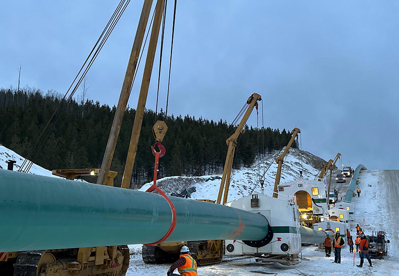

21.2.1 Double-Joint Welding
21.2.2 Mainline Welding
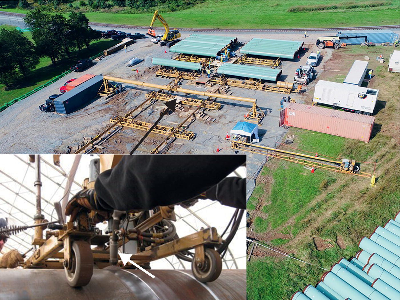
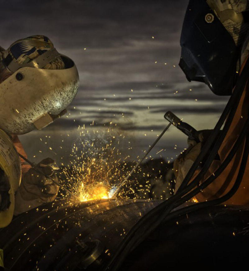

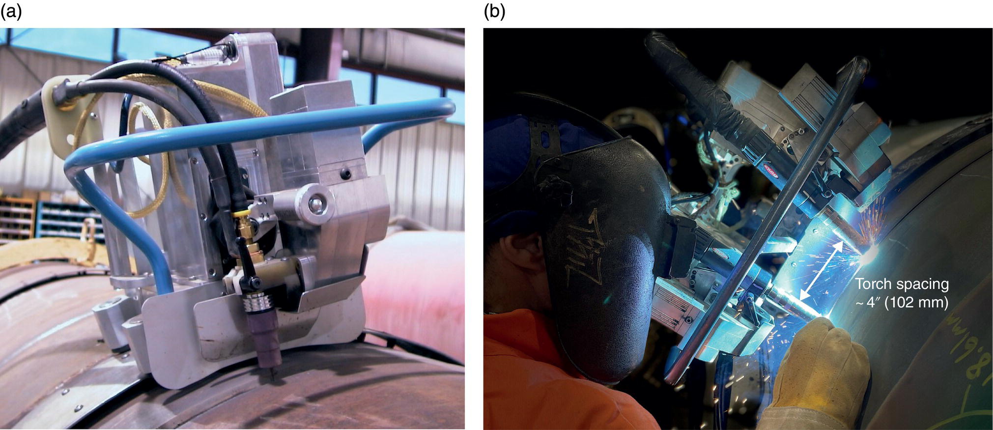
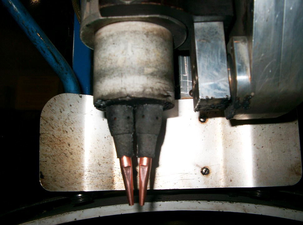
21.2.3 Tie-In and Repair Welding
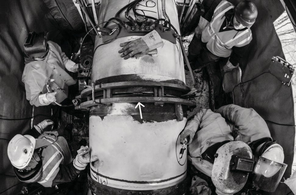
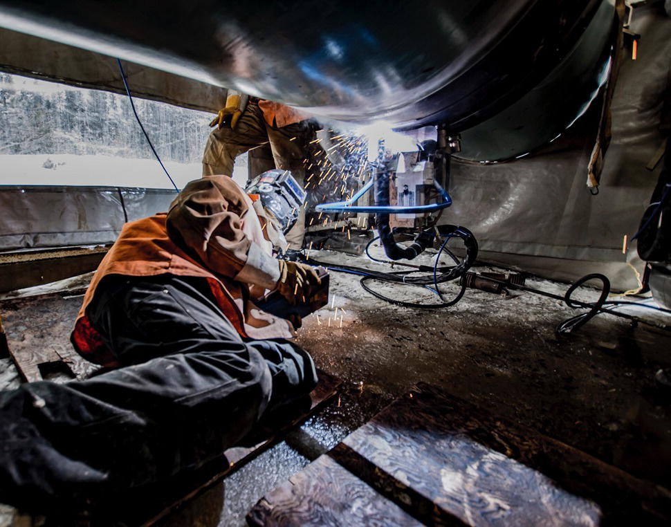
21.3 Nondestructive Inspection and Flaw Assessment
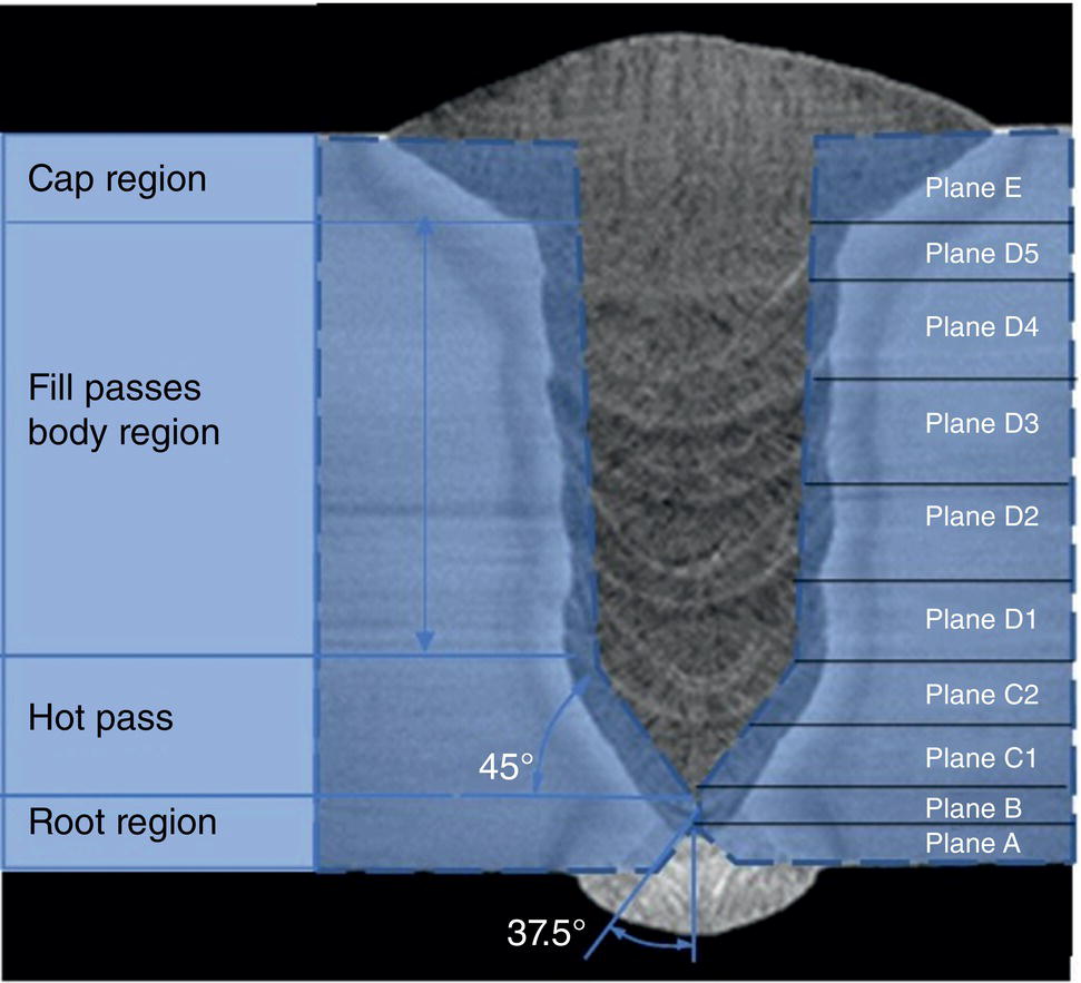
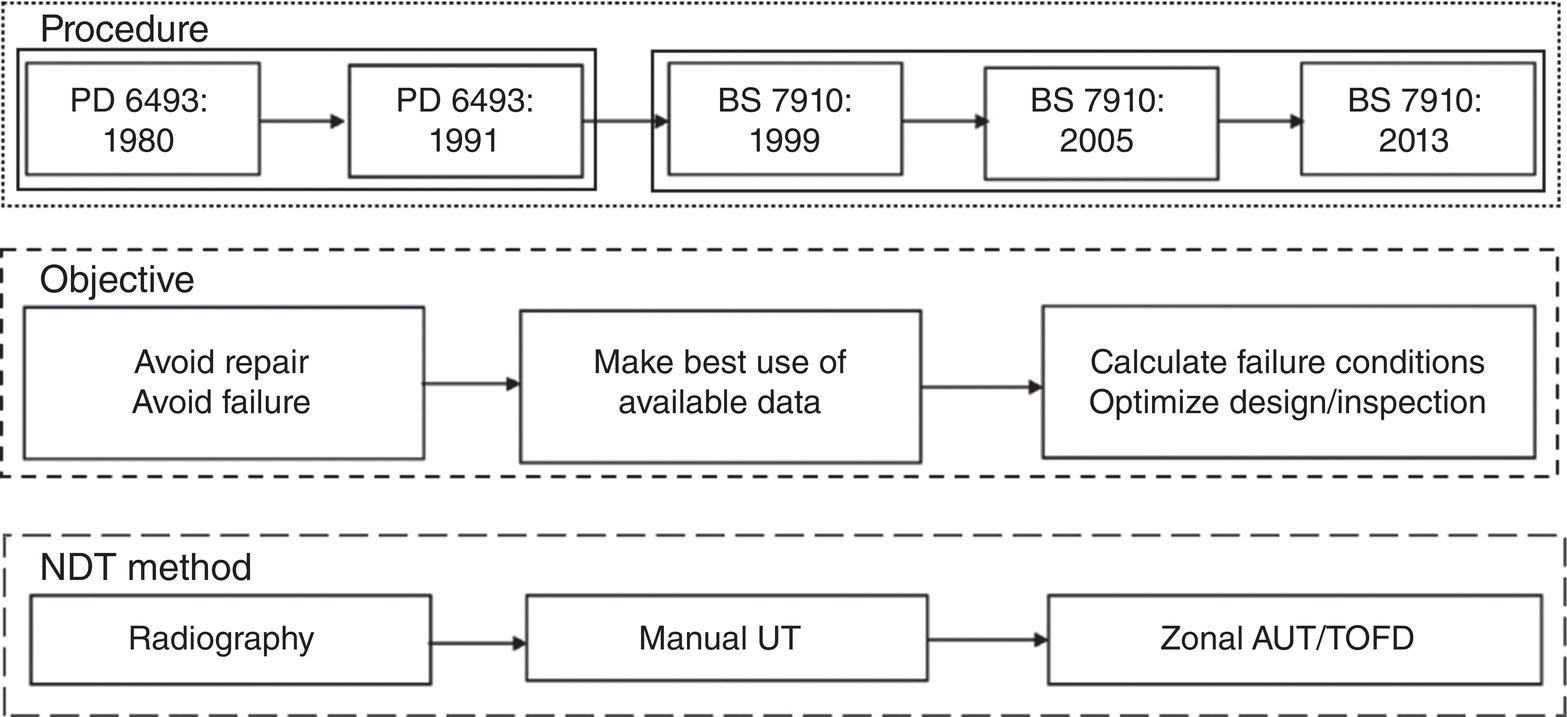
21.4 Welding Procedure and Welder Qualification
21.4.1 Welding Codes and Standards
21.4.2 Welding Procedures
21.4.3 Welding Procedure Specification
21.4.4 Procedure Qualification Record
21.4.5 Qualification of Welders
21.5 Hydrogen Control in Welds and the Prevention of Hydrogen-Assisted Cracking


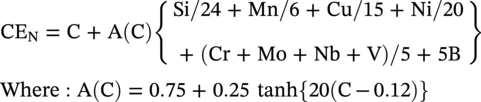
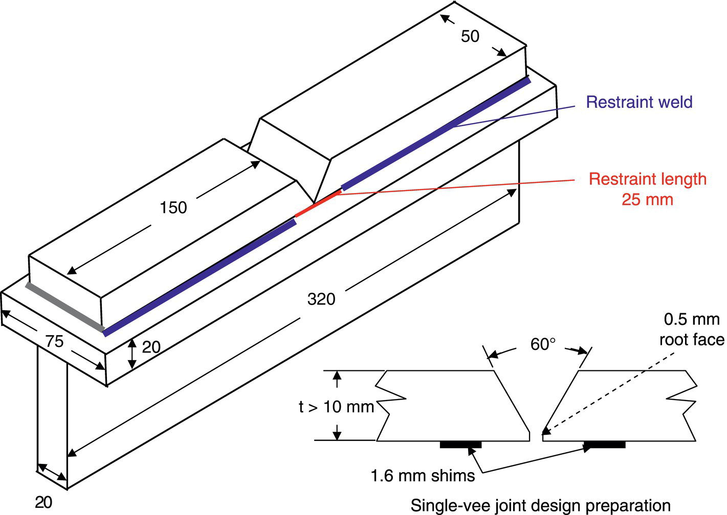
21.6 Important Considerations for Qualifying Welding Procedures to a Strain-Based Design
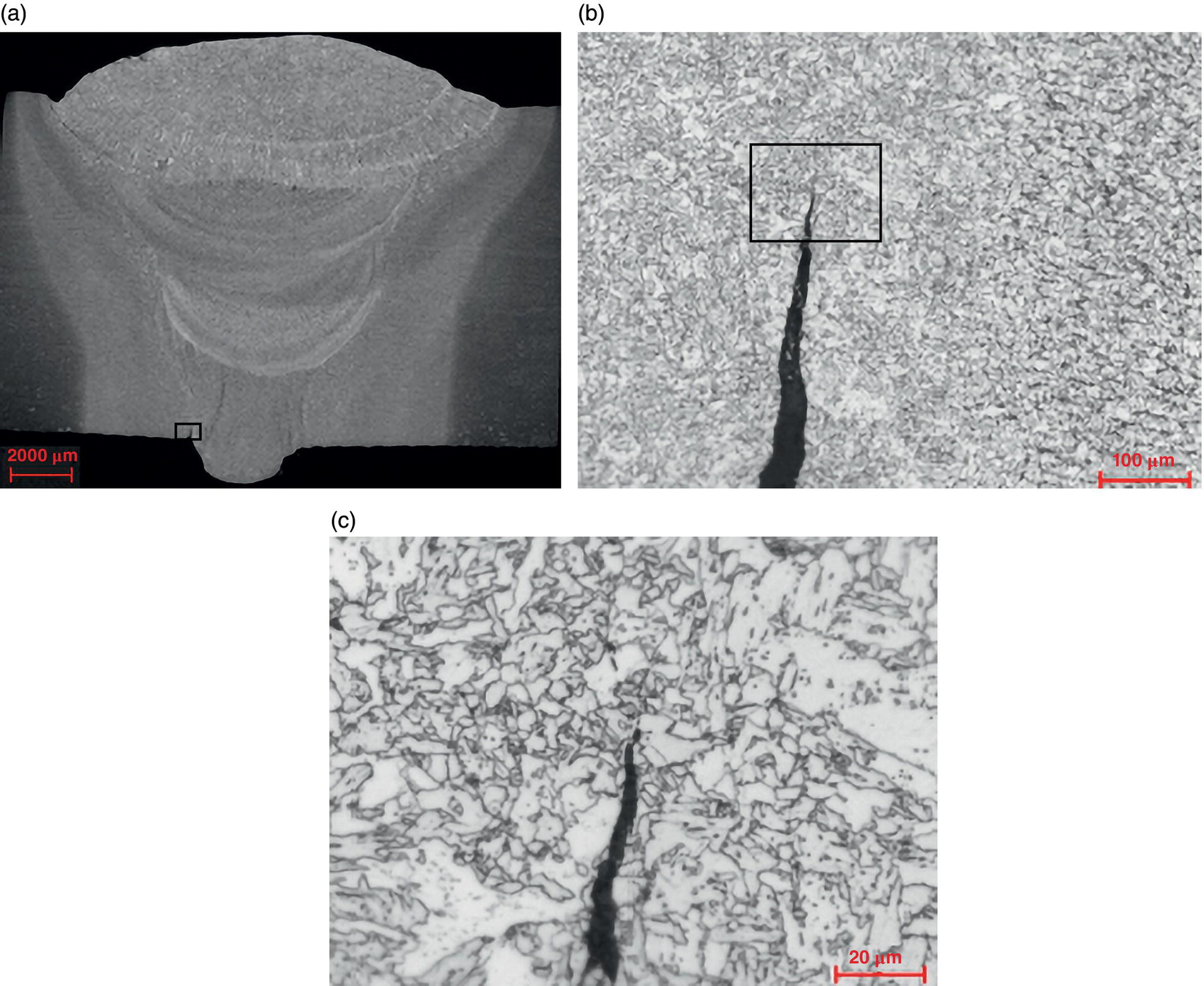
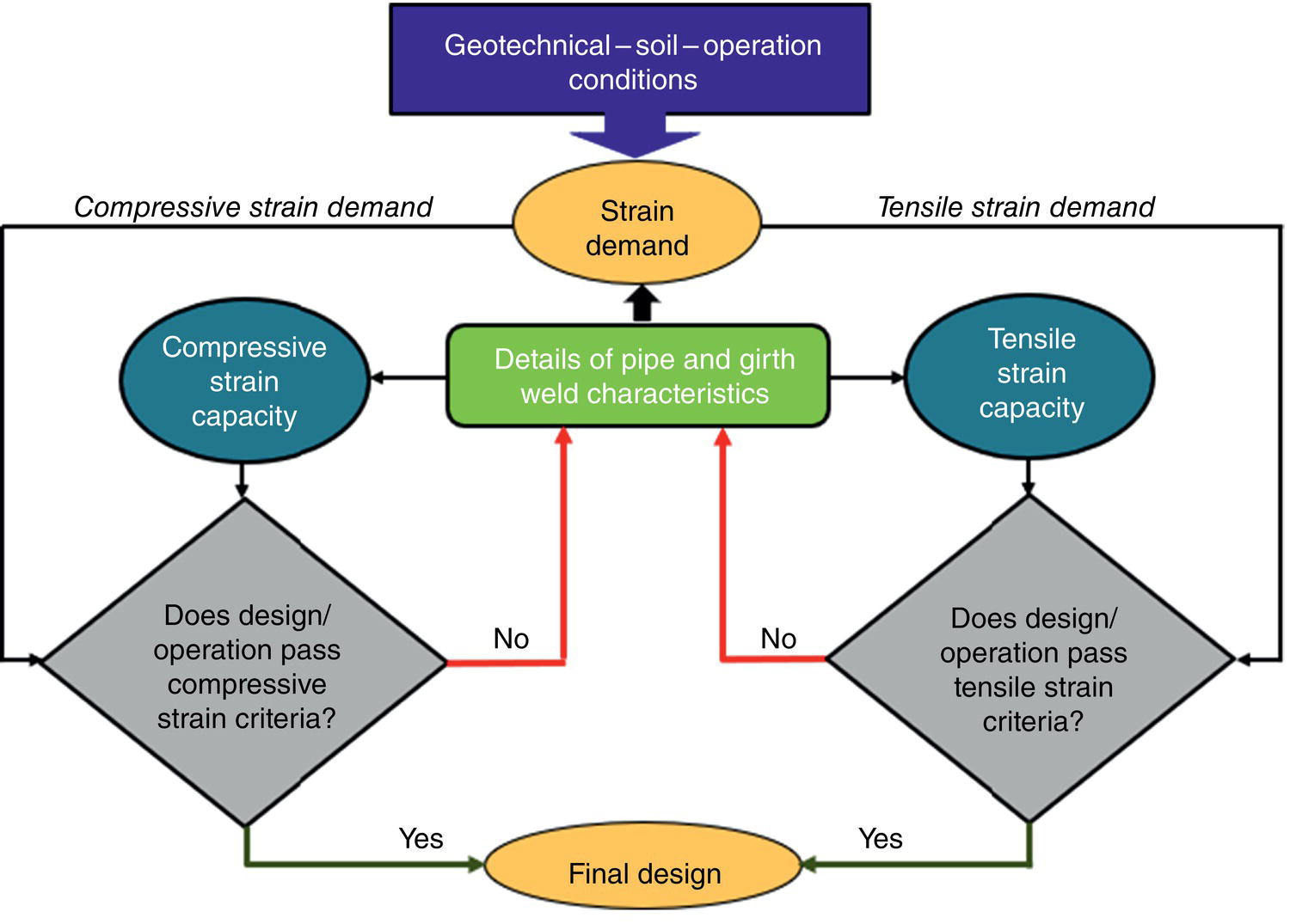
21.7 Welding on In-Service Pipelines
21.8 Pipeline Incidents and Recent Industry and Regulatory Preventative Action
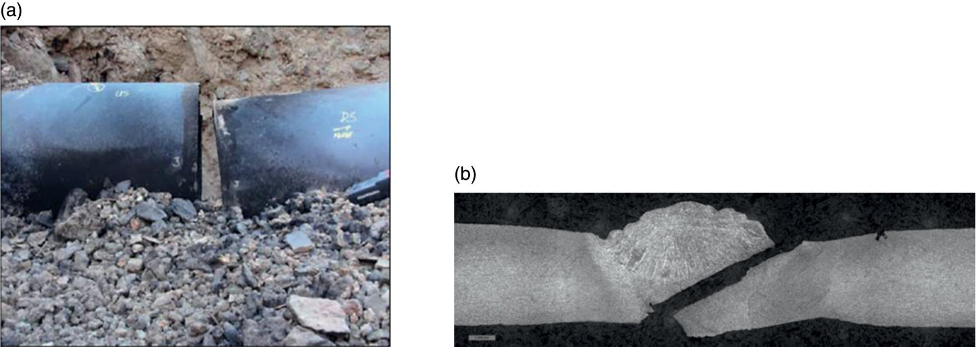

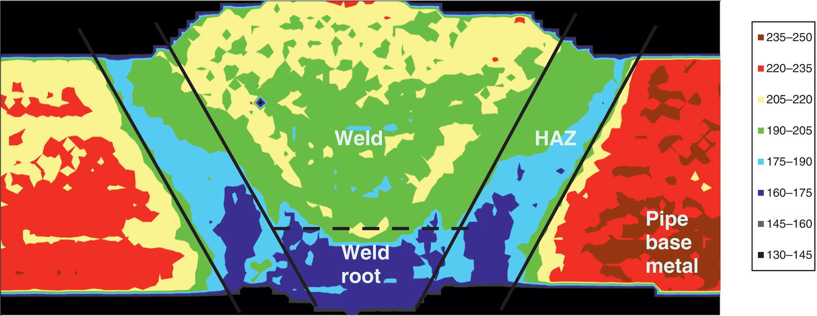
Acknowledgments
Appendix 21.A.1 Abbreviations Used in this Chapter
Term
Definition
Abbreviations for Units of Measurement
C
Celsius
g
Gram
HV
Vickers hardness
in
Inch
kJ
Kilojoules
km
Kilometer
kPa
Kilopascals
M
Meter
mL
Milliliter
mm
Millimeter
°
Degree
Abbreviations of Other Terms
API
American Petroleum Institute
Ar
Chemical element argon
ASME
American Society of Mechanical Engineers
AUT
Automated ultrasonic testing
AWS
American Welding Society
B
Chemical element boron
BSI
British Standards Institute
C
Chemical element carbon
CER
Canada Energy Regulator
CFR
Code of Federal Regulations
CMT
Cold metal transfer
Cr
Chemical element chromium
CSA
Canadian Standards Association
CTOD
Crack-tip opening displacement
Cu
Chemical element copper
CWP
Curved wide plate
CWT
Cross-weld tensile
ICWT
Instrumented cross-weld tensile
DNV
Det Norske Veritas
DOT
US Department of Transportation
ECA
Engineering critical assessment
ERW
Electric resistance welding
FCAW-S
Self-shielded flux-cored arc welding
FCAW-G
Gas-shielded flux-cored arc welding
GMAW-P
Pulsed gas metal arc welding
GMAW-S
Short circuit gas metal arc welding
HAZ
Heat-affected zone
HAC
Hydrogen-assisted cracking
MAOP
Maximum allowable operating pressure
Mn
Chemical element manganese
Mo
Chemical element molybdenum
NEB
National Energy Board is now Canada Energy Regulator
Ni
Chemical element nickel
NPS
Nominal pipe size
O
Chemical element oxygen
PHMSA
Pipeline and Hazardous Materials Safety Administration
PQR
Procedure qualification record
PRCI
Pipeline Research Council International
RMD
Regulated metal deposition
SBD
Strain-based design
SAW
Submerged arc welding
Si
Chemical element silicon
SMAW
Shielded metal arc welding
SMYS
Specified minimum yield strength
STT
Surface tension transfer
TMCP
Thermomechanical controlled processing
TOFD
Time-of-flight diffraction
V
Chemical element vanadium
WIC
Welding Institute of Canada
WPS
Welding procedure specification
Appendix 21.B.1 Regulations, Codes, and Standards
Reference
Description
API 5L
Specification for line pipe
API 1104
Welding of pipelines and related facilities
Reference
Description
ASME Section IX
BPVC Section IX—qualification standard for welding and brazing procedures, welders, brazers, and welding and brazing operators
Reference
Description
BSI 4515
Specification for welding of steel pipelines on land and offshore. Carbon and carbon manganese steel pipelines
PD 6493
Guidance on methods for assessing the acceptability of flaws in fusion welded structures
BSI 7910-2019
Guide to methods for assessing the acceptability of flaws in metallic structures
Reference
Description
CSA Z662-11
Oil and gas pipeline systems
CSA Z662-15
Oil and gas pipeline systems
CSA Z662-19
Oil and gas pipeline systems
CSA Z662-23
Oil and gas pipeline systems
Reference
Description
DNV-OS-F101
Submarine pipeline systems
Reference
Description
SOR/99-294
Onshore pipeline regulations, 1999
Reference
Description
49 CFR Part 192 Subpart E
Welding of steel in pipelines
References
Note
Pipeline Welding from the Perspective of Safety and Integrity
(21.1)
(21.2)
(21.3)