section epub:type=”chapter” role=”doc-chapter”> The last 20 years have seen a fast and steady increase of research into HTC. A quick survey with Scopus using the keywords “high temperature corrosion,” “high temperature oxidation,” and “high temperature coatings” showed that in 1995, 1335 papers were published and 13 620 patents applied for; in 2005, the figures increased to 4350 and 46 585, while in 2010 they increased to 7890 and 85 060, respectively. This is a direct result of the many investigations into high performance structural materials for aerospace, energy and automobile applications, and also long‐life corrosion‐resistant bulk and coating materials for engineering components working in complex environments, such as oxidizing, sulfidizing, carburizing, or chloridizing environments, with or without additional mechanical action of solid particles on the material surface. Metals and alloys must be effectively protected against these corrosive environments through the formation of protective oxide layers with the characteristics of slow growth, high resistance to cracking and spallation, and strong reheating ability. The prevention of high temperature corrosive attacks on materials plays a critical role in aspects such as reliability, quality, safety, and profitability of any industrial sector associated with high temperature processes (e.g. coal, oil, and fluidized‐bed systems, gas turbine and diesel engine systems, nuclear power systems, other power and energy generation and tribology sectors, and electronic and semiconductor components). There are many measures to protect the materials against their degradation at elevated temperatures, and some of them are described in the listed references. In particular, the excellent book Introduction to the High Temperature Oxidation of Metals, by Birks et al. (2006), describes a procedure concerned with the use of gaseous atmospheres to control surface reactions during reheating for working or heat treatment. Its main application is in this area of heat treatment simply to prevent surface damage, and the interested reader should study it for a deeper understanding of the subject. But the great stringent requirement of high temperature strength and corrosion resistance is a composite system in which mechanical strength is achieved by alloy development and corrosion resistance by surface coating or surface modification. Corrosion and oxidation protective coatings work by forming a thin oxide barrier on the surface as shown in Figure 18.1. This barrier separates the base metal and coating from the reactive gases. This barrier is extremely thin, on the order of 100 microinches or 2 μm. Without this barrier, the reaction gases would oxidize and corrode both the base metal and the coating itself. This oxide barrier is typically alumina, Al2O3, although chromia, Cr2O3, will also provide protection (chromium assists in the formation of the alumina oxide barrier). More recently, silicon is also being used as a beneficial oxide scale former. The role of the coating is to form this oxide barrier. Ideally, this barrier is perfectly adherent to the substrate, has no imperfections, and grows very slowly after first forming. Since one cannot achieve ideal oxide barriers, the coating must be able to reform the oxide barrier should some of it become damaged due to cracking, spallation, etc. The role of the coating is to act as a reservoir of the oxide‐forming elements, which are primarily aluminum and chromium. Thus, these coatings contain as much aluminum and chromium as possible. This chapter briefly deals with various coating systems and processes for their application, which are available for protection. Categories of coatings, methods of their production, brief considerations on their degradation, and present and future applications are also described. The need for coating systems in the domain of high temperature arose by the 1960s when improved performance criteria could not be met adequately in spite of new materials with superior physical, mechanical, and metallurgical properties. Operating efficiency and production economy had to be considered and an improvement sought. Figure 18.1 Scheme of a high temperature coating protecting the base metal by forming a protective oxide. In this section, a brief overview of the main categories of coating systems is provided. Nowadays the coatings for high temperature applications include mainly diffusion coatings, overlay coatings, and thermal barrier coatings (TBCs). The protective character of diffusion coatings attributes to the protective nature of the Al2O3, Cr2O3, and SiO2 scale formed, respectively, on the aluminides, chrominides, or silicides at elevated temperatures. Diffusion coatings have first been developed and still are the most used coating. Aluminide diffusion coatings are proved to be the cost‐effective solution for high temperature oxidation, which are used widely for protecting turbine blades and vanes. The properties of the aluminide coating depend on the process methodologies used to deposit the coating, the substrate composition, and the subsequent treatment. The coating deposition rate and morphology depend on the process temperature and time. Processing temperature influences the rate of diffusion, at which alloy elements may diffuse and the metallurgy of the surface compound may form; thus, it is a critical parameter in the processing and manufacturing of diffusion coatings. The coating time at temperature defines the thickness of the coating formed during the diffusion step. The thickness of the coating is also a main factor of protecting property of the coatings. Two basic mechanisms typify the diffusion coatings, depending on whether the main diffusing species is aluminum diffusing from the coating to substrate of the base metal of the substrate alloy diffusing outward to the coating layer. These coatings are usually produced by pack cementation, out‐of‐pack cementation, and chemical vapor deposition (CVD), which involve the diffusion of a predominant element such as aluminum to form “diffusion coating” layers. It should be noted that coatings are typically fine grained with more grain boundaries compared with substrate materials. Diffusion rates in coatings are therefore expected to be faster than in substrate of similar composition. The three main diffusion coating mechanisms will be analyzed in the next section. Here, the diffusion coating mechanisms will be briefly considered, taking the diffusion aluminide coatings as an example. Aluminizing is achieved by two different processes that are based on the activity of aluminum in the gas phase and the aluminizing temperature. The low activity high temperature (LAHT) process is a “one‐step” method with outward diffusion of Ni to form β‐NiAl coating. On the other hand, the high activity low temperature (HALT) process concerns the inward diffusion of aluminum, typically giving rise to a δ‐Ni2Al3 coating, which requires subsequent heat treatment to convert it to β‐NiAl. This is because δ‐Ni2Al3 is a brittle phase that has lower mechanical property than β‐NiAl. As might be expected, the mechanisms by which the coatings grow are also different. For the LAHT process, the aluminum activity is insufficient for it to be the predominant diffusing species, and accordingly, coatings form by diffusion of Ni from the alloy substrate into the region of the coating. For the HALT process, the aluminum activity in the gas phase and at the surface of the coating is high enough to facilitate the inward of Al into the alloy substrate. The growth mode is an important factor when considering coating integrity, since coatings formed by outward Ni diffusion can trap diluent particles (alumina) brought by aluminizing packs. While in the coating β‐NiAl phase layer of LTHA, much unwanted phases can precipitate dispersively, which decrease the mechanical property of the coating. Which coating process is selected depends upon a number of features, e.g. heat treatment specifications for the substrate alloy, applications, nature of packs available, integrity issues, etc. In LAHT aluminizing (low aluminum content in the pack [1.2–1.5 wt% of Al], 900–1150 °C), the aluminum is deposited on the surface, but at reduced rate, and nickel simultaneously diffuses outward to the surface. Then a β‐NiAl surface layer forms. The interdiffusion coefficient in the β‐NiAl phase of the Al–Ni system varies strongly with composition. At 1050 °C, the minimum value of interdiffusion coefficient is not at the stoichiometric composition, but displaced to the low‐Al side by 1–2 at.% (that is 48–49 at.% of Al). Ni diffuses predominantly in low‐Al β‐NiAl. The rapid nickel diffusion to the surface, coupled with the low aluminum activity at the surface, effectively holds the surface aluminum content close to 50 at.%. Hence, LAHT coatings are near stoichiometric at the surface and Ni rich within the substrate β‐NiAl phase. This structure ensures outward of Ni transport and the outward growth of the coating microstructure. Another important result is that slowly diffusing elements Ta, W, Re, and Mo from substrate are unable to diffuse to form significant concentration levels in the outwardly growing β‐NiAl. The outer zinc zone of this coating therefore appears much “cleaner” and is free from such precipitates as observed in the HALT coatings. The limited solubility of Cr, as well as Ta, Mo, and W, in the β‐NiAl phase produces precipitates of topologically close‐packed (TCP) phases, forming an interdiffusion zone (IDZ) under the “clean” β‐NiAl phase layer. Thus, the IDZ includes the complicated TCPs and β‐NiAl phases. This coating composition and structure are less dependent on the alloy composition. The further diffusion processes between such aluminide coatings and Ni‐based alloys are determined by the aluminum activity in the β‐NiAl phase. As long as this is lower than the equilibrium activity among β, IDZ, and γ + γ′ matrix, Ni will diffuse out of the base alloy into the β phase. The coating grows further outward. The kinetics of the formation of aluminide coating on pure Ni by LAHT has also been studied, and this mechanism is illustrated in Figure 18.2. Figure 18.2 Diffusion aluminide formation on pure Ni. In respect to the HALT theory interpreted above, if the activity of Al is low, Ni preferentially diffuses out through the coating and combines with Al to form NiAl. The coating grows outward. In this case, Ni diffuses faster than inward diffusion of Al. Pack particles are entrapped in the coating. These particles are assumed to be dragged out by the diffusion of Ni. As previously mentioned, HALT coatings are processed at lower temperature (700–950 °C) as the first step, with a higher aluminum content (1.7–2.7 wt% of Al). The substrate material (γ‐Ni + γ′‐Ni3Al) reacts with the depositing aluminum, forming a surface layer of δ‐Ni2Al3 over the layer of β‐NiAl. The diffusivity of Al through δ‐Ni2Al3 is very high, and substantial amounts of Al can be forced deeper and deeper into the material. In δ‐Ni2Al3 phase layer, the diffusivity of Ni is near zero, while Al diffuses rapidly; thus the formation of surface layer of δ‐Ni2Al3 results from the inward diffusion of aluminum. Substrate alloying elements such as W, Mo, Ta, and Re are selectively diffusing at the coating/substrate interface. Once the solubilities of alloying elements of W, Mo, Ta, Re, and Cr are saturated, many precipitates rich in these elements will occur for their limited solubility to β‐NiAl phase and distribute in the entire coating structure. After a second step of heat treatment at higher temperature (950–1100 °C), Ni is able to diffuse outward to transform the brittle δ‐Ni2Al3 phases into Al‐rich β‐NiAl. This step is also usually combined with the heat treatment required to recover substrate properties. Now we have preliminary concepts of LAHT and HALT, and then we can primarily establish whether the coating belongs to one process or the other. However, in the actual manufacturing there are all kinds of operations by adding different amounts of Al and at different temperatures. Therefore, the resulting coating could be significantly different and have very complex structures. Coating–superalloy interdiffusion is principally responsible for the phase transformations, oxidation behavior, and degradation of the mechanical properties of the coating. Moreover, the diffusion behavior in the multicomponent coating layers is very complicated due to the interactions among the components. Thus, diffusion is an important factor to be considered when designing β‐NiAl coatings. Diffusion‐type coatings, used successfully on early gas turbines, were tied to the substrate composition, microstructure, and design. Later, some changes were introduced: (i) in superalloy composition, such as reduction in Cr and increase in other refractory metals; (ii) in microstructure, by castings with more segregation; and (iii) in design, by air cooling and with thin walls (which introduced higher thermal stresses). These changes required coatings that were much more independent of the substrate. Overlay coatings met this necessity. Overlay coatings also overcome the process restrictions encountered in diffusion coatings, especially the variants, viz. Cr/Al, Ta + Cr, or the Pt aluminides, all of which give better stability and oxide hot corrosion resistance than Al alone. MCrAlY compositions (M = Ni, Co, Fe alone or in combination; Y represents oxygen‐reactive elements such as Zr, Hf, Si, and Y) are the principals in the series of overlay coatings developed by the electron beam evaporated physical vapor deposition (EBPVD) technique for multiple load use. More than 4 million aerofoils have been successfully processed by EBPVD. MCrAlY overlay used in gas turbines are usually Ni and/or Co with high Cr, 5–18% Al, and Y addition around less than 1% for stability during cyclic oxidation. They are multiphase alloys with ductile matrix, e.g. gamma Co–Cr, containing a high fraction of brittle phase, e.g. beta CoAl. The Cr provides oxidation hot corrosion resistance, but too much Cr affects substrate phase stability. The success of most overlay coatings is the presence (and perhaps location) of oxygen active elements such as Y and Hf, which promote alumina layer adherence during thermal cycling, giving increased coating protectivity at lower Al levels. Y mostly appears along grain boundaries if a MCrAlY is cast but is homogeneous if plasma sprayed. Thus MCrAlY with 12% Al are more protective than the more brittle diffusion aluminides with 30% Al. Overlay claddings deposited by hot isostatic pressing (HIP), electron beam evaporation, or sputtering methods are diffusion bonded at the substrate/coating interface, but the intention here is not to convert the whole coating thickness to NiAl or CoAl. There is thus more freedom in coating composition, whose properties can be maximized to the type required. Composition based on NiCr, CoCr, NiCrAl, CoCrAl, NiCrAlY, CoCrAlY, FeCrAlY, and NiCrSi have been successful in gas turbine engines. They are generally alumina formers with only 10% Al unlike the 30% in nickel aluminide coatings. Cr increases the Al activity, which allows this feature. Higher Al levels cause brittleness and a higher DBTT, and the Al levels are generally held below 12% (5–10% preferred). The coatings are also more ductile than NiAl and CoAl and can be rolled and bonded by HIP. In general, NiCrAlY give best results against high temperature oxidation, while CoCrAlY are best for hot corrosion. TBCs are ceramic coatings applied over metal substrates to insulate them from high temperatures. They consist of zirconium oxide, ZrO2, stabilized by about 8 wt% yttria, Y2O3, or magnesia, MgO. They are applied over a bond coat that is usually an MCrAlY overlay coating but can be a diffusion coating. The ceramic layer is typically 5–15 mils thick, and the overlay bond coat is usually 3–8 mils thick. The bond coat improves the adhesion of the ceramic top coat by reducing the oxide buildup underneath the ceramic. (The ceramic is porous to oxygen and will spall off when the oxide formed on the bond coat is sufficiently thick.) The bond coat is applied in the same manner as for overlay coatings. The ceramic layer is normally plasma sprayed in an air environment. This layer can also be made by electron beam physical vapor deposition (EBPVD), which is used on aircraft engines. The ceramic layer made by EBPVD is columnar grained and is more resistant to spalling than the plasma‐sprayed TBC. Another type of ceramic layer that has been developed is called a segmented TBC. It has cracks through the thickness of the ceramic, which are perpendicular to the substrate surface. These cracks provide increased resistance to spallation, similar to EBPVD ceramic layers. The segmented TBC is made by a proprietary plasma spray process, and very thick ceramic layers can be made. The TBC protects the metal by acting as an insulator between the metal and the hot gases. The thermal conductivity of the ceramic is 1–2 orders of magnitude lower than the metal. Although thin, the TBC can significantly reduce the metal temperature provided that the metal component is air cooled. (The air cooling provides a heat sink.) Furthermore, the ceramic has a higher reflectivity than the metal. This means that more of the radiative heat is reflected away, which is important for combustion hardware. During startup and shutdown, the TBC improves the thermal fatigue life by reducing the magnitude of the temperature transients the metal is exposed to. A 10 mil thick TBC on airfoils in experimental aircraft engines has achieved more than 300 °C reduction of metal temperature. During steady‐state operation, the TBC lowers the temperature of the underlying metal, thereby improving its durability. It also reduces the severity of hot spots. The principal failure mechanism of TBCs is the spallation of the ceramic layer. Spallation is caused by the synergistic interaction of bond coat oxidation and thermal cycling. The oxidation occurs at the interface between the bond coat and the ceramic. As more oxide forms at this interface, the ceramic layer is more likely to spall. There are three major processes by which the diffusion coatings can be formed: CVD, pack cementation, and out‐of‐pack cementation, which involve the diffusion element such as aluminum (chromium or silicon). Overlay coatings can be applied by CVD, physical vapor deposition (PVD), high velocity oxygen/flame (HVOF), or plasma spray. Plasma spray is one of the most widely used processes today. TBCs are usually deposited by PVD, EBPVD, and plasma spraying techniques. All these processes and a few more advanced techniques for producing high temperature coatings are described in this section. CVD is a process wherein a stable solid reaction product nucleates and grows on a substrate in an environment where a vapor‐phase chemical dissociation or chemical reaction occurs. It uses a variety of energy sources, viz. heat, plasma, ultraviolet light, etc., to enable the reaction and operates over a wide range of pressures and temperatures. CVD is a long‐established, economically viable industrial process in the field of extraction and pyrometallurgy. Some of the well‐known processes are: The method has also been used to form freestanding, simple, and complex shaped articles from metals that are not very amenable to fabrication, e.g. W: The technology of CVD took on new dimensions with a fresh view taken at the deposition aspects of the process. This transition of emphasis from extraction to deposition of the CVD phenomenon has made CVD an important sector of coating technology for producing new materials and coatings with improved resistance to wear, erosion and corrosion, good thermal shock resistance, and neutron absorption characteristics. Components from micro‐ to macro‐sizes are now coated by CVD. In the deposition area of CVD, the lamp and electronics industry uses many of the earlier processes to obtain longer service life and better performance for a number of products. The CVD industry took a bigger leap when demands arose for new high temperature materials with greater high temperature corrosion resistance and strength in all the sectors using gas turbines and other propulsion hardware, in the military science, engineering, and aviation fields. In parallel, CVD technology has had rapid application in the semiconductor industry, the many branches of fuel and energy – nuclear, fluidized bed, oil, solar and chemical industries and the tool industry. Solid‐state devices; electrode materials; thermionic devices; erosion‐, corrosion‐, and wear‐resistant components; fission barriers; and many more applications can be listed in CVD technology. It would be confusing and misleading to list a number of processes as CVD methods in as much as different high temperature coatings cannot be merely termed as diffusion coatings. The minor or major parameters that influence the actual achievement of the coating itself are those that facilitate categorization. Otherwise, conventional CVD, plasma‐assisted CVD (PACVD), laser‐assisted CVD (LACVD), pack, vacuum pack, pack‐slip, vacuum pack‐slip, CCRS, or RS may all be just CVD. Similarly, diffusion coatings can be obtained by first hot dipping, spraying, cladding, fused salt electrodeposition, electrophoresis, plasma, or all PVD, and all the above “CVD” methods. What gives the distinction to any process? The obvious factor that emerges is that a basic CVD process has a number of limitations, e.g. the types of reactions possible and available, and the minimum substrate temperature that has to be maintained. This results in restricting any eventual substrate/deposit configuration and control. Improved techniques stretch the reactant–product spectrum and can also (i) lower the temperature; (ii) reduce the hazards and mismatch in the morphological aspects, viz. nucleation and growth; (iii) alter the physical–mechanical properties favorably; and (iv) provide better bonding. CVD technology offers the following favorable aspects to semiconductor industry: A wide range of metallic and inorganic coatings can be produced by CVD. In many instances CVD coatings exhibit unique properties, which are difficult to produce by other methods. A CVD process was seen as a thermochemical process in which the substrate is regarded as a collector of the deposit, and the substrate/deposit interaction is both undesirable and unnecessary for deposit growth. However, for a CVD deposit, the post‐deposition state is a mandatory parameter to meet the service requirements; substrate/deposit interaction to some degree is expected. Further, heat treatment, and therefore diffusion, is often a step following the primary CVD process (or even during deposition, since the substrate is heated). Thus, substrate/deposit interaction always occurs and is also one of the ways deposit consolidation can be achieved. A CVD reactor is the apparatus‐equipment configuration that carries out the CVD process. CVD reactors are categorized on the basis of the temperature and pressure under which they operate. A CVD reactor can have a cold wall or a hot wall depending on the experimental optimization parameters. When the reactor wall surrounding the heated substrate is comparatively cool relative to the temperature of the substrate, it is a cold‐wall reactor. The substrate is heated directly, and product deposition occurs mostly on the heated component. In a hot‐wall reactor, the deposition product can nucleate both on the reactor wall and the heated substrate, though to different degrees, if a temperature difference prevails across the wall substrate area and zone. The substrate may be independently heated or not, but the reactor itself is heated in order to facilitate the process. The CVD reactor assembly consists of three components: (i) the reactant supply system, (ii) the deposition systems, and (iii) the reactant–product retrieval, recycle, and disposal system. The entire reactant supply (using solid and/or gaseous reactants) has to be carefully balanced before introduction into the reactor system, predicted to reach the required partial pressures at the temperatures of reaction and deposition. The primary features to consider concerning the substrate are the substrate/deposit adherence and growth. CVD reactions can be exothermic but mostly are endothermic. This could result in substrate cooling. On a production scale, large volumes of gases are handled, which can induce convective coating. Both these situations have to be compensated. Substrate heating optimization involves achievement of the correct temperature profile and coating exposure time. The substrate/reactor parameters in a deposition system should be designed to achieve a laminar flow. The input can be parallel, perpendicular, or angular to the substrate depending on the substrate holder design. The movement (rotation, lateral, etc.) of the substrate within this region also compensates to some extent any nonuniformity in the deposition. CVD occurs through a chemical reaction; therefore, the thermodynamics of the system that can drive the chemical reaction, the basic chemical kinetics to provide information on the reaction rate, and mass and heat transfer profiles that are influenced by the reactor and substrate size and design, require consideration. Mass transport of a CVD system links diffusion control, chemical kinetics, and fluid‐flow dynamics. Diffusion growth can be ascertained from chemical kinetics by rate constant of growth = A exp (−E/kT), where E is the activation energy, k is the Boltzmann’s constant, and T is the temperature. With increase in substrate temperature, the growth rate changes at a transition temperature from a predominant kinetics to a diffusion control, the latter being mostly under mass transport influence (Figure 18.3). Figure 18.3 Growth rate curve of a CVD process – schematic. Many models of CVD reactors and their kinetics have appeared in the recent literature, but space restrictions impose our departure to the next coating process. Pack cementation is an extended CVD method in which the substrate to be coated is introduced in a retort and surrounded by a powder mixture, which is composed of the source alloy(s), an activator, and an inert filler. The retort is then heated to the desired coating temperature usually under inert or reducing environment. In these conditions, the source element reacts with the activator, forming a gaseous transporting species. This diffuses through the pack to the substrate surface where it decomposes, allowing the metallic element to be deposited to penetrate into the substrate by solid‐state diffusion. As for all diffusion coatings, the microstructure is highly dependent on the substrate, which is coated. For this reason, process conditions have to be optimized for each material. The first “cementation process” was presented by Allison and Hawkins in 1914, who deposited Al on iron and on steel. But it is only since the 1960s that this process stimulated interest because of the development of coatings for the protection of gas turbine blades, especially those made of Ni‐based superalloys. The process has then been extended to Co and Fe‐based alloys. Concerning the elements deposited, these are mainly Al followed by Cr and Si. Nevertheless, codeposition of two or three elements became possible with the theoretical understanding of the process. The extensive works on Cr–Al codeposition published by Rapp on steels (1989, 1994, 1997) and by Young et al. on nickel‐based alloys (da Costa et al. 1994a,b, 1996; Gleeson et al. 1993) are the major examples, but development of Cr–Si (Rapp 1996), Al–Si (Wynns and Bayer 1999), Ti–Al (Weber 2004), and Ti–Si–Al (Rosado and Schütze 2003) coatings can also be mentioned. Eventually, more recent investigations seem to focus on the addition of reactive elements such as Y, Ce, or Hf by codiffusion. The principles of the pack cementation technique changed remarkably little since 1914, but the composition and the quality of the substrate–deposit systems have been optimized in reply to the requirements of a large range of service applications. From an industrial point of view, the pack cementation technique has been used very extensively for nearly 60 years for coating gas turbine blades (Mévrel et al. 1986). Nowadays it is estimated that on first‐stage gas turbine blades, more than 80% of all coated airfoils are coated by pack cementation (Goward 1998). Table 18.1 Different pack mixes and processing parameters for various pack cementation coatings The coating of larger pieces has been the subject of some research investigations and even leads to the development of a few patents, showing that coating even inside a tube is possible by this technique (Baldi 1980; Wynns and Bayer 1998). During the 1990s the US company Alon developed several industrial processes involving the pack cementation technique. The purpose was to protect ethylene cracker furnace components from carburization and coke formation (Kurlekar and Bayer 2001). With Alon’s facilities, 15 m long furnace tubes can be coated with Al, Cr, and/or Si on an industrial scale, producing 100 000 linear meters of tubes per year (Alon). After one year service in an ethane cracking furnace, the coating reduced the coke formation by a factor of 2, and post‐exposure analysis revealed that the coating microstructure was essentially unchanged (Ganser et al. 1999). Typically the powder pack mixture consists of three components: Table 18.1 lists different packs that can coat various elements with the corresponding temperatures and heat treatment durations. Figure 18.4 illustrates the major chemical reactions involved in the general pack cementation process. In order to allow a better understanding of the following paragraph, the reactions are written for the particular example of aluminizing of iron activated by NH4Cl. Figure 18.4 The main chemical reactions involved in the pack cementation process. The whole process relies on the formation of gaseous halides according to the general reaction: AlCl3, AlCl2, AlCl, Al2Cl6, and Al2Cl4 are the chlorides involved in a chloride‐activated aluminizing process. The partial pressures of each of the gaseous halides formed are established by their thermodynamic stability, which varies with the process conditions: composition of the pack, type of activator, temperature, pressure, and type of inert or reducing environment. In the case of aluminum deposition, AlCl3 is the major halide formed at low temperature, whereas at higher temperature the activity of AlCl becomes higher. Once they are formed, the halide molecules diffuse through the gas phase to the substrate (e.g. iron) surface, where they adsorb and decompose owing to the general reactions: By using alkaline or earth alkaline halide activators as, for instance, NaCl, KCl, or CaCl2, the precipitation of the activator salt has also to be considered (Ravi et al. 1989): The aluminum formed at the surface of the substrate of Reactions 18.6–18.10 can then diffuse into the solid substrate, forming the desired coating. The predominance of the Reactions 18.6–18.10 depends, first of all, on the stability of the gaseous halides involved. The deposition particularly occurs by disproportionation Reaction 18.6 when, first, the vapor pressure of the substrate halide is low and when, secondly, the coating element has higher and lower halides of comparable vapor pressures in order to set atomic aluminum‐free. When the vapor pressure of the substrate halide becomes comparable to the gaseous species of the coating element, the contribution of the exchange Reaction 18.7 becomes important. The latter reaction even gets undesirable if the vapor pressure of the substrate halide becomes higher than the source supplier halide, as it would lead to a significant metal loss and to porous coatings. In a NaCl‐activated pack, this phenomenon can occur during chromizing or siliconizing of iron, whereas Reaction 18.7 stays minimal during aluminizing (Kung and Rapp 1989). The reader may, at this point, easily catch the compromise that has to be found. Because halide molecules must diffuse through the gas phase from the pack to the substrate, the coating composition depends on the gaseous halide activity and their stability or their ability to decompose at the substrate surface. Hence, the formation and the decomposition of the gaseous halide have to be optimized at the same time in the pack and at the substrate surface, respectively. Furthermore, it is a prerequisite that the thermodynamic activity of the incorporated element is always lower at the surface than in the pack (Gupta and Seigle 1980). This activity gradient drives the gas‐phase diffusion of the halide molecules from the pack to the substrate surface. As a consequence, a desired coating composition cannot be obtained by simply using a master alloy of the same composition (Rapp 1989). Moreover, the concept of “major depositing species” has been defined. This corresponds to the gaseous species that is responsible for the major part of the deposition. In the case of a Cr–Al codeposition process by a chloride‐activated pack, Rapp (1989) and da Costa et al. (1994a,b) showed that although the vapor pressure of AlCl3 is several orders of magnitude higher than that of Cr halides and other Al halides, the codeposition is possible by optimizing the process conditions so as to get comparable vapor pressures of AlCl and CrCl2. Indeed, AlCl3 is too stable and does not decompose enough at the substrate surface. The Al transport occurs via AlCl. This is thus considered as the major transporting species for Al, whereas CrCl2 is the major transporting species for the deposition of Cr (Rapp 1989). The formation of the coating can be described in the light of diffusion couples (Wachtell 1974). The coating actually corresponds to the IDZ between the substrate element(s) and the deposited element(s). The driving force for the solid‐state diffusion is the activity gradient between the pack/coating and the coating/substrate interface. The aluminizing of iron can thus be treated as a binary diffusion couple, involving pure Al and pure Fe. As a consequence, the phases formed in the coating should follow the FeAl binary phase diagram (Figure 18.5). Figure 18.5 FeAl phase diagram. Source: Massalski (1986). Figure 18.6 Simplified scheme of the two archetypes of pack cementation aluminizing structures on Ni drawn on the basis of Goward and Boone’s work (1971). JAl and JNi designate the fluxes of Al and Ni, respectively. (a) High activity pack structure inward diffusion of coating element(s) at low temperature. (b) Low activity pack structure outward diffusion of substrate element(s) at high temperature. Figure 18.7 A nickel aluminide diffusion coating produced using LAHT pack cementation process. Figure 18.8 A nickel aluminide diffusion coating produced using LTHA pack cementation process on CMSX4. Source: Das et al. (1998). As can be seen from this diagram, the aluminizing of iron can form several intermetallic phases, FeAl3, Fe2Al5, FeAl2, FeAl, or Fe3Al as well as solid solution of Al in Fe. The effective formation of these phases is however controlled by the powder composition, the temperature, and the duration of the process. These parameters especially control the diffusion fluxes, which determine the final coating structure. Goward and Boone (1971) distinguished the low and the high activity pack structures (Figure 18.6), as already discussed in Section 18.2.2. Their investigations considered the aluminizing of a nickel‐based superalloy. Two powder pack mixtures differing in the nature of the Al source (pure Al or Ni2Al3) were investigated at about 800 and 1100 °C, respectively. The observations lead the authors to consider that the high activity pack (with the powder containing pure Al) structure is characterized by a high aluminum content at the surface with the coating phase Ni2Al3. The underlying phases down to the coating–substrate interface followed the Ni–Al phase diagram with decreasing Al content. For the low activity pack (with the powder containing Ni2Al3), the coating is single‐phased β‐NiAl, which is directly in contact with the substrate. The difference was attributed to the diffusion fluxes: One example of nickel aluminide diffusion coating produced by LAHT pack cementation process is illustrated in Figure 18.7. The coating consisted of a well‐defined to “clean” layer with NiAl as its major phase and a large diffusion zone underneath. An example of SEM‐BSE (backscatter electron) image of LTHA coating on Ni‐based superalloy CMSX4 (this is a typical second generation Ni‐based single‐crystal superalloy characterized by the replacement of most of the Ti with Ta, by relatively high Co and low Mo content) is shown in Figure 18.8. This coating was deposited using an aluminizing pack containing 2 wt% Al at 900 °C and was heat‐treated for 2 hours at 1120 °C and then for 24 hours at 845 °C. The β‐NiAl phase layer is uniform in thickness, and many precipitates (white small particles) distributed dispersively in the entire β‐NiAl phase layer. Squillace et al. (1999) has also analyzed clearly the coating structure after the first step of LTHA. Three layers are visible: the inner layer has a striated appearance, the outer layer is equiaxed with many inclusions, and the middle layer is featureless. The coating layer has deposited very high amount of Al. In the book entitled High Temperature Coatings by Bose (2007), it was presumed that higher inward diffusion of Al with lower outward Ni diffusion has avoided the formation of Kirkendall porosity and also eliminated the embedded pack particles. Although mixed types of mechanisms can occur as a result of varying pack activities, substrate compositions, and temperature, during practical application of the coating process, it is still of great use nowadays to relate the observed structures to two archetypes (Figure 18.6). The aluminizing of iron shows the same kind of behavior. At 900 °C, a three‐layer structure with Fe2Al5, FeAl2, and FeAl is formed in high activity packs, and a single‐phased FeAl coating in low activity packs (Levin et al. 1998). With the help of thermodynamic calculations performed with a computer software, the activities of the gaseous halides can be determined considering all pack reactions together. Such considerations allow the optimization of the pack concentration and process conditions needed to form the desired coating phase. More precisely, the activities of the gaseous halide depend on the reactants involved in the halide formation and thus on the type of metallic source mixed to the pack powder. Therefore, the direct dependence of the coating structure with the master alloy determines whether the coating deposition occurs in a high or low activity process. The activator is also a determining reactant involved in Reaction 18.5 too, from which it can be said that an unstable activator results in high halide partial pressures. Moreover, concerning the choice of cation for the activator, some researchers recommend the use of ammonium salts, because of their decomposition at high temperature. Indeed, the NH3 produced in Reaction 18.5 is not stable above 350 °C decomposing by the following reaction: which shows a double advantage: Concerning the thermodynamic aspects of pack cementation, it is also necessary to note that as a consequence of the temperature dependence of the Reactions 18.5–18.11, the process temperature directly influences the formation of gaseous halides and their decomposition, as well as the values of the gaseous and solid‐state diffusivities that also influence the kinetics of the cementation process. Like all CVD processes, pack cementation involves gas–solid reactions. For many cementation coatings, the coating process can be considered as six steps in series (Cockeram and Rapp 1995). Usually at the beginning of the process, the flux of master alloy element delivered by halide molecules on the surface is slower than the limiting flux of this element dictated by the solid‐state diffusion. Consequently, the beginning of the process follows the gas diffusion kinetics, and the growth of the depleted zone is rate limiting. At the end of the transition regime (regime after which equilibrium in the pack is achieved), the aluminum flux delivered by the gas phase equals the maximum uptake into the solid phase. At that moment, the kinetics limitation of the process changes from gas diffusion to solid‐state diffusion. The out‐of‐pack or over‐pack process operates in a manner similar to pack cementation except that the components to be coated are suspended either above the pack or below the pack (vapor generator) retort. The transport of aluminum species from the vapor phase to the substrate occurs by gas‐phase diffusion and by solid‐phase diffusion of aluminum into the substrate to form the aluminide phases. The former increases the surface concentration of aluminum in the coating, while the latter decreases it. The surface composition of the coating tends to reach a steady‐state value in a short time after the commencement of the process. In the vapor‐phase aluminizing, the rate of transport of aluminum to the substrate is much faster than the solid‐phase diffusion of aluminum into the substrate. Thus the composition of aluminide coating is decided by the kinetics of the solid‐phase diffusion. The coating process is divided into a number of steps. They are: Steps (a) and (c) are very fast at the operating temperature; therefore, the thickness of the coating process is controlled by step (b) the vapor transport and (d) the solid‐phase diffusion. Step (e) decides the purity of the coating. The schematic diagram of the out‐of‐pack process is given in Figure 18.9. The coating vapors are transported to the components by an inert carrier gas. Plumbing is designed that the vapors can access to both external and internal surfaces of the components. The retort is inserted into a furnace and held at the desired temperature for the selected duration. Figure 18.10 (a) SIFCO vapor‐phase coating process facility. (b) Vapor‐phase coating thermal cycle process. Figure 18.9 Schematic of the out‐of‐pack vapor‐phase aluminizing process. Source: Nicholls et al. (2010). This approach results in a much cleaner and uniform coating for very complicated geometry components, with no entrapped pack particles. In industry, for example, components are aluminized using a proprietary SIFCO vapor‐phase aluminizing process. A picture of the facility is shown in Figure 18.10a. At the beginning of the vapor‐phase coating process, the components, activators, and fillers are loaded into a coating box, and then the coating box is covered with a retort. During the vapor‐phase process, the coating box is heated to an elevated temperature of about 1080 °C, held for three to four hours, and then cooled down to room temperature. The temperature profile during the aluminizing process is shown in Figure 18.10b. PVD is a coating process in which the atoms of the coating material are evaporated and then deposited onto the surface of the part (Boone 1986). The process must be carried out in a vacuum chamber. Coating materials can be pure metals, metallic alloys, or ceramics. Most materials can be coated by the PVD process. Electron beams are usually used to vaporize the coating material, in which case the process is called “electron beam physical vapor deposition,” or EBPVD. A schematic of the EBPVD process is shown in Figure 18.11. The electron beams are focused by magnets on the ingot of the coating material, causing it to melt. Due to the vacuum environment, a vapor cloud of the coating material forms over the molten ingot pool. This vapor rises and deposits on the part to be coated. The evaporated atoms move in a straight line from the molten ingot to the part. Complete coating coverage is obtained by rotating and tilting the part in the vapor cloud. Figure 18.11 Schematic of an electron beam physical vapor deposition (EBPVD) process. Diffusion normally occurs during the PVD process at the substrate–coating interface. This diffusion forms a metallurgical bond of the coating with the substrate. However, post‐deposition diffusion treatments are commonly performed to improve the bond and the coating. Glass bead peening is also frequently used to close areas of unbonded columnar grain structure to produce a fully dense structure. The PVD process is a line‐of‐sight process, so internal and recessed surfaces cannot be coated. A good vacuum is required to prevent oxidation of the reactive vapor cloud and the substrate surface, since oxide layers can result in a nonadherent coating. Because of the large part size of industrial gas turbine components and limited chamber size of PVD coaters, the cost of PVD coatings for industrial gas turbine parts can be quite high. These costs may decrease as larger PVD coaters become commercial. Plasma spraying is a process in which a powder of the coating material is heated and accelerated toward the part being coated by a plasma gas stream. Since it is a line‐of‐sight coating process, it is necessary to rotate and tilt the part and plasma gun during coating. Internal passages, such as cooling holes, cannot be coated by plasma spray. There are several books and reviews on plasma spraying, and some of them are listed in Futher Reading. The plasma is generated from a high current arc with inert gases and powder particles, which is then accelerated toward the part, as shown in Figure 18.12. The particles strike the substrate surface at a high velocity. (Prior to spraying, the substrate surface is roughened by an abrasive process, such as grit blasting.) The particles cool very quickly on the roughened surface. The coating is attached to the substrate by the mechanical interlocking of the coating and the surface irregularities. In addition, chemical bonds can form, and post spraying heat treatments can be used for further interdiffusion of the coating and substrate. Figure 18.12 Schematic of a plasma gun. Source: Gill and Tucker (1986). Particles continue to be deposited at a high rate, such as a million particles per second. Each particle forms into the irregularities of the previous particles and the coating is built up. These solidified particles are called splats and cool very quickly. Voids form in the coating due to gas that is trapped by the plasma spray, and oxides are deposited due to particles that are oxidized. Sometimes particles are not heated enough and become embedded in the coating as spherical particles. A post‐coating heat treatment is often carried out to ensure coating–substrate bonding through interdiffusion and to homogenize the structure of the coating. This is normally performed at 980–1090 °C in a vacuum or inert atmosphere for periods of 1–10 hours. Plasma spraying can be performed in air at atmospheric pressure (air plasma spraying), in air with an inert shielding gas such as argon (shielded plasma spraying), or in a vacuum chamber. The vacuum processes are called vacuum plasma spraying (VPS) or low pressure plasma spraying (LPPS). A schematic of the air plasma spray and LPPS processes is shown in Figure 18.13. The LPPS process decreases contamination of the powder and base metal from oxidation and, therefore, substantially improves coating quality. The process also produces high density coatings with virtually no unmelted particles, and it allows the substrate to be heated without oxidizing. Shielded plasma spray can produce excellent coatings but requires special procedures and equipment to be used (Taylor et al. 1985). Figure 18.13 Schematic of air plasma spray and LPPS process. Source: Nicoll (1984). When the plasma spraying is carried out in air or in an inert gas, the particles cool and slow down as they leave the plasma jet and collide with the gas molecules. If air is used, oxidation of the particles occurs. Inert gas greatly reduces, but does not completely eliminate, this oxidation. Another method of spraying coatings, called high velocity oxygen/fuel (HVOF), has been developed. In this method, the powder is both heated and propelled by a high velocity flame onto the substrate. The high velocity allows denser coatings to be made than can be achieved by conventional plasma spray processes. Plasma spray produces a hotter flame than HVOF but has a lower particle velocity. The higher particle velocity of HVOF produces a denser coating, which improves the properties of the coating. HVOF is in commercial use for wear‐resistant coatings, which are made from ceramic powders. It is in developmental use for high temperature coatings. The HVOF coating also has much less oxidation of the particles than air plasma spray. Thus, HVOF coatings can be produced that are far superior to air plasma‐sprayed coatings, despite the HVOF process being carried out in an air environment. HVOF is being considered as an alternative to low pressure plasma spraying (PPS or VPS) (Kong et al. 2003) because of its lower cost. While LPPS coatings are still of higher quality than HVOF coatings, the quality of HVOF coatings may be sufficient for many applications. The most common methods of forming protective coatings are described in the previous subsections. But nowadays there are many more advanced processes with several advantages and applications that require, at least, a brief discussion. In general, these coating processes provide excellent properties such as strong bonding and low porosity and are smooth and homogeneous. Examples are as follows. This is a momentum transfer process in which a fast particle ejects an atom from a (usually) cathodic surface. The sputtering yield is the number ejected per incident particle (ion). Only about 1% of the bombardment energy gives sputtered (ejected) atoms, and about 75% causes target (cathode) heating. Yield increases with mass and energy of the incident particle until it dissipates too deep, and it also increases (by about a factor of 2) with off‐normal angles of incidence up to 70° and then decreases. Yield increase is disproportionately fast with dose due to surface damage, progressively reducing bonding; it decreases with gas pressure due to backward scattering. Agglomeration of low yield materials can lead to surface cone deposits. The substrate is placed near the cathode so that the sputtered atoms will coat it. Low deposition rates and a great difficulty in synthesizing intermediate compound film is an inherent consequence of the reactive sputtering process mechanism. Among sputter deposition methods, the most widely investigated are plasma diode, triode, magnetron, RF, sputter ion plating (SIP), ion beam, and plasma‐assisted PVD (PAPVD) processes. Magnetron sputtering is widely investigated since the application of refractory and high temperature wear‐resistant materials deposition found increasing industrial use. The RF sputtering technique is similar to the planar diode sputtering technique, except that the DC is replaced by an RF power supply. Reactive sputtering occurs when one or more of the coating species is gaseous, e.g. sputtering of Al in O2 to form Al2O3, Ti to form TiO2, Nb in N2 to form NbN, etc. Ion beam sputtering is a technique in which a sputtering target is held obliquely in an ion beam from an independent ion source. The substrate is placed suitably to receive the coating, resulting in unique coating properties. SIP is carried out in a vacuum chamber at 300 °C lined with coating source plates at −1 kV (which causes ion bombardment and consequent sputtering of material from them). The components for coating are held (in the volume enclosed by the source plates) at about −100 V to ion polish their surface to promote a dense coating without significant re‐sputtering. SIP is a very simple technique. A clean atmosphere (10–100 mTorr) is obtained using only a mechanical pump and a getter. The specimens can be cleaned by ion bombardment before the SIP begins. No manipulation of the specimens is needed. SIP has good throwing power due to the distribution of sputtered source material around the components and to the scattering effect of the low pressure gas (about 1 Pa). The nascent deposits of the substrates are ion‐polished by low‐energy ions attracted to the surface by a small negative voltage (−100 V). Coating rates are not high (typically 10 μm h−1), but adequate thicknesses (125 μm) can be deposited overnight onto a batch of turbine blades. References listed in this chapter include useful sources of information on these sputtering techniques. A comprehensive review and bibliography (1963–1980) on ion plating is given by Mattox (1994), who invented the technique in 1964. The system is similar to the inert gas discharge used in sputtering, but the substrate is the cathode. Better adhesion results. High defect concentrations are put in the surface, and physical mixing of the coating and substrate surface occurs. A higher “throwing power” than vacuum evaporation methods is due to gas scattering, entrainment, and redeposition on the charged substrate. Ion plating is the most used method for steel tools coating. Irregular shapes are coated with little variation in adhesion, thickness, composition, and structure. Ion plating with Al to protect U from oxidation has been successful in contrast to vacuum deposition that has been very unsuccessful due to the thin oxide that forms on U immediately after cleaning. In Ar glow discharge Al ion plating (Figure 18.14), the specimen surface is sputter cleaned by positive ion bombardment and is then held contamination‐free until and during the ion plating process. The high energy of ion collision with the surface heats it and promotes chemical reaction and interfacial diffusion (Bland 1968). Before ion plating U, the specimen was first deoxidized in 50% HNO3 and electropolished in phosphoric acid. It was then suspended from a water cooled cold finger in a <5 × 10⁻⁶ Torr vacuum chamber, above a W filament of the same area as the specimen. Al evaporation clips were put on the W. The filament was grounded, and the specimen held at 0.5 KV potential (drawing typically 0.5 mA cm−2). Ar was leaked into about 10 μm Hg pressure and the high voltage applied, to clean the substrate with Ar+ ions. About 10 minutes later, the filament was slowly heated to deposit the Al. Then the filament, Ar, and high voltage were turned off in sequence. An axial magnetic field can be used to increase the electron path length and thus the ionization (Mattox 1994; Bland 1968; Thornton 1983, 1986). Figure 18.14 Ion‐plating apparatus: schematic diagram. Source: Hocking et al. (1989). Ion plating is good for wear‐ and erosion‐resistant coatings, due to its good adhesion characteristics, e.g. HfN for low friction and TiC for deformation and bonding resistance. For an incompatible coating and substrate, ion plating can be used as a “strike” for electroplating. The very good adhesion of ion‐plated coatings (much better than vacuum evaporated coatings) is attributed to the high energy of deposition. Two other advantages of ion plating are the good coverage of complicated shapes and the good structures and structure‐dependent properties, at low substrate temperatures. This coating method, known as the slurry or slurry‐fusion technique, can be used on its own for coating purposes without coupling it to a subsequent vacuum‐pack step, or it can be used for local repair or augmenting purposes. The slurry‐fusion technique is different from the slip‐pack method in that the initial metal mix is of an even finer mesh, and the process is always carried out at a temperature above the melting point of the slurry–composite–elemental metals or alloy. It can be performed at ambient pressures, but it is more common under vacuum or in low pressure inert gas atmosphere. The uniformity of the bisque on the substrate and a thorough initial blending of the slurry are the first two essential features. Also, the substrate must be non‐oxidized, blasted, and acid pickled. Failure in these will lead to nonadherence, nonuniform composition and variable thickness in the heat‐treated deposits. The advantage is that it avoids long heat‐up and cool‐down times. Slurries of Ni, Cr, B, and Si (Fe,C) powders can be melted onto steel in vacuum or inert atmosphere, giving wear‐resistant coatings. Fluxing forms boron silicates (oxides reduction) and good adhesion results. Hardness and wear properties are reported (Knotek et al. 1987). Apart from metals and alloys, ceramic coatings have also been applied in many situations. Although they have proved very successful experimentally, three primary causes have been given for their failure: (i) the use of overage slurries, which have not been adequately reworked to eliminate agglomeration of the suspended frit, (ii) improper curing or baking of the applied slurry due to lax temperature control, and (iii) the presence of impurities, such as Al compounds during the baking (fusing cycle), which will alter the flow characteristics of the bisque. The above three causes are also more or less valid for all metallic slip mixtures. Hot dipping is one of the oldest coating methods, which can be used to a limited extent for high temperature applications where the substrate can tolerate quite a wide variation in coating thickness and uniformity. The principle of hot‐dip coating is relatively simple. The substance to be coated is dipped into the hot molten metal. At first, the liquid reacts with the metal, forming an intermetallic compound. This is followed by some diffusion. Usually hot‐dip coatings are not kept in liquid for a long time. Thus, extensive diffusion as in the case of pack and slurry coatings is not expected in this case. Hot‐dipped aluminized steel strip usually has 14–50 μm of Al on its surface. The process is usually carried out on a continuous feeding arrangement. Substrate pre‐cleaning is carried out by hot reducing gas (N2 + H2 at 800 °C) as a last stage following the conventional steel cleaning steps. The Al melt bath is usually ceramic lined. Thermal cycling makes the steel less ductile but stronger. Brittle FeAl3 forms and should be <10 μm thick if ductility is required. TBCs are most often produced by spraying techniques. Flame spraying of ceramics for rocket nozzle coatings, MHD generating channels, jet engine combustions chambers, gas turbines, etc. is widely used. A wire or powder feed of the coating material is fed through an oxy‐fuel gas, e.g. C2H2 or C3H8 flame. The wire is fed at a controlled rate that allows its tip to melt and to be blown off by the fast‐flowing compressed air. Wire flame spraying is viewed to be more economical than a powder feed. However, powder feed operation has been developed to more sophisticated levels in recent years and should prove its advantage over solid material feed. Coating thicknesses range from about 50 μm upward. Uses include corrosion protection at ambient and high temperatures, rebuilding worn parts, and providing wear, abrasion, and erosion resistance. Flame‐sprayed coatings contain many round particles (i.e. not lamellar) that are not molten on impact. Porosity of flame‐sprayed coatings can be reduced by vacuum impregnation, but only about 0.1 mm is permeable by the resin. In this technique, inert gas can be used instead of compressed air, for shielding from oxidation, and the substrate can be independently heated to obtain better adherence. Two feedable wires are made electrodes for a DC electric arc, and molten droplets are blown onto the substrate by a compressed air jet. Although similar to flame spraying, the molten droplets temperatures are higher in arc spraying. High‐speed deposition of thick coatings is readily obtained for large components. Local interface welding is found for Al arc sprayed on steel and in other cases. Arc spraying does not give as fine a spray as flame spraying. Nozzle design can be altered to optimize the spraying. Spraying wires must be accurately spooled and wear of wire guides causes problems. Appropriate attachments can be used to allow coating down the bores of long cylinders with diameters of 12 cm or more. The adhesion of arc‐sprayed coatings is stronger than flame‐sprayed coatings, although the particle velocities are 100 and 180 m s−1, respectively. Cladding is a broad term used that includes methods such as explosive impact and magnetic impact bonding, or HIP or cladding (HIC), or mechanical bonding such as extrusion. This would introduce an overlapping between cladding and diffusion bonding when the above methods have to be categorized. Cladding methods can be classified on the basis of the speed with which substrate to coating material bonding can be achieved. In general, the substrate is referred to as the backing plate, and the coating material is called the flyer plate. Ferrous materials form the most handled clad components, with Ni‐based alloys coming second. Other cladding alloys like Co alloys on steel are less used, mainly in view of cost and availability. More detailed information may be obtained from the references listed at the end of this chapter. Among the cladding methods listed, rolling and extrusion processes are perhaps the most widely applied. Explosive bonding was accidentally discovered in 1957; HIP and electromagnetic impact bonding (EMIB) are comparatively new; diffusion bonding process spans the early twentieth century ferrous technology to date on Ni‐based and other high temperature alloys for special applications. Both rolling and extrusion methods are practiced for ferrous alloys with a wide variety of compositions and applications for a number of Ni‐based alloy/ferrous alloy combinations; Al alloys and others have also been developed to meet increasing requirements for corrosion and oxidation resistance for ambient and high temperature applications in a variety of sulfur‐ and chloride‐containing environments and for high temperature uses ranging over energy, aviation, and nuclear industries. Type 310 steel coextruded with 50Cr–50Ni alloy has been reported to have very good service under hot corrosion conditions in boiler and other systems. Both rolled and extruded composite materials are only demand limited, with the normal metallurgical limitations. Cladding materials are usually strip form, but powders can be employed quite effectively. Some of the special features in rolling and/or extrusion are: The application of laser in coating technology has developed rapidly since 1980 although the first attempt at laser surface alloying (LSA) was reported in 1964 (Cunningham 1964). Laser cladding by powder fusion progressed from research to development during 1974–1978 (Powell and Steen 1981). Now lasers are used as one of the main means of application of coatings, as a manipulated auxiliary in other deposition processes such as CVD and PVD techniques, as well as in a number of surface‐modifying methods such as cladding, welding, and spraying. The practical utility of lasers has stretched far beyond the area of coating technology itself. The laser is a singular source of heat produced by means of highly energetic, coherent, monochromatic beam of photons that can be manipulated to operate in focused or defocused states. It is capable of attaining very rapid rates of heating and is clean, intense, and localized. It can be produced either in a continuous form or pulsed. A laser beam incident on a substrate can heat, melt, vaporize, or produce plasma depending on the manipulation of the controlling parameters. The principal sections of a laser are given in Table 18.2. Table 18.2 Principal sections of a laser The overall portability and efficiency of the equipment and its repair and maintenance costs have to be considered in its eventual selection for use. The wider application of lasers used in LSA coatings became possible when multi‐kilowatt CO2 lasers came into production in 1970. Now CW CO2 lasers are available from a few watts to many kilowatts power; CW Nd YAG lasers of 400 W and above are also being produced and used for laser surface processing. Figure 18.15 One‐ and two‐stage processes of laser surface alloying. Source: Khanna (2002). LSA uses a laser beam as the heat source that is excellent due to the directionality, high intensity, and high spatial resolution of the laser beam. It heats a specific area very fast followed by faster cooling, resulting in a novel microstructure. The desired material can either be added simultaneously along with laser irradiation, or laser irradiation is carried out on the surface where the material has already been placed by some of the coatings already discussed. The schematic of the direct powder feed method, as well as the two step coating method, is shown in Figure 18.15. The very rapid heating and cooling cycle allows a great extension of alloying possibilities, as conventional limits, such as solubility limits, seem to be overcome. Typical structures are extremely fine dendritic that contain the added elements or compounds in the interdendritic regions. The metallurgical stability of such structures is quite good and has been demonstrated by several applications. LPC plasma spraying is used for the production of high‐quality, non‐oxidizing, refractory alloy coatings. The main aim of such coatings is to simultaneously heat treat the plasma coating by laser heat and thus get a pore‐free dense coating. It is basically a direct feed method, in which instead of powder feeding, a jet of plasma adds the desired material, simultaneously processed by laser. The apparatus consists of a big stainless steel tank with vacuum arrangements, a port for the plasma torch, and laser beam. In addition, a very sophisticated sample handling system is needed that can be moved in the X–Y direction or rotated at various angles. Another application of LPC plasma spraying is to form intermetallic coatings that are difficult to form by plasma spraying alone. A hard Mo, Ti, Ni coating on SS41 was formed with very good hardness. The versatility of the ion implantation process for the protection of metals has been further extended over recent years by combining a vacuum coating process with ion implantation. This can usually be carried out by straightforward adaptation of the implantation equipment. By the continuous or sequential processes of deposition and ion bombardment, it is possible to build up the coating to a thickness of a micrometer or even more. Furthermore, it is possible to choose an ion species that may react with this coating to convert it, partially or completely to a desired compound. At the same time, the interface between the coating and the substrate, always a plane of weakness, can be improved by ion beam mixing. Energetic ions, caused to pass through such an interface, can induce collisional mixing together with radiation‐enhanced forms of diffusive interpenetration to create a graded interface with excellent adhesion. Among the field of ion‐assisted coatings (IAC), the term ion beam‐assisted deposition (IBAD) is reserved for the situation in which deposition and ion bombardment are carried out simultaneously. The extra energy imparted to the deposited atoms causes atomic displacements at the surface and the bulk as well as enhanced migration of atoms along the surface. These resulting atomic motions are responsible for improved film properties, including better adhesion and cohesion of the film, modified residual stress, and higher density, when compared with a simple PVD‐deposited coating. Refractory coatings such as (Si3N4) can be synthesized at very low temperatures when reactive ion beams or an evaporant is used. Figure 18.17 Schematic diagram of a PPW process device. Source: Khanna (2002). Figure 18.16 Stress generation in Cr films in Xe atmosphere. Ion implantation and laser processing of surfaces can improve the cracking tolerance of structural alloys. Alumina remains crystalline if ion is implanted with Cr, Ti, or Zr and its hardness increases. It becomes less sensitive to fracture when scratched (McHargue and Yust 1984). Figure 18.16 shows the abrupt transition from tensile to compressive stress in evaporated Cr films on Xe ion implantation. IBAD is a coating process highly versatile for metals, ceramics, semiconductors, and dielectrics. At present, it is also largely applied to the fields of lithography and etching. Plasma powder welding (PPW) is a powder welding system using the plasma arc. The welding material powder form is introduced into a transferred plasma arc generated between the work (+ electrode) and a tungsten electrode (− electrode) and is deposited as a metal layer on the surface of the work. A schematic of the setup is shown in Figure 18.17. The technique has now been set up for mass production for surface modification, coatings and claddings for corrosion protection, wear resistance, and high temperature corrosion resistance. It is also possible to carry out the coatings inside the pipes. PPW is receiving a lot of attention nowadays because of its applicability to a wide range of materials and the possibility of obtaining high‐strength surface layers. The electroplating of metals from aqueous solutions and fused salts has its roots in the work of Faraday, who enunciated the fundamental laws bearing his name, laws that relate the quantity and electrical charge passed between the electrodes in solution and the quantity and valence of material deposited. Long before more modern methods of depositing coatings were developed, many of the principles relevant to electroplating, such as the thermodynamics of electrode potentials and the kinetics of diffusion and the movement of ions under an applied field in solution, as well as their discharge at the electrode surface, had been worked out. A very good method for improving the properties of electroplated coating is the pulsed reversed current (RC) technique (Kollia et al. 1991).The cathodic current is periodically interrupted by an anodic pulse that briefly redissolves some of the just deposited coating. This introduces two more parameters into the plating process: the pulse frequency ν and the duty cycle T/(T + T′),where T is the (cathodic) deposition time and T′ is the (anodic) dissolution time. Obviously, T > T′. Optimizing RC conditions can lead to improvements in coating smoothness, and texture, somewhat comparable to the use of organic brighteners. Another technique that is receiving increased attention is the electrodeposition of layered alloy coatings, usually called cyclic multilayered (or compositionally modulated) alloy (CMA) coatings that goes back to early work by Brenner (1963). As pointed out by Lashmore and Dariel (1988), electrodeposition presents, in principle, several advantages over vapor‐phase methods for the production of layered alloys. Among them is the strong tendency for the coating to grow epitaxially and thus form materials with a texture determined by the substrate; the process is inexpensive and can easily be scaled up for plating large parts; and it is carried out at room temperature, avoiding coating–substrate diffusion. These alloys have been of interest for their mechanical, electrical, and magnetic properties (Focke and Lashmore 1992). It has been shown (Dini 1993) that CMAs exhibit increased fracture strength, as much as three times that of constituent metals, and enhanced wear performance in both dry sliding and in lubricating conditions. Much remains to be learned about CMAs – which alloys can be plated, optimization of the plating parameters, and relation of the coating characteristics, such as layer spacing, to the properties of interest, but it is already clear that work in this field is worth pursuing. Taken in context with the other coating methods considered in this chapter, electrodeposition of only four metals seem to be of relevance to high temperature: Ni, Co, Cr, and Pt. Electroplating of Ni, Co, and Cr is very well established industrially, and the limited use of Pt coating is merely cost oriented; Pt can also be coated from fused salts and more effectively. Many types of acid and alkali electrolytes are known for Ni and Co plating, namely, sulfate, chloride, sulfate–chloride, fluoroborate, sulfamate, cyanide, pyrophosphate, etc. The metals can be deposited at good current efficiencies but have to be guarded against residual stresses. Plating conditions and post‐deposition heat treatments are usually employed to control stress. Metalliding is the term coined for surface‐modifying and surface‐hardening processes by electrodepositing refractory metals or metalloids on cheaper or softer substrates from fused salt electrolytes. Electrodeposition at fused salt temperatures (400–900 °C) also results in “cementation” and “diffusion bonding” as refractory metals and metalloids are discharged as particulates and not as coherent deposits. Substrates that are soft (Cu) are easily oxidizable. Fe‐, Ni‐, Co‐, Mo‐, W‐, Nb‐, Ti‐, Cr‐, etc. can be diffusion coated with Be, B, Al, Si, Ti, V, Cr, Mn, Y, Zr, and rare earths in fused fluoride or chloride electrolytes. Improved component characteristics are noteworthy. Fused salt electroplating is attracting more interest in the fields of surface hardening and corrosion protection (Matiasovsky et al. 1987). The advantages of aqueous electroplating are as follows: The advantages of metalliding are as follows. Small‐scale, small‐size, specialized, or strategically important components can be considered for technological development for coating by molten salt electrolysis if the cost justification can be made, in view of the fact that a one‐step diffusion coating can be achieved with greater ease. Metalliding deposits and heat‐treats the substrate simultaneously to produce sound diffusion‐bonded refractory products. Among metals and alloys that can be electrodeposited from aqueous and molten electrolytes, only the Pt‐group metals are relevant for high temperature coatings because of their high melting points and corrosion resistance. Platinum, especially, has been used as a diffusion barrier layer in aluminiding Ni‐based alloys and also with MCrAlY coatings. Both aqueous and fused salt electrolytes have been used. Molten chlorides and cyanides have been used as base electrolytes to which the metal compound is an optional addition. Operating temperature ranges over 400–600 °C. Deposits from cyanide melts appear to be bright and uniform. Moreover, the electrolyte is H‐free and Pt, Ir, and Ru are commonly plated this way. Stainless steel and Mo are plated with Ir to protect from air oxidation at 600 °C, but at 1000 °C the attack is worse than unplated steel. Mo was protected at 600 and 1000 °C. Ir coatings are used to protect graphite; 100 μm thick Ir is good to 1000 °C in air; 120 μm of Rh protects Mo and W to 1300°. Ir coat protects C, Ta, Nb, W, and Mo from high temperature oxidation. A rate of deposition of 20 μm h−1 and 270 μm thickness is easily obtained. Coatings thicker than 20 μm are pore‐free, coherent, dense, and columnar, harder than wrought Ir. Pull‐off tests using epoxy (for Pt on Mo) always break the epoxy. Ti plated with 25 μm of Pt and boiled one day in 50% HCl showed no Ti in the acid. Pt on Nb is also excellent. Electroformed Pt crucibles are also very good. Fused salt‐plated Pt is very ductile. The difference between aqueous and molten salt electrodeposition is that diffusion bonding (surface alloying) occurs in the latter case. Pt from aqueous electrolyte (dinitro‐sulfate platinous acid) is highly stressed unlike the fused salt deposit, but rhodium can be plated satisfactorily up to 40 μm thick from sulfate solutions. Palladium can be plated better than rhodium. Ru up to 14 μm thickness has been deposited on graphite at 5.4 mA cm−2 with Ru concentration held at 0.26 wt%. Substrates particularly considered for Pt‐group metal coating are the refractory group alloys of Mo, W, Ta, Nb, and V that tend to form volatile oxides at high temperatures weakening their usefulness as corrosion‐resistant materials. (Platinum itself forms a volatile oxide.) The refractory metal alloy substrates are etched in fused salt electrolytes (anodic or cathodic as the case may be) in order to achieve satisfactory bonding of thick coatings of the Pt‐group metals. One of the main factors that controls the choice of plating platinum, iridium, or other related metals will be the cost. The offsetting factor will be that the scrap metal cost will be high and coating renewal should not be as expensive as an initial application. Once again, cost justification will allow these metals to be used in areas where diffusion barrier layers and corrosion‐resistant coatings are required and the components are small and strategically important. Coating degradation is a serious problem at high temperatures in corrosive atmospheres, and much effort has gone into reducing it. The degradation modes of coatings are essentially the same as those for cyclic oxidation of metals and alloys, hot corrosion, sulfidation, carburization, erosion–corrosion, etc., described in the previous chapters. However, additional factors arise with coatings; since they are relatively thin, they contain a finite reservoir of scale‐forming elements (Al, Cr, Si), and interdiffusion with the substrate can both deplete the scale‐forming element and introduce other elements into the coating. Additional mechanical effects also arise, which can lead to deformation of the coating. Mechanical effects are also critical to the durability of TBCs. Physical and mechanical properties of coatings (microstructure‐ and temperature‐related properties, namely, thermal expansion, thermal cycling, thermal conductivity, and interdiffusion; physico‐mechanical properties such as adhesion, stresses, strength, ductility, creep, and hardness; and mechanical properties such as wear and erosion) are very interrelated and are strongly influenced by each other and in turn also affect the chemical properties of the coatings. In summary, the mechanism by which a multicomponent substrate/coating/reactant configuration leads to coating degradation and termination of component service life is very, very complex. It is beyond the scope of this chapter to address the complex high temperature systems, and here we will only discuss chemical degradation of a few key individual coating systems, namely, aluminides, silicides, and TBCs. The overall durability of any coating can be assessed as its specific resistance to degradation to corrosion, rupture, and thermal fatigue. Degradation of aluminide coatings is largely dependent on the coherence of the Al2O3 layer, which is largely influenced by the available Al activity from the substrate, and the transition metal it is alloyed with in the diffusion band. Diffusion processes from the substrate always happen in conjunction with those occurring in the coating itself. At an early stage, Al in the aluminide coating is expected to diffuse into the substrate. But as degradation proceeds, the diffusion direction reverses with Ni from the substrate entering the coating that is being consumed. This situation is ideal for Kirkendall void formation (Sequeira and Amaral 2014) and causes physical dislodgement of coating if the void coalesces at the substrate/coating interface. Although Al2O3 is generally considered as an n‐type oxide, it is argued that it is so only at low Nickel aluminide is still the best aluminide system in the gas turbine field although aluminiding was first used to benefit steels. At the commencement of oxidation, the non‐protective gamma alumina forms and spalls easily. A more dense and adherent alpha alumina then forms, and as long as this remains undamaged, it confers protective kinetics on the substrate. However, a damage and repair cycle soon causes Al depletion, which affects the diffusion mode and composition of the NiAl below the scale. Below the critical Al concentration, the single‐phase NiAl now rendered Ni rich tends to precipitate the gamma primer Ni3Al phase that causes NiO to react with Al2O3 to form spinels and also NiO on its own develops porosity during growth, thus increasing mass transport. Appearance of the gamma prime phase thus marks the onset of the rapid oxidation stage. In a mixed gamma and gamma prime, the gamma phase is more readily oxidizable and forms a voluminous, porous multiphased non‐protective scale. Chromium is the principal metal linked with aluminiding, and most high temperature alloys rely on the oxides of Cr and Al for a consolidated resistance to degradation. The degradation in a chrome‐aluminide layer is influenced closely by the major element diffusion and degradation mode and the temperature effect on them. In general, nickel‐based alloys form Cr‐rich intermediate layers during aluminizing unlike Fe‐based alloys. Fe–25Cr was found to be the most resistant to sulfide‐forming and sulfur‐containing environments at temperatures less than 800 °C where Ni‐ and Co‐based alloys fail, the latter especially in Na2SO4 deposition conditions. Oxidation with thermal cycling and isothermal oxidation in exposure to fused Na2SO4 showed that the beneficial effect of Cr was to arrest spallation, and change in the coating microstructure was considered instrumental in restricting pitting of the chrome‐aluminide diffusion coating. It is postulated that the Cr‐enriched zone acts as a barrier to refractory metal diffusion, e.g. Mo, W, V, from the substrate and their subsequent oxidation. An internal sulfidation zone where the spinel (Cr,Al)3S4 can exist with a broad range of Cr/Al ratio has also been characterized. A mathematical model has been developed to explore carbon diffusion through aluminided layers to form Cr7C3 (Marijnissen and Klostermann 1980). The extension of aluminided coating life for degradation is rarely achieved by Al alone. At its simplest, it is a dual metal system like Ni–Al, Co–Al, Cr–Al, or Pt–Al, and its most complex a minimum of four and a maximum of six elements are formulated, usually of the general form MCrAl–X1 or MCrAlY–X2. These formulae are the most investigated: M = Ni, Co, Fe; X1 and X2 = Ce, Hf, Pt group, Si, Ta, Ti, Y, Zr, etc.; unusual additives such as Mn, Zn, and Cu have also been investigated. Investigations on gas turbine coating systems have mostly concerned NiCrAlX1–X2 and CoCrAlX1–X2 compositions, while the coal gas conversion systems have concentrated on FeCrAlX1–X2 systems. Yttrium is the only additive that has been very widely investigated in all the three systems, viz. FeCrAl, NiCrAl, and CoCrAl, in both laboratory and rig evaluation tests. Other additives have been tested in addition or as an alternative. Degradation of M–Cr–Al–X systems is mostly the degradation of the M–Cr–Al scale. The mechanisms for the remarkable beneficial effect yttrium has on scale retention especially under thermal cycling conditions have been reviewed (Lacombe 1987; Stringer 1987). The directions investigations need to take would be to see how metal–oxide bonds are established, how stress generation modes change, how scale plasticity gets affected at the metal/scale interface both for the substrate metal and the growing scale, how vacancy and void formations are affected, how preferential growth in directions toward and inward into the substrate occur, and how do cracks propagate (Stringer 1987). Additives such as Y (and Ce, Hf, Zr, etc.) are referred to as active additions. The observed effects as summarized from various investigations are (Lacombe 1987): The beneficial effect by Y is not realized unless its levels are kept low as an additive. Y is shown to produce a series of oxides, viz. Y3Al5O12, YAlO3, Y4Al2O9 apart from two spinels – Ni(Cr0.7Al0.3)2O4, Ni(Cr0.45Al0.55)2O4, and oxides of Y, Al, and Ni when its concentration is varied over 0–5.5 wt% in triode sputtered NICrAlY coatings on NiCrAl substrates, when oxidized in one hour cycles in air at 1100 °C. Convoluted surface oxides, with fractures, voids entrapped in the mid‐layers, and internal yttrium oxides, were also identified. Y and Hf decrease the corrosion rate of NiCrAl‐, NiCrAlTi‐, and NiCrAlZr‐ alloys, but this beneficial effect does not extend in full over the hot corrosion environment in the range of 600–800 °C because of liquid product or liquid product deposit formations. The medium is particularly damaging to CoCrAlY coatings. Earlier theories postulated appear to be on lines similar to those discussed above (Bolshakov and Fedorov 1956). Co22Cr11Al0.3Y deposited on IN‐738 superalloy by EBPVD and implanted Y and Hf on Co22Cr11Al were both found to degrade badly at 700 °C under hot corrosion conditions. Using CoCrAlY or NiCrAlY as the main coating system, many permutations and combinations have been studied: Hf has been a prime additive element (Hocking and Vasantasree 1986), Zr and Si follow close, and several others have been tested, e.g. W, Mo, Mn, Ce, Zn, and Cu. Overlay and underlay coating systems are well known. The degradation in all these involves interlayer – adhesion – compatibility to thermal cycling and stress and of corrosion interdiffusion effects during hot corrosion, high temperature oxidation/carburization, nitridation, etc. Silicon is the third element chosen in hot corrosion systems for its ability to form a barrier layer to resist degradation, the protectivity relying on the formation on SiO2. It offers the best melt fluxing resistance in hot corrosion environments at high Si deposited on titanium substrates via silane (SiH4) formed Ti5Si3, which was found to decrease the oxidation rate over the temperature range of 700–1020 °C in O2. Scale formation was found to be a mixed oxide (TiO2 + SiO2) layer at temperatures below 875 °C, while above 900 °C, an outer TiO2 and an inner, inward growing TiO2SiO2 developed. Silicon‐containing protective scales can be formed by Ni–5Si, Ni–11.5Si, a chromia–silica scale on Ni–40Cr–5Si and Ni–40Cr–11.5Si, and an alumina–silica scale on CoCrAlY–5Si and CoCrAlY–5S and CoCrAlY–12.5Si. Co‐silicides melt above 1200 °C and no liquid silicates form below 1380 °C. But a solid‐state reaction between CoO and SiO2 is said to occur by an unusual surface diffusion process (Figure 18.18) (Schmalzried 1974). None of the refractory Cr silicides melt below 1300 °C, but a Ni–50Cr with a protective Cr2O3 scale is pitted extensively when pressed in contact with a Si/SiC composite for 120 hours at 1150 °C in air. A NiCr silicide underlayer in the molten state at 1150 °C is envisaged (Ni‐5 wt% Si solid solution and silicides Ni3Si and Ni5Si2). Figure 18.18 The morphology of the reaction 2Co + SiO2 = Co2SiO4 in air. SiX is a silicon containing adsorbed particle of unknown composition that diffuses rapidly along the surface. Source: From Schmalzried (1974). Very good resistance to vanadic attack has been reported for silicon‐coated Ni–20Cr alloys at 900 °C with a reduction of as much as 80% in the corrosion rate. No breakaway effects were observed for more than 600 hours at 900 °C in 80V2O5–20Na2SO4 melts. The increased protection appears to be due to the development and retention of a Cr‐rich barrier layer beneath a Si‐rich surface with the slag showing little reaction with Si. Although Si coated by pack, vapor deposition, plasma spraying, or ion‐plating methods was uniformly effective, ion‐plated coatings were found to be the most reliable with good adhesion, uniform composition, and even thickness. The combined effect of molten sodium sulfate and vanadate is catastrophic in most cases as shown in studies on binary and ternary Ni–Cr(10–30 wt%)–X alloys (X = Al, Si, V) and IN‐738 (Sidky and Hocking 1987). Failure of TBCs could be initiated by poor bonding to the substrate matrix or the coating parameters such as porosity, microstructure–microcrack distribution, thickness, phase distribution and cohesive strength, or the relative thermal expansion mismatch and residual stress of the substrate–coating system. Ceramic sintering and bond coat inelasticity could also contribute to TBC degradation. Bond coat pre‐oxidation causes degradation by adhesion failure. The actual failure generally occurs within the ceramic layer near the bond coat and is believed to be due to slow crack growth and microcrack linkup with the ceramic. Ceramic coatings degrade by spallation due to transient thermal stresses aggravated by salts that induce hot corrosion. For non‐oxide‐based ceramics such as silicon carbide and nitride, resistance depends strictly on the nature of secondary phases at grain boundaries due to the densification of additives, e.g. MgO, Y2O3, Al2O3, etc. Reaction‐bonded Si3N4 and self‐bonded SiC coatings were severely attacked in vanadic sulfate melts at 820–1100 °C when exposed to a residual oil‐fired environment in burner rigs. Tested in both crucible and burner rigs with melt compositions based on Na2SO4 with additions of NaCl, NaCl + V2O5, and NaCl + Li2O (950 °C, 200 hours), reaction‐bonded Si3N4 was found to be highly dependent on the overall environmental conditions for its corrosion. Excellent resistance was observed in oxidizing and acidic media but very poor resistance in reducing and mildly alkaline environments. Several crystalline phases also occur on the ceramic surface during the corrosion reactions. Sintered SiC also suffered a similar attack in sulfate melts at 900 °C, less in oxidizing conditions but more in basic melts or slags especially with carbonaceous material. However SiC was inert in pure N2, H2, or H2–H2S mixtures at 900 °C. A good bonding interlayer between the ceramic coating and the substrate superalloys is vital for TBC survival. Titanium carbide and nitride are well‐bonded to superalloys if the Ni3Ti intermetallic phase is controlled. An excess produces a rough deposit and thus poor bonding. A marginal carburization is also a requirement for good bonding. Without an interlayer, ceramic substrate interactions are inevitable. MgO, Al2O3, SiO2 (as fused quartz), SiC, and Si3N4 were all found to react with a Ni‐based superalloy substrate, with the most severe being SiC over 700–1150 °C, with conditions at the interface held at minimized High temperature systems are expanding and cheaper fuels are being used. More studies appear to be needed on hybrid substrate systems and in fused salt media with nitrates, carbonates, and phosphates in conjunction with sulfates and chlorides of Ca, K, Mg, and Na; additive effects also need further clarification. Degradation studies of multilayer coatings are complex and need further investigations. Poor reproducibility in processing TBC systems is felt to be reflected in their degradation assessments (Begley and Wadley 2012). Metastable phase systems and their degradation are an open field. Three basic types of coatings are used in high temperature systems: diffusion coatings, overlay coatings, and TBCs. They are more resistant to high temperature attack than the base material because they contain large amounts of elements such as Al and Cr, which form oxide scales that act as a physical barrier that reduces the rate of high temperature attack to very low values. When these scales are lost due to spallation, erosion, or other physical, mechanical, or chemical damage, a new scale forms from the scale‐forming elements in the coating. When these elements have been consumed below a minimum level for protection, then the coating ceases to protect the base material, and the coated component must be refurbished. The protective elements in coatings are essentially Al, Cr, and Si because they form the protective oxide scale. Ni and Co are the main elements forming the matrix of the coatings. Other elements used in coatings, but in smaller quantities, are Pt, Rh, Pd, Y, Hf, and Ta. These elements improve both the oxidation and hot corrosion resistance of the coating. Yttrium and hafnium improve the adherence of the oxide scale to the substrate by reducing the amount of the oxide that spalls off during a thermal cycle. Remember that Si improves the hot corrosion resistance, and Pt, Rh, and Pd also reduce oxide spalling. The non‐scale‐forming elements are sometimes called active elements because of their affinity for oxygen. It has been shown that these elements form sulfides with sulfur in the coating. If unreacted, this sulfur migrates to the oxide‐coating interface, weakening this interface and increasing the amount of oxide spalling. There are essentially two basic forms of high temperature corrosion: oxidation and hot corrosion. Oxidation results in the formation of an external oxide scale that may or may not be protective. A protective scale grows slowly (due to a slow rate of diffusion through the scale) and is adherent to the metal substrate. For non‐protective scales, an internally oxidized region occurs beneath the metal surface. High temperature oxidation accelerates with high temperatures. High temperature or type I hot corrosion occurs at 850–930 °C when sulfur is present along with potassium or sodium, being caused by alkali metal salts that melt and destroy the oxide scale; once the oxide scale is breached, sulfidation and oxidation of the metal occur. Low temperature or type II hot corrosion occurs at 600–750 °C, being caused by the mixture of alkali sulfates and alloy metal sulfates, and requires a significant partial pressure of SO3. This corrosion results in pitting of the metal surface, a porous layered scale, little base metal depletion, and few internal sulfides. High temperature coatings are sacrificial in nature. They are designed to be consumed during the operation of the engine and then replaced during the refurbishment of the component. The important aspect to note about coating degradation is that it is controlled by the chemistry of the coating, and not by the thickness of the coating. The prediction of coating degradation, as well as base material attack, is not well developed. Chan et al. (1998) were the first developers of methods for predicting coating degradation by high temperature oxidation, which is more amenable to prediction than hot corrosion. Most coatings undergo a ductile‐to‐brittle transition with temperature. Below a certain temperature, the coatings show very little ductility, but, above this temperature, their ductility increases rapidly with increasing temperature. Components must be designed and operated such that the tensile strain in the coating does not exceed the strain to cause cracking in the coating. The cracking is most likely during the shutdown of the engine, when the surface of the component goes into tension. The most severe situation occurs during an emergency shutdown (or trip). Recoating is widely carried out to restore the surface protection to the base material when the coating has either been breached or its protective ability exhausted. For the process of recoating, it is necessary to obtain a fresh surface for the new coating to be applied. When the thickness of the base material becomes too thin, especially adjacent to interior cooling surfaces, the component can no longer be repaired or recoated. Further developments in coating technology for diffusion and overlay coatings will be driven by economics and reliability. Economic developments are directed to less expensive coatings; that is, efforts will be focused upon application methods that have less processing steps, including secondary operations. Reliability developments are directed to the inspectability of coatings, both when made and in the field, and the life protection of the coatings. With the development of advanced gas turbine engines and then of high temperature areas and systems that require coating applications, the near‐term focus on TBCs will be on developing TBC materials with improved durability and performance. Considering this, some perspectives of TBCs can be summarized as follows: In conclusion, coatings are a vital area in all phases of advanced technology. The development and evaluation of protective coatings are expensive, and considering the present economic crisis, there is now an urgent need to conserve resources and optimize test programs and for a greater coordinated dissemination of information. Universities, research institutes, and industry are urged to take a more active interest on this area.
Chapter 18
Protective Coatings
18.1 Introduction
18.2 Coating Systems
18.2.1 General
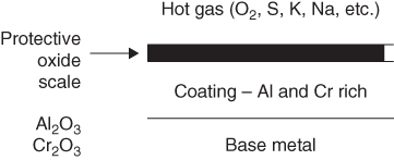
18.2.2 Diffusion Coatings
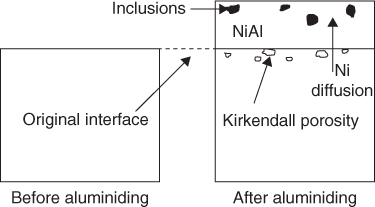
18.2.3 Overlay Coatings
18.2.4 Thermal Barrier Coatings
18.3 Coating Processes
18.3.1 General
18.3.2 Chemical Vapor Deposition
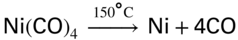
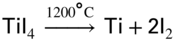
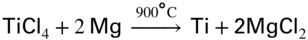

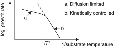
18.3.3 Pack Cementation
Coating type
Source composition
Processing parameters
Pack aluminizing, inward diffusion in Ni2Al3 in nickel alloys
5–20% Al (Al–10Si), 0.5–3% NH4Cl, balance Al2O3 powder
1–4 h at 650–680 °C in air, argon, H2; heat treat 4–6 h at 1095 °C in argon
Pack aluminizing, inward diffusion in NiAl in nickel alloys
44% Al, 56% Cr, NH4Cl, balance Al2O3 powder
5–10 h at 1040 °C in vacuum (argon, H2)
Pack aluminizing, outward diffusion in NiAl in nickel alloys
2–3% Al, 20% Cr, 0.25% NH4HF2, balance Al2O3 powder
25% at 680 °C in argon, 2–5 h
Pack aluminizing of cobalt alloys
8% Al, 22% Cr, 1% NH4F, balance Al2O3 powder
4–20 h at 980–1150 °C in argon
Gas‐phase aluminizing, outward diffusion in NiAl in nickel alloys
10% Co2Al5, 2.5% NaCl, 2.5% AlCl3, balance Al2O3 powder
3 h at 1095 °C in argon
Gas‐phase aluminizing, outward diffusion in NiAl in nickel alloys
30% Al–70% Cr alloy granules, NH4F
4 h at 1150 °C in argon
Pack or gas‐phase chromizing of nickel alloys
15% Cr, 4% Ni, 1% Al, 10.25% NH4Cl, balance Al2O3 powder
3 h at 1040 °C in argon
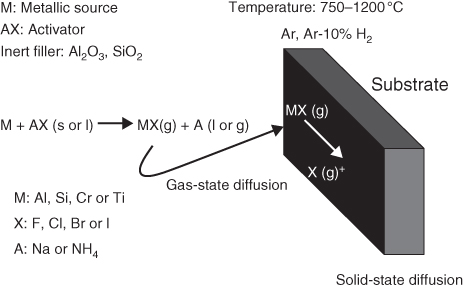
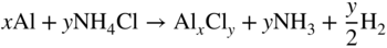


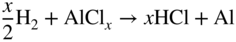
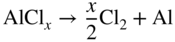

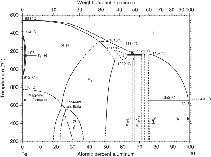
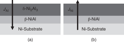
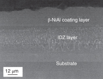
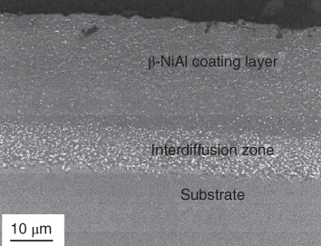
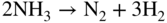
18.3.4 Out‐of‐Pack Cementation
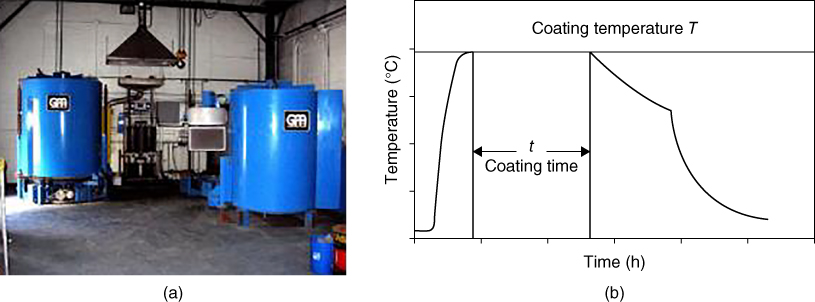
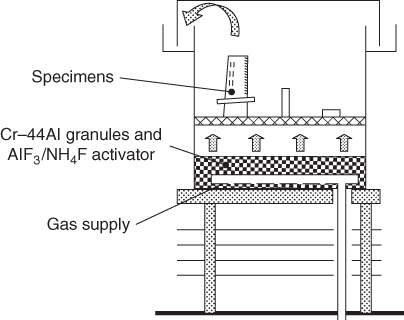
18.3.5 Physical Vapor Deposition
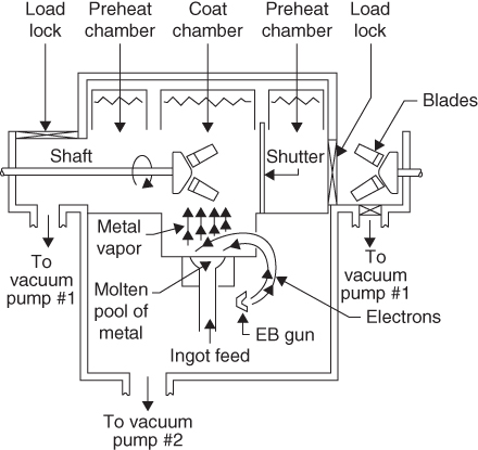
18.3.6 Plasma Spraying
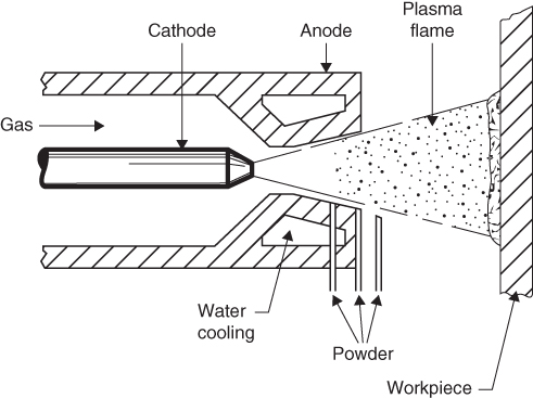
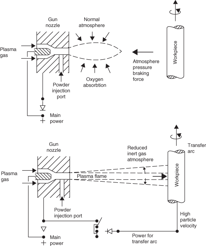
18.3.7 High Velocity Oxygen/Fuel
18.3.8 Other Coating Processes
18.3.8.1 Sputtering Process
18.3.8.2 Ion Plating
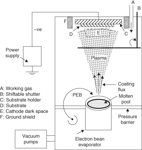
18.3.8.3 Slurry Coating
18.3.8.4 Hot‐Dip Coating
18.3.8.5 Flame Spraying
18.3.8.6 Arc Spraying
18.3.8.7 Clad Surfacing
18.3.8.8 Laser Surface Alloying
Section
Factors in design
Amplification of light
Optical quality; types of windows; means of heat removal; repair and efficiency; cost
Excitation
Power supply; I stage amplifying state auxiliary supply for cooling, pumps, etc.; weight, performance, efficiency; cost
Optical feedback system
Reflector components: mirrors, lenses, coating modulators; windows; mechanical and optical stability
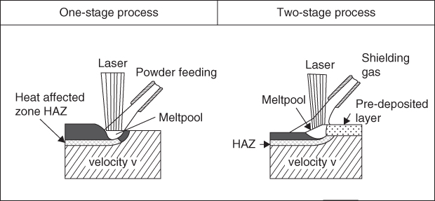
18.3.8.9 Hybrid LPC Plasma Coating
18.3.8.10 Ion Beam‐Assisted Deposition
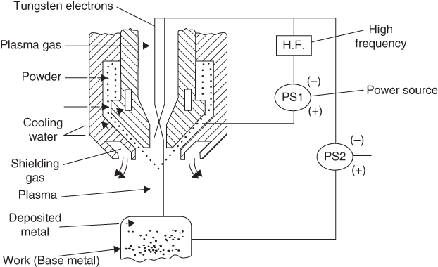
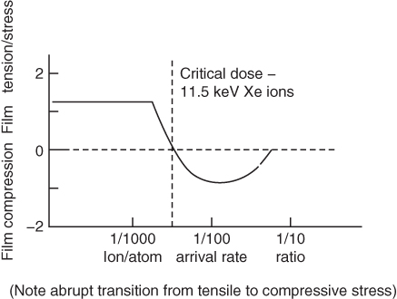
18.3.8.11 Plasma Powder Welding
18.3.8.12 Electroplating
18.4 Coating Degradation
18.4.1 Aluminides
 . Thus, at 600 °C, crystalline alpha Al2O3 grows beneath an amorphous film of gamma Al2O3 by inward diffusion of O2. At 1300–1750 °C, Al2O3 is n‐type up to
  = 10−5 and becomes p‐type at higher oxygen pressures.
18.4.2 Silicides
 . The pattern of growth and retention of SiO2 alone or as an oxide associate is influenced by the manner in which Si is introduced into the system, as an element additive to form an alloy by slurry or CVD methods or by deposition or controlled oxidation to form SiO2 or deposition as ceramics such as SiOxNy or Si3N4 on SiAlON. Although normally very stable, the degradation of SiO2 can occur through cracking, peeling, spallation, or vaporization loss as SiO (Pettit and Goward 1983).
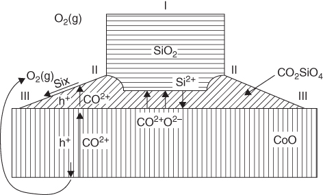
18.4.3 Thermal Barrier Coatings
 . Si and C diffused inward, forming silicides and carbides with the degree of reaction on the ceramic side being similar to that of the substrate below 900 °C and less above 900 °C.
18.5 Summary and Future Trends
18.6 Questions
References
Further Reading
Protective Coatings
18.1
18.2
18.3
18.4
18.5
18.6
18.7
18.8
18.9
18.10
18.11