Rumi Mohammad Ian Verhappen and Ramin Vali Willowglen Systems Inc., Edmonton, Alberta, Canada The daily operation of pipelines has long since been computerized by “SCADA” systems (supervisory control and data acquisition). In its simplest definition, SCADA is a computer network that gathers all the pipeline operational data and brings it into a control room for humans to view and make control actions on. In other words, SCADA can be thought of as the eyes and ears of the people who control the pipelines. SCADA has brought measurable and tangible benefits to the owners and operators of pipeline assets, most notably in terms of safety due to the real-time nature of the SCADA control systems. Because of the proven benefits provided by SCADA to pipeline owners, as well as to the environment and public at large, SCADA systems are considered mission-critical and vital equipment to pipelines. In fact, most jurisdictions around the world have legislated that SCADA systems be installed as a necessary part of all petroleum pipeline systems. The SCADA system consists of several parts including sensors, RTUs/PLCs, computer servers, computer workstations, communication infrastructure, computer networking equipment, and various peripherals (such as a GPS accurate time reference source and many other items). Some equipment is, by necessity, located out at field site locations, while the focal point of the SCADA system is located in one or more pipeline control rooms. Unfortunately, the industry use of the term SCADA is somewhat ambiguous; some use the term to refer only to the software displaying operational data to the pipeline controllers, such as pressures, temperatures, densities, and flow rates, while others using the term also include the sensors and the RTUs that manage them. In this chapter, the term SCADA will be used in reference to both the pipeline control software and the RTUs which sit out in the field and interface to the sensors. SCADA systems can generally be classified as either enterprise level or as HMI systems. HMI SCADA systems are simpler and historically were limited to data collection and presentation, whereas full-fledged enterprise SCADA goes further by including many additional features. Examples of features distinguishing HMI and enterprise-level SCADA are as follows: There can sometimes be confusion with those not familiar with the industry about a similar product called DCS (distributed control system). While very similar in many regards, in that both SCADA and the DCS ultimately collect and display data from sensors in a real-time fashion, the DCS was designed to be used in processing plants where the physical distances between the sensor and computer control system are relatively small. SCADA, on the other hand, can span distances of almost any geographical distance. Large pipelines often exceed 5000 km in length with sensors spread across the entire length, and this is the domain of SCADA systems, where the DCS would not be able to do this. The backbone of the SCADA equipment in the control rooms is the SCADA server computers. These computers communicate with and gather data from the RTUs and PLCs out in the field, maintain the SCADA real-time database, maintain a historical database of past values, an interface to other computer systems, and generally do everything except provide the graphical interface for the human SCADA operators. Best practices for maximizing pipeline integrity require that each SCADA server should contain internal redundancy in the form of dual power supplies, RAID hard drives, dual Ethernet interfaces (connected to dual SCADA LANs), and possibly dual CPUs. To further the concept of redundancy, SCADA servers are delivered in pairs so as to provide a main unit and a hot standby. A good SCADA system will improve upon this by load sharing between the two servers under normal circumstances and reverting to one or the other server if either should fail. SCADA servers may be Windows-based, but UNIX servers are often better suited to industrial applications such as SCADA due to the Windows operating system not having been designed for “real-time” applications. In all but the smallest SCADA systems, the servers are usually delivered without video display, mouse, nor keyboard. Rather they are normally rack-mounted computer hardware providing the background work of the SCADA system. The SCADA system’s user interface is provided through the SCADA workstations. The SCADA workstations exist to present the GUI to the human operators. SCADA workstations are often outfitted with multiple LCD panels with a specific arrangement designed with the physical control room layout in mind. 2 × 3, 1 × 4, and 2 × 2, are all common arrangements. The number of SCADA workstations in each control room should be a function of the pipeline operations and is proportional to the length of the pipeline(s) being controlled (larger companies usually have a network consisting of numerous pipelines, all being controlled from within one control room). Obviously, the minimum is one SCADA workstation, whereas the largest pipeline control rooms contain up to 30 SCADA workstations. Due to the client/server software model, SCADA workstation hardware need not be as hardened as the SCADA servers. Often high-end, off-the-shelf PCs are the best choice for SCADA workstations. Usually, the most important parameter of the SCADA workstation is its graphics ability, which is a function of the video card in the computer. Although there is no need for high fidelity, most SCADA systems produce alarm sounds when a process variable exceeds its nominal range. As such, SCADA workstations should have volume-adjustable audio capability. Currently, the human operator interfaces with the SCADA workstation mostly by use of the mouse, and to a lesser extent the keyboard. However, emerging trends are increasingly augmented with haptic touch screens. Enterprise-level SCADA systems should be able to be implemented in a hierarchical fashion. In a large distributed system, it may be desirable, for example, to have completely independent SCADA systems for each separate region, but a higher-level master SCADA system that receives summary data from each of the lower SCADA systems, thus forming a hierarchy. In fact, this idea of a hierarchy of SCADA systems can consist of more than just two levels; conceptually, it should support three or more levels. For example, SCADA at a municipal level, then provincial level, and finally national level or, alternatively, a pipeline company could have separate SCADA systems for its gas pipelines versus crude pipelines versus its liquid products pipelines and an overall SCADA system on top whose database is the sum of the three lower-level SCADA systems. Depending on the pipeline operator’s needs, it is not always necessary to push the entire database up to the next level of hierarchy. Instead, it should be possible to identify the specific data in the lower-level database that are needed in the higher-level database. Thus by picking and choosing data points, a customized summary of data can be pushed up to the next level of hierarchy. From a pipeline integrity point of view, one benefit that this approach can provide is additional personnel to observe and review operations in real-time. Although not universal in all SCADA systems, best practices in SCADA technology require that there be separate databases for the live runtime data and system configuration. The main reason for this is to allow for system changes to be made and possibly tested out on a development server before being committed to the runtime system. Any SCADA package that does not provide this database separation will have system development being done on the live runtime (production) database. Obviously, the consequences of making an error when editing a database is more severe if those changes are made on the live runtime database. The purpose of the configuration database is to hold the SCADA system parameters. This would be information such as how many RTUs and PLCs there are. How many I/O data points each contains, the computer address of each one, the login user IDs for each human SCADA operator, and generally all system information. The purpose of the live runtime database is to not only use the configuration database as a framework but also to populate it with live data. These two databases are linked through a process called a commit. The best SCADA systems will offer a feedback mechanism between the live runtime database and the configuration database. The meaning of “feedback” in this context is a software mechanism to allow the human SCADA operators to fine-tune certain system parameters on the live runtime database and to have those parameters automatically updated in the offline configuration database. This is a unique and uncommon action as the data flow is normally from the offline configuration database into the live runtime database. Feedback is normally automated for only a small subset of the overall system parameters. In any SCADA system that includes interfacing to more than a single RTU or PL,C it is an important design criterion that the SCADA host should be fault-tolerant. The general design question to keep in mind is: “Is there a single component (software or hardware) that if it fails will prevent SCADA from monitoring and controlling the critical field devices?” Note that a failure of a single RTU will prevent monitoring and control of field devices connected to that RTU, but should not affect the other RTUs, and so usually failure to communicate with a single RTU is not considered critical. However, if there is a single RTU that is considered critical, then that RTU itself should have some fault tolerance built into it, such as a dual communication line, dual processor, or the entire RTU could have a hot standby RTU. The simplest level of SCADA fault tolerance is called “cold standby” and achieved by providing two identical pieces of hardware installed with identical software. If any component fails, then the failed device is manually swapped out with the spare from the cold standby. As this requires a skilled technician on call, the main drawback of this method is the time it takes to fix a problem, and the second drawback is that it requires a regular maintenance step to ensure that the spare devices are working properly and available to be swapped in. The second level of fault tolerance is called “warm standby.” It is similar to the cold standby setup, but the hardware is physically installed and running. If any component fails, it should be set up so that it can be easily swapped out as a whole unit by moving a switch or moving some cables. This significantly shortens the time to fix a problem and lessens the requirements for the technician that initiates the swap. The warm standby still should be checked regularly to make sure it is functional. In this setup, there are often procedures that must be followed after a switch over as the most current configuration might not be installed on the warm standby computer, and recent information such as current process variable setpoints would have to be re-entered. The third level of fault tolerance is called “hot standby.” It is similar to the warm standby setup, except that databases on the two hosts are kept up to date, and it is possible to easily switch control between the two computers. How up to date the hot standby server is varies by the SCADA vendor and can be as little as a fraction of a second to as high as several hours old. For a hot standby setup, the communication links to the RTUs must be designed to be easily switched from one SCADA server to the other. Ethernet connections are fairly easy to switch over; serial connections will require a changeover switch. In this setup, the SCADA host software should be able to automatically initiate a swap if it detects a failure of the active host, or the operator should be able to initiate a swap. The fourth level of fault tolerance is called “function-level fault tolerance.” It is similar to hot standby, except that if a single function fails, for example, a serial port used to talk to an RTU, it is no longer necessary to fail over the entire host computer. In this mode, individual SCADA features can be swapped over from one server to another. This makes an overall SCADA system much more tolerant of small failures and makes it much easier to test standby hardware. This also opens up the possibility for load-sharing when a stand-by would otherwise be unused. In any fault-tolerant system it is very important that the standby hardware be tested on a regular basis. The most reliable means of testing this is by initiating a swap on a regular basis such as once a month. Depending on the hardware, it might be possible to test backup lines automatically. For example, to test backup communications to an RTU, the RTU must be able to support talking with two hosts at the same time. Remember that a backup system that is never tested is very likely to not be working when it is really needed and thus would not provide any fault tolerance. Beyond the above-mentioned software concept of fault tolerance, physical redundancy is one of the most effective tools a pipeline operator can employ to improve pipeline safety and integrity. The basic notion is to provide two pieces of equipment to do a single job: a main and a backup. This concept of the main and backup can be simultaneously employed at three levels. The lowest level of physical redundancy exists within the computer servers themselves. The SCADA servers should be designed with dual power supplies, dual Ethernet interfaces, RAID hard drives, and dual CPUs. Once each SCADA server is built with inherent redundancy, the second step is to provide not just one such server but two such SCADA servers in the control room. In this way, even if one SCADA server is rendered ineffective, a backup SCADA server remains available to take over. This is important because even though many components of each server are provided with a backup, not all components are. For example, the motherboard itself is not redundant. Although it is unlikely that all those components would fail, if they did fail, then the entire SCADA server would be out of commission, and so it makes sense to have a backup. Beyond these is the third and final level of redundancy, which is redundancy of entire control rooms. This is a growing trend in SCADA systems and has legitimate value. History has shown that natural forces can be unpredictable and intense. Threats of tsunami, earthquake, tornado, fire, hurricane, and so on make an entire control room vulnerable. Even if a control room contains two SCADA servers, each of which has redundant components, a tsunami will knock out both servers if it knocks out one, hence the logic behind a second control room situated some distance away, often 50–100 km distance between control rooms. Although the concepts of fault tolerance (described above) and redundancy overlap, there do exist some differences. Clearly, the best approach is to use both redundancy and fault tolerance. Redundancy, as just described, relies on additional software or hardware to be used as backup in the event that the main functionality fails. The primary goal of high availability is to ensure system uptime in the event of a failure. With the continuing adoption of commercial off-the-shelf (COTS) technologies, typically from the business environment into the operations realm, bringing the associated capabilities with it, redundancy can now be economically further enhanced to a high availability arrangement. High availability is a concept that involves the elimination of single points of failure to make sure that if one of the elements, such as a server, fails, the service is still available. This can be achieved through a combination of physical equipment and virtual environments with suitable software known as an orchestrator to manage the different elements contributing to an “always on” environment. One of the roles of the orchestrator is that in the event of a failure, it is rapidly detected and another instance of the function is brought into service. High availability systems operate as a single, unified system that can run the same functions of the primary system they support so that if a service fails, another node can take over immediately to ensure the service remains operational. High availability if executed properly eliminates downtime, including support for updating or adding new capabilities without downtime. Being able to update and maintain the SCADA system without requiring a physical outage of the process, for example, to install a security patch as the name implies, increases the availability and reliability of the system as a whole. The pipeline industry in recent years has formally acknowledged the value of human factor design in SCADA systems—shown through recent U.S. regulations such as the amendments made to 49 CFR Parts 192 and 195 regarding Control Room Management (CRM) and the Pipeline Inspection, Protection, Enforcement, and Safety Act (PIPES) requiring a human factor plan to CRM. The value of assuring that central control systems are designed to provide early detection of abnormal situations, in a manner which does not provide a stressful environment for the human operator while also recognizing the need of fatigue management, has been recognized in the refining and process industries for many years. There is a wealth of knowledge from the ISA, NPRA, and other organizations that can be applied and adapted to the pipeline industry. The key elements of an effective human factors plan for control room management (see references) require the design of the SCADA system to equip the operator with the information needed to properly operate the pipeline safely and reliably. The manner appropriate for delivering this information needs to consider the ways humans process information, at all times of the day, after many hours on shift, as well as how to capture and transfer this information through to the next shift. After the National Transportation Safety Board intensively investigated the root cause of past pipeline incidents, they identified five areas for improvement: graphic displays, alarm management, operator training, fatigue management, and leak detection. Graphic displays and fatigue management have common elements, but in addition, the physical control room design has a significant role to play in fatigue management via elements such as room lighting, monitor placement, and separation of areas of responsibility. As computer graphic displays are the primary method for control room operators to visualize the big picture of the state of their entire pipeline operations, this is often considered the top opportunity for improvement when first implementing a “Human Factors Approach.” The recommended practice for pipeline SCADA displays API RP 1165 is expected to be followed, and expert practitioners have applied the research from industrial psychologists to achieve significant improvements in operator comprehension and speed of response. Some of the main considerations when developing graphics optimized for human factors are to “selectively use reserved colors” against a gray-scale background versus the traditional “black background utilizing the full color spectrum.” Also, providing a confirmation identification element that can help color-insensitive personnel confirm their understanding of the situation is key to allowing a clear diagnosis of the issues by the general control room population. These advancements to graphic display designs have reliably shown improvements to comprehension and response time of over 50% and in addition have shown that the learning curve is significantly reduced for inexperienced personnel who tend to be the most vulnerable during times of emergency. Despite the recognized value of using a “human factors” gray-scale approach, it is often difficult for existing operators to be enthusiastic about losing their black background graphics. As with any change, there is an adjustment time, additional work, and re-training. However, operators who move on to a new area of responsibility do appreciate the human factor gray-scale approach and are able to master the new area earlier than ever before. Of course, taking a human factor approach to pipeline design, operations, and maintenance has applications and benefits beyond the control room—as is shown in the human factors chapter (Chapter 15) in this book. Alarms notify human operators about abnormal situations so that they can respond in a timely and effective manner to resolve problems before they escalate. Studies have shown that the ability of operators to react to alarms depends largely on how well alarms are rationalized and managed. In the early days of SCADA, alarms had to be hard-wired to physical constructs such as flashing lights and sirens. These physical limitations forced designers to be very selective about what to alarm upon. By comparison, modern software-based alarms are often considered free. This creates a common mindset where anything that can be alarmed upon is configured to do so. The result is a SCADA control room with a constant overload of alarms, often unnecessary or unimportant, which operators are expected to filter through when searching for “real” alarms with serious consequences. Efficient alarm management begins with proper alarm rationalization. Every alarm configured in the system must be considered carefully by a team of experts with operational domain knowledge. Consequences with regards to safety, finance, and the environment must be factored in. The goal is to create as few alarms as possible, while accounting for all serious consequences. The approved alarms and procedures for responding to each alarm should be captured in a Master Alarm Database (MADb), which is then periodically reviewed by the team. The MADb serves as the foundation for configuring alarms within the SCADA system. Alarms must capture an operator’s attention, and depending on the severity of the alarm, this is done using a combination of graphic effects such as flashing colors and repeated sounds. It should be easy for the operator to distinguish the process variable in alarm from other process variables which are not in alarm. For example, a red flashing border stands out against an otherwise gray screen. Operators should then examine and acknowledge the alarm. Information which can help the operator react to the alarm should be easily accessible from the context of the alarm. A summary list of recent alarms helps operators identify when an alarm occurred, the nature of the alarm, its severity and scope, whether it is still in alarm, and whether an operator has acknowledged it. A searchable list of historical alarms helps both operators and analysts to track alarms over long periods of time to detect important patterns. These lists can be filtered and sorted. Sometimes, alarms need to be suppressed. Operators can suppress alarms for a short period, for example, when a sensor is temporarily malfunctioning. Alarms can be configured to be suppressed for long periods of time, for example, when a point is still being commissioned. Dynamic logic can also suppress alarms, for example, suppressing a low-pressure alarm for a pipe when the corresponding valve is closed. Long-term operational use reveals badly configured alarms. There is an arsenal of techniques to correct these configuration issues, based on analysis of recurring trends. Analog alarms which constantly chatter between low and high values can apply deadbands to mute the noise. Digital alarms that quickly switch states multiple times can apply on-delays and off-delays to stabilize the state transitions. Incidental alarms for a device power outage can be presented as a single group of alarms. Analytical tools can hone in the most frequent offenders, which when dealt with can reduce unnecessary alarms by large percentages. As established earlier, fewer alarms make alarms more manageable for operators in real-time environments. In any SCADA system, there will be situations that arise that the management will want to have reviewed to find out what exactly happened and whether the operator had sufficient information available to properly handle the situation. A SCADA system should provide tools to make it possible to review these situations. Some SCADA systems include audio recorders on all phone lines and radio channels for this kind of review. It is also possible to record the operator screens to verify whether the operator went to the correct screens to diagnose a problem. The disk storage requirements for this are quite high, so the number of hours of storage will have to be limited. There are also potential personnel issues with this level of monitoring, which should be carefully reviewed. A SCADA system should also provide tools to analyze the precise order that things occurred in, preferably to the millisecond. The activities that need to be monitored are as follows: when field devices such as valves or circuit breakers changed status, when operator commands were sent out, and when operators acknowledged alarms. Additional information such as updates for analog values from the field can also be very useful in analyzing an incident to check if an analog changed before a command or in response to a command. A simple tool might look something like a text log of each change, but that is difficult and time-consuming to review, but does contain very precise information. A better system will replay the incident using the same screens that are available to the operator showing the current state of the system. The best system will include both the text and GUI interface and allow for slow replay and pauses. In summary, it is important that an incident that occurred be able to be recorded and made available for review in an offline system. One of the many aspects critical to the proper use of a SCADA system is the integrity and quality of the data displayed to the human operator in the control room. There are several conditions that may adversely affect the data being displayed, and it is important that the operator be aware of what these conditions might be and when they are occurring. Because SCADA systems are computerized and are thus aware of the context in which the data were gathered, they can also infer the quality of the data and advise the operator if the data are questionable. For example, if the communication link between the SCADA server computers and an RTU is broken for whatever reason, most SCADA systems can inform the human operator that the data being displayed are stale. It is important for the operator to know that the data currently displayed for RTU in question have lost their “real-time” nature. While the list of possible data quality conditions is quite long, Table 7.1 shows some typical data quality conditions: Table 7.1 Data Quality Terms, Indicators, and Meanings SCADA systems use a visual flag to indicate when any of the data quality conditions are present. In order to not dominate screen space, the flag is usually represented as a single letter associated with the data point in question. The single letters shown in the table are examples of those which could be shown in a SCADA display screen. Once a pop-up is rendered, the SCADA system should provide a more descriptive indication of the data quality condition if such is present as shown in the above table. More sophisticated SCADA systems maintain a hierarchy of data quality conditions and can arbitrate which to display if simultaneous conditions exist. Also, better SCADA systems will be able to propagate data quality conditions present with calculation inputs through to the output results of those calculations. Data quality should also be maintained in the historical database so that this meta-data are preserved when historical values are recalled. The 49 CFR Parts 192 and 195 regarding control room management (CRM) provides a clear definition on the needs for Shift Handover. “Pipeline Operators must also establish a means for recording shift changes and other situations in which responsibility for pipeline operations is handed over from one controller to another. The procedures must include the content of information to be exchanged during the turnover.” The intent is to capture important information that has been provided or has occurred during the shift—and which the next or future shifts should be aware of in order to responsibly operate the pipeline. Operators have long kept physical handwritten logbooks; however, electronic logbooks and shift handover software tools are now the norm. These electronic tools can range from being an integrated part of the SCADA system to separate stand-alone software. There are advantages to both approaches. With the advance of these software tools, control room operators now have much better access to fuller (and now searchable) information of what has happened in previous shifts. Information access can also be role-based at the operator, shift supervisor, manager, and other levels. Systems which allow operators to select entries based on drop-down selections (thus require less typing) tend to obtain fuller information; also, the information is more standardized and sortable. Key information captured in operator logbook and shift handover tools can include the following: With this information now more easily available, currently, operators are better equipped to avoid information transfer loss during shift handover, which has in the past been a significant contributor to pipeline incidents and/or operation inefficiencies. There are many aspects to consider when it comes to SCADA systems and how they relate to pipeline integrity. One often forgotten aspect is the human element and the need for training. All too often when a SCADA system is commissioned, the pipeline operating staff receive a set of training courses on the use of the SCADA system, but what about eventual staff turnover? When new SCADA staff are hired, who will teach them the system and with what credentials? Once a new SCADA system has been delivered, it rarely happens that the pipeline owner hires the SCADA vendor to return to the facility to teach new staff members. Indeed, training via experienced workers offers several benefits but can sometimes also have some disadvantages as experienced workers are not necessarily skilled teachers. A full- featured SCADA system can compensate, in part, by providing training tools. The ultimate in training aids is a full hydraulic model built onto a SCADA simulation workstation that is identical to a real SCADA workstation. Such a facility would not only look but also feel like the actual SCADA system, with accurate hydraulic calculated results for the SCADA operator’s actions. For many companies, however, such a hydraulic model is prohibitively expensive, as these packages often cost more than the entire SCADA system itself. A reasonable compromise is a training tool that simulates the look of the SCADA system but is not connected to a hydraulic model (i.e., a tool that looks like but does not feel like the real system). Lacking the hydraulic model means the trainee cannot take actions and observe the results of their decisions, but such a training tool can provide a different training benefit: There is at least one SCADA system available that has a SCADA training simulator that functions by replaying previously recorded time periods of SCADA activity. It allows a trainer to insert pauses and questions for the trainee to respond to but is limited in that whatever decision a human trainee makes, when he continues the replay, there is only one decision tree that can be followed. Regardless of this, such a tool would give the trainee hands-on time at the controls of an identical SCADA system and could be given prerecorded scenarios to follow. The scenarios could be both best practices in terms of how to do regular duties as well as the possibility to replay accidents or incidents. With training tools, new employees can be trained more quickly and more effectively than without and also affords the opportunity to have each human SCADA operator certified for a variety of procedures and emergency response. All these ideas will improve the daily operation of the pipeline, avoid costly accidents, and thus contribute toward greater pipeline integrity. Since SCADA is fundamental to pipeline operations, it follows that SCADA security is fundamental to pipeline security and integrity. SCADA, as a mission-critical element to pipeline operations, is vulnerable to a variety of threats and, thus, needs protection. The first type of SCADA protection to discuss is physical security. The SCADA infrastructure (servers, workstations, communication equipment, and RTUs) needs to be physically protected by access control systems. It should not be possible for the general public to gain access to these assets. Access control for an RTU is often achieved by putting the RTU in a weather-protected enclosure and then locking the enclosure. Sometimes, the enclosure also has a perimeter fence around it to add an additional barrier. This can be augmented with a prosecution quality CCTV system. As for the SCADA servers and workstations, this equipment is usually located in an office building, and thus it is quite easy to have this equipment behind locked doors. To increase access control to the SCADA control room, it is also possible to add further access controls to the individual equipment room(s). Such facilities usually have a separate environmentally controlled server room to host the SCADA and other computer servers. Beyond physical access control, the SCADA equipment needs to be protected from the environment to continue to operate properly: SCADA servers should be temperature-controlled; RTUs should be protected from the ambient environment (dust, moisture, hazardous gases, etc.), and the entire control room should be located out of harm’s way and away from natural disaster zones. In addition to physical security in the form of access control and environmental protection, because a SCADA system relies on computers and networks to communicate between different elements that constitute a SCADA system, it also needs to be hardened against cyberthreats. This means that the SCADA servers and workstations should prevent unauthorized programmatic access by locking down all I/O ports (USB ports, CD drives, Ethernet ports, serial ports, etc.). Connections between SCADA computers should also be made via secure channels such as SSL. New cybersecurity regulations have been promulgated and continue to evolve in response to the growing threat arising as a direct result of the increased connectivity between business and operation systems. Consequently, cybersecurity is a mandatory requirement for any network-connected device, which, with the predominant use of microprocessor-based controllers and sensors means for all intents and purposes every device connected to the SCADA environment. Traditional SCADA systems were largely based on proprietary protocols and private networks with limited connectivity to any external systems. However, starting in the 1990s, commercial off-the-shelf (COTS) technology such as Windows™-based interfaces, servers, and other business system hardware has made its way into the OT/SCADA space. The adoption of common infrastructure also made it easier to connect to the IT/business world, which when combined with the benefits of machine-to-machine data transfer has resulted in increasing interconnectedness of all systems. This commonality and connectedness result in similar vulnerabilities but with different outcomes. Figure 7.1 shows representative elements and cybersecurity priorities of the office environment on the left and the SCADA environment on the right. The most significant difference between the OT and IT environment is that in the OT environment, unlike the business realm where an individual computer can be isolated from the network, it is not possible to shut down or isolate a compromised OT controller because doing so will in most cases lead to a production outage and in others an unsafe failure condition, and hence is to be avoided if possible. Figure 7.1 Cybersecurity hierarchy office versus SCADA. (Willowglen systems.) In addition to using different hardware, which is typically ruggedized for the environment in which it will be used, the roles of the elements in the IT and OT space are also different. The Purdue Enterprise Reference Architecture (PERA) or Purdue model was developed at Purdue University in the 1990s as a functional reference model to describe what each layer between the process and all other systems through to the enterprise. (external supply chains were not an issue then.) The PERA model (Figure 7.2) from the ISA-112 SCADA standard represents the separation between functions in a top–bottom/north–south hierarchy. As can be seen by the diagram, because of the close relationship between the function and the equipment, particularly at the lower levels of the model, it is quite easy to confuse functions with hardware used to deliver the function. Because PERA is a functional model, elements such as firewalls that are required and used to separate and isolate different zones are not shown. The control layer contains specialized hardware and software, as described in this chapter, to provide real-time data collection and response through the use of field devices (sensors and actuators), local regulatory control functions for rapid response, through to the operator interface and higher-level optimization applications within the SCADA servers normally located in the central control facilities. When possible, the link between the SCADA servers and RTUs should be secured. Applying encryption to the data link is one way to do this, but this is not always practical when different vendors have supplied the SCADA system and the RTU. When a single vendor has supplied the equipment at both ends of the communication line, it becomes easier to add an encryption algorithm to the communication channel. This will prevent eavesdroppers from decoding the data and commands taking place on the link, especially when wireless communications are used (as is the case with microwave communications). Taking this idea further, when one vendor supplies both RTU and SCADA, a software authentication method can be added which will prevent unauthorized users from injecting commands to control and possibly damage pipeline assets. Because the data contained in a SCADA system are useful to other departments of a pipeline company, it is very common for there to be a connection between the SCADA system and other business systems. Direct connections between the office and control environments should be avoided. The use of a demilitarized zone (DMZ) as a buffer between the SCADA and business networks will mitigate the possibility of a virus or other cyberthreats from reaching the mission-critical SCADA network. The DMZ, also known as the process information network, is the “buffer” between the information technology (IT) business systems and the operations technology (OT) automation and control (SCADA) systems. The purpose of a DMZ is to ensure no direct connections from the IT and other external networks to the OT systems. The DMZ connections are configured so that approved devices on the IT and OT networks can write to and request information from the DMZ, but the two networks cannot transfer data between each other directly. DMZs also provide controlled access to services used by external personnel to access the control system network and equipment. Figure 7.2 SCADA reference architecture. (ISA-112/https://www.isa.org/getmedia/8883748c-12bc-42e7-8785-b0fbf481e83b/ISA112_SCADA-Systems_SCADA-model-architecture_rev2022-01-26.pdf/last accessed Feb 15, 2024.) Firewalls are a critical security component to manage traffic flow across different parts of the network. It works like a traffic controller, monitoring and filtering traffic that wants to gain access to your operating system and then blocking unsolicited and unwanted incoming network traffic. The most basic form of firewall is a packet-filtering firewall that similar to “do not call lists on your phone” blocks network traffic based on the IP protocol, an IP address, and a port number. A stateful multilayer inspection firewall is also able to filter traffic based on state, port, and protocol, along with administrator-defined rules and context. Proper implementation of defense in depth layered protection and Zero Trust networks, which are becoming mandatory in regulations, require the use of a next-generation firewall that goes beyond standard packet-filtering to inspect a packet in its entirety. That means inspecting not just the packet header but also a packet’s contents and source. NGFWs are able to block more sophisticated and evolving security threats like advanced malware, while also being able to provide granularity to individual device-level monitoring/protection. With the increased focus on the cybersecurity, industry and regulators have responded with a number of standards and requirements. The following list identifies a number of such sources from the broadest application down to pipeline-specific documents: Cybersecurity and SCADA professionals strive to maintain a secure and available environment, and a single bad change is all it takes to open the door to a bad actor and hence a potential vulnerability. Everything that happens (good or bad) in the computing environment starts with a change: a file, configuration setting, or device is altered, deleted, added to, or even just read by a user or service. Unauthorized, unexpected, and unwanted changes to critical files, systems, and devices can quickly compromise system integrity. This is why a solid management of change process is required for the SCADA system to maintain the required level of availability. Fortunately, an organization’s existing management of change processes can typically incorporate the additional control system integrity requirements. Every user in the SCADA system is assigned a set of permissions and areas of responsibility (AORs). Permissions define what actions a SCADA operator is allowed to do or not to do. AORs define the parts of the system where the SCADA operator can perform their list of allowable actions. Permissions can be used to grant or restrict actions from simply being able to browse information to restoring databases to earlier versions or setting the system time. Any combination of permissions can be granted to a user. Typically, permissions are grouped by user roles. A visitor or observer of the system is limited to browse permissions only, with the ability to read information from the system, but has no ability to change any information or send any commands. An operator typically has permission to send commands to field devices and acknowledge alarms. A configuration engineer has permission to edit the database. At the highest level, a system administrator has permission to restore database and manage user accounts and do everything. A user can choose to temporarily disable some permissions. An operator who normally has the ability to acknowledge all alarms at once may choose to disable that ability under normal circumstances. They can also choose to enable it again if needed. Areas of responsibility (AORs) divide users into different areas of the system. Areas that do not belong to a SCADA user are filtered out. One operator can still inspect other areas of the system but is prevented from taking any action in areas they are not authorized for. A single user may have multiple AORs. A single AOR may have multiple users assigned to it. A single database point typically exists in a single AOR. A point not assigned to an AOR is considered global and therefore accessible for all users. A user can choose to temporarily disable some AORs. A system administrator is authorized to access all AORs and may choose to disable AORs that are currently manned by other operators. This is applicable, for example, if one of the other operators leaves early; the first operator can choose to re-enable that AOR. Traditional cybersecurity practices are designed to protect up and down (north–south) between different networks or layers. However, experience has shown that this does not provide sufficient protection from accidental or intentional internal threats, so current cybersecurity practices are dependent on defense in depth, which also requires separation with a network layer. This internal separation, similar to the VLAN concept, is often referred to as a zone and conduit model, with zones typically based on equipment providing a certain function. However, with the increasing complexity of systems plus the requirements of IIoT devices and cloud-based data outside the domains controlled by an organization, a new form of protection able to resolve to independent services is required. This new form of protection is known as zero trust and is being mandated in a number of regulations. Zero trust is, as the name implies, based on the principle of “trust none–verify all,” which requires NGFWs as described above to implement the needed resolution and analysis of potential threats. There is a wide range of standards for SCADA available as of this writing. Most standards focus on a specific area of SCADA such as alarm management, security, or graphic display. Some standards apply to process industries in general, while others are for individual industries such as oil and gas, pipeline, electrical, and transportation. Some are created by formal regulatory bodies which require organizations to adhere strictly to requirements, while others are from established consortiums that recommend guidelines that may form the basis of future regulatory requirements. Standards often borrow from each other, building upon legacy documents to add variations or new requirements. Core themes from various standards include the following: Essential standards for the pipeline industry include the following: While some standards or requirements are very specific and detailed, others tend to leave room for interpretation. Thus, different SCADA providers may provide different solutions to meet selected standards. In general, standard compliance by organizations is achieved by best practices, which a SCADA system can help achieve. Understanding of human factors and industry workflows is essential to interpreting and implanting standards. While at its most basic definition, a SCADA system simply presents operational data to humans in a control room for them to take action, the reality is that after years of R&D and continued refinement, SCADA systems now offer much more than this basic functionality. One way that SCADA systems offer more is by adding optional software application modules. While there may be many such applications to choose from, three important ones for pipeline integrity are as follows: leak detection, batch tracking, and dynamic line coloring. Obviously, it is necessary for pipeline operators to know if they have a leak in their system. Several reputable companies offer software modules that can do this, and some SCADA systems have this ability built-in. Either way, these software application modules must interface to SCADA due to use of the real-time data for constantly monitoring for leaks. By using live operational data from the SCADA system, these modules run algorithms to compute if there is any product missing from their pipeline system. If a leak is detected, the leak detection module can push data back into the SCADA system to alert the human operator. There remains some debate as to which is the better approach: to build the leak detection module directly into the SCADA system or have it as a separate add-on module supplied by a third-party vendor. The advantage of having it built in is a tightly integrated solution that should be seamless between SCADA and leak detection. However, the advantage of a third-party leak detection package is technical ability. It does stand to reason that the core strength of a SCADA company is its SCADA software and to a lesser degree the ability of its leak detection add-on, whereas a dedicated leak detection company will focus its efforts primarily on its leak detection software. So long as the SCADA system and third-party leak detection package can successfully exchange data, something more easily accomplished these days by OPC, it should be a powerful combination. Batch tracking is an optional add-on module that is used for liquid product pipelines (as opposed to gas or crude oil pipelines). In total, there are maybe 100 different refined products that can be output from a refinery (e.g., gasoline, kerosene, jetA, jet B, and diesel). These different products follow one another in the same pipeline, and thus is it necessary for the pipeline operator to know which batch is at which location in the pipeline, both for injecting additional products and for extracting products at delivery points. Like the leak detection module example above, batch tracking can be built into the SCADA system or provided by a third-party vendor. Proper operation of the pipeline is, of course, vital to pipeline integrity, and any tools that can assist the proper operation or avoid improper operation are important to operational integrity. One feature that quality SCADA systems exhibit is “dynamic pipeline highlight.” This is a feature that can visually indicate to the human SCADA operator if any given section of the pipeline is flowing or not flowing. In other words, the graphics on the screen that show the pipeline can use color or other highlighting to indicate if any given section of the pipe is safe or not, and it can do this in real-time based on upstream valves being open or closed, etc. Surprisingly, not all SCADA systems have this ability, yet it can be easily understood that this information is valuable for the daily operation of the pipeline and thus for ensuring its integrity. Artificial intelligence (AI) and machine learning (ML) have successfully saved costs, increased revenue, and achieved other performance metrics for well-known pipeline companies in Canada, the United States, and around the world. This methodology has proved effective because pipeline systems are often too complex for their behavior to be accurately predicted with first-principle calculation or simulation software. The AI ML approach uses historical data from the SCADA system to create a predictive model that can quickly and accurately estimate system flow rates. An AI ML solution can be implemented to provide control room operators recommendations in real time so that pipelines can be confidently operated in an optimized manner. This overview is intended to give you an idea of the types of optimization benefits that can be achieved with this technology. It will not address the areas of predictive failure or predictive maintenance, nor is it intended to guide you in completing your own project. Benefits can be realized for oil or gas pipelines. An optimized flow model for pipeline operators can be developed using AI ML methodologies. The solution includes an ML predictive model that can determine the pipeline throughput flow rate based on any combination of set points across the system. The solution also contains an AI optimization engine that makes recommendations to the operator so that they can execute system set points to achieve the required outcome in the most “efficient” manner. The solution is implemented with a mechanism to retrieve real-time data from the SCADA environment used to generate the predictions and recommendations. Before beginning, it is best to determine the objectives to be achieved in optimization. The optimization engine can optimize for a single objective or a combination of objectives. You may wish to simply maximize the throughput and not take into consideration the cost of power or DRA (drag reducing agent). The system may be optimized to achieve the lowest cost of operation while maintaining the desired flow rate. This could be achieved by considering the cost and usage of both electricity and DRA. Other objectives or constraints for optimization could include throughput, emissions, pressure volatility, batch scheduling, startup routines, or storage utilization. A new predictive model is built offline by extracting data from the Historian. A typical extraction is 800–1000 data points for the last 12 months of “normal” system operational data required to account for seasonality in the data, although if more data are available, this could improve model performance. To design the models, minute-by-minute time-series data are required where available. The extracted data set will need to be analyzed for completeness and consistency by a data analyst who is familiar with pipeline operational data. There are often data gaps, errors with measurement units, and other issues that are best resolved prior to initiation of the creation of the model. This is necessary to structure the time-series operational data for statistical analysis and modeling. This includes data cleaning, noise removal, elimination of anomalous operating conditions, and outlier detection. The data set is processed with a series of calculations and algorithms through an ML data pipeline. This is the supervised ML approach in which human interaction is a critical component. Domain expertise is also important and in this case, an understanding of pipeline hydraulics and the associated physics. This allows for the creation of a hybrid model that combines the physics with the data analytics of ML. All of this effort greatly increases the accuracy of the model’s predictions. Once the model is creating valid predictions, it can be used to calculate the theoretical improvements that would be realized when it is in service. You can compare pressure cycling patterns seen historically with the patterns that would be seen by using the new model. You can do this with DRA use, or throughput, or power costs. The comparisons should enable you to create a value assessment that specifies tangible expected outcomes. If the potential improvements are not compelling enough, you can choose to not proceed with the implementation of the solution. For the predictive model to make recommendations in real-time, the solution will need live access to the following data from the SCADA system: The decision support module would be installed on a server and can be virtualized on an existing server cluster. The complete production solution will require multiple servers for high availability fault tolerance and does not necessarily require access to external networks. The server and workstation will need to be connected to the production network. Cybersecurity of the system should be compliant with standards such as ISA 62443 and API 1164. The predictions that the model generates will get slightly less accurate over time due to expected operational “drift” in the system. It is important to monitor accuracy systematically and plan for regular model retuning. Retuning is a minor exercise and may be necessary once a year or more based on pipeline system size and complexity. If there is fundamental change to your pipeline system like line diameter or a new pump (compressor), a model rebuild will be necessary. This is an exercise that is more work than a retuning, but not as much as the initial model creation. The optimization engine is where you capture the business rules and constraints for the system. This includes cost of power, DRA, equipment operating parameters, and the like. The system can also be given temporary system constraints by the operator to address short-term issues. An example would be if a pump is not available or operating in a limited capacity or if there is a pig in the line. The predictive model honors all the constraints to ensure the recommendations are given within acceptable operational parameters. In the event of hard operational setbacks, like maintenance or pump failure, the program can automatically reconfigure to the most profitable recommendation with the available pumping resources. The application will implement an optimization engine and an AI ML digital twin based on historical data. Energy consumption will be determined directly based on the pump electricity consumption or indirectly based on fuel consumption. The optimal combination of pump stations required to deliver the operating flow rate will be achieved by setting the suction and discharge pressure setpoints for the local controllers at the pump stations. The application will implement the throughput amplification mode of the optimization engine. The optimization engine will access the desired flow keyed-in by the user with the digital twin considering the physical and safety constraints of the system. The amplification mode will automatically calculate the optimal combination of suction and discharge pressure setpoints for the pump stations for the realizable desired flow rates. Furthermore, this mode allows users to select or unselect specific pumps from the available line configuration. This allows the optimization engine to provide optimal recommendations with the available pumping resources in the event of equipment failure or maintenance. This helps achieve the maximum throughput capacity under a wide range of circumstances. When the solution is tested and operational, it is a good idea to have it run in the control center for a few weeks without the operators using its recommendations. This is a chance to compare the running of the pipeline by the operators to the recommendations of the AI ML solution. With this information, you will be able to confirm the value the solution will be able to deliver. At this point, the solution should be ready to roll out for use by the operators. The ultimate goal of the solution is to support the control center operators in running the system in an optimized fashion. It also allows new operators to become proficient much faster. The AI ML solution supports the decisions of the operators. There are three typical ways in which the solution can be implemented into the control room environment after it has been proven as reliable and effective. The solution can be installed in a stand-alone fashion in the control room. It pulls live data from the SCADA system for real-time set point recommendations, but it is not integrated into the SCADA UI. It can run on a separate laptop computer. This is a good first step as it allows the operators to gain confidence in the recommendations being provided by the model. The downside is that the setpoints will still need to be manually input into the SCADA system. After the operators have gained comfort with the standalone system, they may become frustrated with manually transposing the recommended setpoints into the SCADA, especially on systems where the adjustments are frequent. The AI ML solution can be integrated with the SCADA UI (user interface) with a fairly straightforward configuration project. The SCADA can then be fed the recommendations from the model and display them for the operator. In the semi-autonomous mode, the system makes recommended changes to the setpoints when appropriate, and the operator needs to explicitly accept the recommendations and have the setpoints seamlessly implemented. In the autonomous mode, the system makes recommended changes to the setpoints by sending an alert or notification to the operator that a change is forthcoming. The operator does not have to explicitly accept, but they can stop the changes if they feel that is appropriate. A project was completed for a 450-km (280 mile)-long crude oil pipeline with seven pump stations. The solution provides the optimal recommendation for the ideal combination of discharge pressure and DRA (drag reducing agent) setpoints to maintain the flow rate at the lowest possible cost of power and DRA. Furthermore, the effectiveness of different classes of DRA derived through the advanced statistical analysis was directly configured into the optimization engine to identify the optimal region of operation under different operating conditions. Monthly power consumption improvements ranged between 17 and 34% in the first year of use. DRA costs were also lowered considerably, but no hard numbers have yet been calculated. Like any computer-based structure, SCADA requires connections between the different elements or nodes (controller, workstation, server, gateway, etc.) of the system. While the RTUs gather data from a variety of instrumentation, these data must be communicated up to the SCADA server computers, and a variety of communication media can be employed to effect this communication. The selection of communication media is influenced by factors such as purchase and install price, operating price, reliability, availability, bandwidth, and of course geographical considerations. Another aspect is suitability for data transmission via serial or Ethernet methods. Because of the widely distributed nature of SCADA systems, as described below, they use a broad range of media to distribute messages between nodes. Copper media, typically referenced by CAT n (category n = 3–7), is used for Ethernet communications. Because cable lengths are normally limited to roughly 100 m, Ethernet cables are predominantly used in settings where the necessary infrastructure is in place, distances are relatively short, and the environment is controlled. That is not to suggest the RTUs must be within 100 m of the SCADA servers; rather repeaters or other active equipment are used when necessary to bring the data into an alternate transmission method for longer distances and at rates of up to 1000 Mbps. Cat 5 or Cat 6/Cat6e cables and the equipment needed to support them are ubiquitous and relatively inexpensive. Cat5 and higher cable media usually have a very low bit error rate and thus very high communication integrity. IEEE which develop the Ethernet cable specifications have for low power applications defined Power over Ethernet (PoE) capabilities supporting transmission of data and power over different wire pairs within the same cable. Driven by the need to reduce weight and resources, single pair Ethernet (SPE) for the industrial sector supporting longer distances at lower data rates has also become available. A leased line is a pair of copper wires, often referred to as Plain Old Telephone Service (POTS), like a residential landline, which is rented from a telecommunications provider to carry serial data. Modems must be installed at both ends of the leased line to use a leased line. Leased line bandwidth offers lower bandwidth, than Ethernet, but is still fit for transmitting RTU data. Because the telco provider is responsible for the infrastructure, communications integrity is usually very good with leased lines. This communications option is very similar to leased line media using serial communications over dial-up lines, which differ from leased lines, in that they are not always on, but connect when they have data to transmit. Dial-up lines provide serial data transmission only at lower bandwidth, but the data rates are still suitable for most SCADA applications. Two of the greatest advantages of dial-up communications are the low installation price and low ongoing monthly fees. Dial-up communications also enjoy comparatively low bit error rates, making dial-up a fairly robust choice to transmit SCADA data. Fiber optic communications offer the highest data rates of any existing communications media, rates that are far greater than needed for passing field data up to the SCADA control room, and are therefore used for the backhaul/wide area network part of the system. The optical fiber is also an extremely reliable media for data transmission. The reason that fiber optic is often not used is the relatively high price of installing the fiber versus other options. Long distances—especially through undeveloped areas—are prohibitively expensive, but if there is an existing fiber that can be used, then this option may be a good choice. Fiber is also a good choice for electric power companies as it avoids the liability associated with copper spanning distances where a high-voltage ground fault can vaporize the buried cable. Since optical fibers are made of glass and thus not electrically conductive, they are an excellent choice in areas that can experience ground faults. Many companies are now taking the opportunity associated with installing new transmission lines or pipelines to use the same right-of-way and incorporate fiber optic cable infrastructure at the same time. This is good news for new pipeline installations because they can use a small portion of this new fiber as the basis for a reliable SCADA network infrastructure. The widely dispersed and lower data rate requirements of SCADA make radio communications a widely used option for communications between the field RTU and a central location MTU (master terminal unit), which in many cases these days is a server-based device. Large SCADA systems could have more than one MTU. The biggest constraint to radio-based communications is that they are limited to line-of-sight, which explains why they often have high (and expensive) towers. Another radio communications “rule of thumb” is that data transmission capability (i.e., how many bytes of data can be carried) is proportional to frequency, but distance is inversely proportional to frequency. This means a radio operating at 2.4 GHz will be able to carry much more data than a 900-MHz radio but only be able to transmit that information roughly one-third the distance. Radios are also susceptible to interference from ambient conditions, but generally because of the line-of-sight constraint are quite reliable, while having the advantage that they can be entirely within the owner/operator’s control. Radio systems are broadly classified into license-free (like Wi-Fi) or licensed, which as the name implies requires granting of spectra by the country’s radio frequency management authority (FCC in the USA, Industry Canada, Ofcom in the UK, etc.). Global responsibility for spectrum management is under the responsibility of the ITU (International Telecommunications Union). License-free spectra, often called ISM (Industry, Scientific, and Medical) bands are the ones commonly found in commercial products such as Wi-Fi and Bluetooth-connected devices—including many IoT-enabled items. The two frequencies 2.4 and 5.8 GHz are the most commonly used license-free spectra (Wi-Fi, Bluetooth, etc.) globally because they are the same around the world while also offering a good compromise between distance and bandwidth for the majority of on-premise applications. A 2.4 GHz system’s range capabilities are typically 150 ft (35 m) indoors and 600 Mbps while 5.8 GHz is 50 ft (12 m) and 1300 Mbps. Outdoor distances are roughly double the indoor limits. These lower-frequency radios typically transmit 1500 ft at 10–15 Mbps without antennas, while also being able to penetrate walls, trees, and other obstacles, thus making them well-suited for SCADA applications. With the addition of antennas, these radios can reach up to 30 miles (50 km). Unfortunately, a 900-MHz radio operates at a “nominal” 900 MHz with the disadvantage that the actual frequencies are different in different regions of the world. Licensed radio, as the name implies, requires an application for a specific range of frequencies over a geographic area with the relevant national agency with an associated fee. Licensed radios are often made with specific suppliers in mind because they must be set for the frequency selected. Because the volumes of these radios tend to be smaller, the radios themselves can also be more expensive and require specialized skills to repair. A benefit of licensed radio is that because the frequencies are reserved for the license holder, there will not be any conflicting devices trying to get on the network. Microwave infrastructure is a form of wireless radio data communications. Many factors come into play regarding the efficacy of microwave data transmission such as distance, repeaters, and geography. Even weather, which changes hour by hour, can affect the wireless communications bit error rate, meaning microwave data rates are less consistent than those of other media. Depending on the amount of the existing infrastructure, microwave implementations can vary dramatically as regards their installation price. For example, erecting a 50-m antenna mast is very expensive, whereas renting bandwidth on existing infrastructure can be very affordable. One advantage of microwave, of course, is that it remains a tangible option for sending data long distances over undeveloped terrain without the existing infrastructure. Microwave-based systems offer the additional benefit of being flexible enough to transmit serial or Ethernet data. Sending data by satellite is a viable option in almost any area of the world, making it an attractive choice for remote locations. Satellite communications are among the least reliable choices for consistency of data transmission. Depending on the volume of data being sent, a satellite also has the potential to be expensive; however, the recent innovations in satellite communications of low earth orbit satellite networks, which work similarly to more conventional internet provision services, are making these communications closer to traditional Ethernet connection options. With the increasing capabilities and coverage of cellular networks, this technology is becoming more commonly used as the backbone/backhaul infrastructure. Cellular networks have the advantage that the “radios” are common, while management of the infrastructure is part of the data plan cost. Radios are replaced with cellular modems to carry data at rates that can support streaming videos. GSM cellular systems have been around for quite a number of years as 2G and 3G networks. 2G and 3G phasing out is already underway and will be largely complete in 2025/2026. The successor to these earlier-generation networks is commonly known as 5G. 5G has been created with specific use cases tailored to the automation industry and therefore is better suited to SCADA than previous cellular generations. Enhancements include options with very low latency, predominantly for the factory environment, very high bandwidth, and then of particular interest to SCADA long path length. 5G also supports private 5G networks, which are analogous to licensed radio systems, but able to use 5G technology’s capabilities. There are a number of low-power wireless technologies with small data loads and infrequent updates, such as is required for electronic metering, specifically tailored to these types of SCADA applications while supporting a 10-year battery life. This technology is supported by the LoRa Alliance (https://lora-alliance.org) supporting baud rates ranging from 0.3 to 50 kbps at distances of 5–20 km, with three classes of devices based on latency and power requirements. Typical applications for LoRaWAN could include corrosion monitoring and asset tracking functions. SigFox is similar to LoRaWAN, but with roughly double the range distances using the spectrum licensed by SigFox (https://www.sigfox.com), which means prior to implementation, it will be necessary to confirm they operate in the same regions where the installation is planned. Depending on the communications media employed for any given SCADA system, a collection of appropriate infrastructure equipment is required. For those SCADA systems using Ethernet-based media between the SCADA servers and RTUs, Ethernet switches are needed with at least one port for each RTU, which could increase to hundreds for large systems. Some users design for two (or more) communication paths to each RTU, meaning even more Ethernet ports. The communications infrastructure needed for serial-based communications can be somewhat more involved. For example, dial up lines will need one serial port for each RTU (or additional ports for each RTU if redundant communication paths are desired). But computer servers do not have so many physical serial ports—usually just one or two, and therefore serial port expanders can be used. Such devices usually present a single Ethernet connection to the server on one side and offer several serial ports on the other side (from 1, to 8, 16, 32, or more). Once the necessary number of serial ports have been added to a serial communications design, the next consideration is a changeover switch, which at its most basic conceptual idea is a three-ended device with two serial port inputs and one serial port output. The idea is that the changeover switch will connect either the A input port or the B input port to the output serial port. The purpose for this switch is to route the serial data line from an RTU to either the primary SCADA server (A) or backup SCADA server (B). This idea is then repeated for each serial communication line such that all RTU serial lines are connected through the A or B ports, ultimately reaching either the primary or backup SCADA server. In this way, if one SCADA server should fail, the RTU communication lines can be swung over to the other SCADA server to continue the essential service of retrieving RTU data. Due to the potentially large number of serial ports, a changeover switch should ideally be rack-mounted with the ability to add “slide in” modules, allowing the changeover switch to be grown to the appropriate size with the ability to increase in size to account for future expansion. Beyond the changeover switch are the modems. Each serial communication line will require a modem at the RTU end and at the SCADA control room end. While it is quite common for these modems to be individual units, some companies provide modem solutions that are able to reduce the overall modem infrastructure. For example a “6 pack modem” uses just one serial port from the SCADA servers to give access to six separate serial modem lines. While this type of solution offers great savings in terms of communications hardware and provides simplicity, it does imply a custom implementation where the modem vendor needs to make application-specific versions of the communications protocol software to drive the six-pack modem. While the above paragraphs describe some common infrastructure for a dial up serial implementation, similar hardware elements would be needed for a leased line implementation, while a fiber optic or satellite implementation would deviate further. Some communications hardware may be optional and not necessarily required for communications. For example, hardware encryptors can be added, which can provide a layer of cybersecurity to the communication path. Or some radio communication networks can benefit from data repeaters to amplify the wireless data signal. In contrast to the media-dependent infrastructure, all SCADA implementations will have an Ethernet LAN for the SCADA servers, SCADA workstations, printers, etc. In fact, the majority of SCADA control rooms use dual LANs for network redundancy. Single or dual, an Ethernet switch is the focal point of each LAN. In addition to these switches, most SCADA systems need to pass data up to business systems, and to isolate the SCADA control room network from these business systems, a firewall can be used. But use caution by putting too much trust in a firewall: indeed, they add a measure of security to the mission-critical SCADA LAN, but additional measures should also be employed. Quite often, elements of the communications infrastructure hardware maintain statistics that can provide an insight into the degree of success or indications of problems in transferring data from the RTU up into the SCADA servers. Since RTU communications are vital to a SCADA system’s operation, and since SCADA plays a role with pipeline integrity, there should be someone assigned to periodically review these communication statistics. One aspect of overall pipeline integrity is communications integrity, meaning that the operational data contained in the RTU/PLC database be accurately transmitted to the SCADA servers and vice versa. The inability to do this will surely compromise pipeline operations. To protect against this, several strategies are simultaneously employed. One of the ideas used to improve communications integrity is that of CRCs or checksums on data packets. These are mathematically computed codes added by the sender of each message these codes depend on the message contents. When each message is received, its code is re-computed and compared to the transmitted code. If they are identical, the message has been received intact; otherwise, it is known to be corrupted. The ability to use these codes depends very much on the computer protocol used between the sender and receiver. CRCs and checksums are mostly used to protect against noise on a communication channel. A layer of communications integrity that can be used in addition to CRCs or checksums is encryption. This is a method whereby the transmitting computer uses a non-trivial number sequence (a “key”) to obfuscate the entire data message before it is sent. The receiving computer must have the same encryption key to re-compose the message after it is received. Encryption enhances pipeline integrity by hiding details of the SCADA messages being reverse-engineered when the communication protocol is known, something that is quite easy to do especially when using wireless data communications. Encryption must be supported by the computer protocol used between the SCADA servers and RTUs/PLCs. Authentication is one more method to protect pipeline integrity by using certificates between the two ends of any communication channel. These certificates ensure that messages are being exchanged between authorized devices. For example, in a non-authenticated scenario, it could be that an intruder is injecting protocol-compliant messages into the SCADA hosts, or PLCs/RTUs and in doing so take control of the infrastructure. While this threat is diminished by adding encryption, a capable hacker can also add matching encryption to his malicious data packets. But adding authentication will invalidate the data packets injected by a hacker. However, much like the strategies mentioned above, authentication depends very much on the computer protocol being used. Authentication is not compatible with many popular protocols (such as Modbus). In summary, it is understood that SCADA plays a vital role in pipeline integrity and SCADA is, at its root, all about sending data over communication lines. It follows, therefore, that pipeline integrity depends to some degree upon SCADA communications integrity. RTUs and PLCs are basically functionally equivalent. Both RTUs and PLCs connect to a collection of sensors and actuators, collect the raw signals, and convert those signals into engineering values. These engineering values are stored in a database and when interrogated, these database values are transmitted to the SCADA host. Most SCADA systems utilize anywhere from one to several hundred RTUs or PLCs. RTUs and PLCs maintain an internal database which represents the current value of all the process variables connected to them. These data are ultimately communicated up to the SCADA hosts and as it represents vital pipeline operational data, its integrity must be maintained by the RTU or PLC, and there are several methods to achieve this. First, the CPU card of an RTU should have some method of keeping the RAM database alive temporarily if the power to the RTU is lost for any reason. Older RTUs and PLCs achieve this via a backup battery, but a better approach is a super capacitor, the reason being that battery performance decays as the battery ages. A supercapacitor should be able to keep the RTUs RAM data alive for several days, ample time to repair or swap out a dead power supply, or otherwise fix the power problem. In addition to the live data maintained in RAM, the database configuration should be maintained in nonvolatile memory such as a flash ROM on the CPU card. Proper RTU maintenance practices would dictate that copies of the configuration database also be held in an offline repository, such as on a laptop and removable media. The better RTUs will also maintain a historical data buffer. This is used to store RTU data values during periods of SCADA communication outages. In such an event, the RTU will buffer new data values from the live field process variables, and once communications to the SCADA hosts are repaired, it will relay the buffered data up to the SCADA hosts. While this feature does not solve the problem of failed communications, it does allow the SCADA host to insert old data values into its permanent historical database. While this important feature is available in better RTUs, the best ones will relay this old buffered data up to the SCADA servers as a lower-priority task once communications are restored. By doing so, the RTU will first relay the critical live data values and will report the older values as bandwidth allows at a lower priority. However, keeping copies of the live runtime data and configuration data does not go far enough to ensure database integrity. The databases themselves should have a checksum or other validation code to ensure they are not corrupted. Modern RTUs have the capability to add user-defined programs. This is a feature that allows the pipeline owner/operator to build arbitrary functions into the RTU based on any input trigger condition or schedule. While proprietary methods do exist for some RTU vendors, there is an internationally recognized standard for doing this, which is IEC-61131. These user-defined programs can be anything from a simple sum of multiple flows to very complex behavior that can optimize operations in real-time or increase the safety of pipeline operations, including pipeline integrity. Some RTUs come preloaded from the factory with some user-defined programs to put the RTU into a “safe mode” if it should lose communications to the SCADA servers. The specific definition of what a “safe mode” is depends on different pipeline operators, but generally, it means adjusting setpoints and other parameters away from maximum operational limits and toward moderate values without shutting down the pipeline. By moving the setpoints away from maximum operational limits during communication outages, it means that for periods of time that the human pipeline operators are unable to observe or affect the pipeline operations, the pipeline will automatically revert to a more conservative operating capacity, the specifics of which should be specified by each different pipeline owner/operator, and possibly customized further for each separate RTU. By doing so, pipeline integrity is automatically preserved even while live operational data are not available. Reliable data are vital to pipeline integrity, and as such, the equipment that generates and transmits operational data has a dramatic effect on pipeline integrity. RTUs and PLCs are the front-line equipment that provides these operational data, and as such, pipeline integrity is linked to the integrity of these devices. RTUs and PLCs should be robust and capable of performing properly even in the event of physical upsets such as noncritical component failure. In other words, RTUs and PLCs should be “high-availability” devices. This is best achieved by making the critical components redundant. Some vendors offer redundant power supplies for their RTUs, or dual CPU cards, but the ultimate in high availability is entirely redundant RTUs, meaning that for each RTU needed, two are actually delivered. Doing so provides dual CPUs, dual power supplies, and dual I/O cards. While very rare, there are vendors who can offer such RTUs and in doing so assist pipeline owners/operators achieve greater pipeline operational integrity. Another feature of RTUs and PLCs that can contribute toward greater integrity is the ability to “hot swap” its components. This means, for example, that a PLC I/O card can be removed and replaced with another without need to power down the entire PLC. Similar for RTUs or PLCs that have dual CPU cards or dual power supplies, a failed component can be removed without shutting down the device while a replacement component is added. Consistent with the increased awareness of safety by the industry as a whole, safety instrumented functions as implemented in Safety Instrumented Systems (SIS) and capabilities are becoming more common in project specifications and regulations. SIS have very rigorous requirements specified in standards based on IEC-61508 covering their full life cycle including specialized Safety Integrity Level (SIL) controllers. Integration of these specialized systems into the overall SCADA environment must also meet specific requirements as defined in IEC-61511 (ISA-84) and related standards. Because of the way in which SCADA systems are built and developed, it is not practical to certify the full SCADA system; however it is possible to integrate the individual safety nodes into SCADA. Safety Integrity Level (SIL) is a way to describe the relative level of risk-reduction provided by a safety function. The specified SIL provides the risk reduction between tolerable and targeted risk, as determined by process hazard analysis or related techniques. The SIL concept for equipment and products is based on the horizontal standard IEC 61508. To meet the requirements of being an SIL-rated device, the hardware including its embedded software must be approved for use at the appropriate SIL level. The SIL level is based on the likelihood that the equipment will not provide the functionality required when called upon to do so and as a result could result in an unsafe failure/state. Table 7.2 shows the different SIL levels and the period of time they are expected to operate without fault for each level. PFH is the number of failures per hour for a continuous demand process (typically an assembly line), while PFD is the number of years the system should provide the function when called upon. PFD numbers are the ones normally referenced for continuous processes, such as pipelines. Table 7.2 Safety Integrity Level and Probability of Failure The specialized SIS equipment used to implement safety systems is called electrical, electronic, or programmable safety-related systems (E/E/PE). The E/E/PE term is generic and used by the standards development bodies to cover all the parts of a device or system (SIS) that carries out automated safety functions. E/E/PE covers everything from sensors, logic solvers, control logic and communication systems, final actuators, and the environmental/operating conditions where the equipment is installed, including how E/E/PE should interact with the human operator. The black channel concept connects distributed control and input/output (I/O) nodes in safety systems to each other, typically over one of the safety buses that are approved as SIL-2 or SIL-3 compliant. The safety fieldbus standards are defined by IEC 61784-3 for industrial automation. Because the black channel is built on higher levels of the communications network, it creates a logical connection between two or more safety nodes. The black channel concept is implemented in the application layer of the OSI model, which makes it independent of how (fiber, cable, and wireless) the messages are transmitted between any of the nodes on the network, which means these controllers regardless of their location can communicate to each other while maintaining SIL-3 message integrity levels. IoT (Internet of Things) includes all the “connected devices” around us from smart thermostats, security cameras, intelligent doorbells, appliances, etc., that use Ethernet communications to connect to each other, along with the associated databases and user interfaces. IIoT is the industrial application of IoT; hence, the additional “I.” IIoT devices typically have additional requirements as well such as suitability for the ambient environment including enclosures, security, maintainability, and electrical area classifications. IoT and IioT can be placed pretty much anywhere, and consequently, they tend to be widely distributed, relatively independent, communicate using a variety of protocols, and especially in the industrial setting are expected to be installed and then function without additional action for 10+ years. This scenario is similar to the typical SCADA environment which gathers data from a wide range of geographically diverse inputs, stores the information, then when necessary sends a response signal to an actuating device, and notifies the operator of changes in state. Electrical area classifications are based on the electrical codes for the country of interest, which are largely consistent with IEC 79. Hazardous (classified) areas as those where fire or explosion hazards may exist due to the presence of flammable gases, vapors, liquids, combustible dust, or ignitable fibers. Electrical area classification is the process of determining the existence and extent of hazardous locations in a facility containing any of those substances. In the context of electrical equipment, the following terms—area classification, hazardous locations, hazardous (classified) locations, and classified areas—are all synonymous with electrical area classification. The basis of the classification is to prevent a fire or explosion, and as a result, the classification and controls are based on the “fire triangle” shown in Figure 7.3. Figure 7.3 Fire triangle. (Willowglen systems.) In North America (United States and Canada), area classifications were historically based on the class/division system, while the remaining world uses the zone system. The zone system is becoming increasingly common in North America now as well. The hazardous area classification system determines the required protection techniques and methods for electrical installations in the location. The class/division/group system is as follows: The international zone-based system uses zones and groups: Table 7.3 shows how the class/division compares against the zones for different types of hydrocarbons. In the case of hydrocarbon liquids, propane is normally the lightest hydrocarbon and therefore first to vaporize so that at least in liquid systems, Class D is the most common. Facilities are designed to minimize the likelihood of leakage; one consequence of this is that 95% of classified areas in North America are Division 2, which means the substance referred to by the class has a low probability of producing an explosive or ignitable mixture and is present only during abnormal conditions for a short period of time—such as a container failure or system breakdown. Awareness of the area classification is normally documented in an area classification drawing, which normally includes the necessary transition area from potential sources of ignition. Table 7.3 Area Classification Hydrocarbon Gas Groups The electrical codes also describe different ways to design for and perform work within a classified area. The three ways to design for electrical protection are as follows: This is the most commonly used technique in North America and works on the basis that if there is an explosion, it is contained within the enclosure with sufficient surface area to cool the resulting gases below the temperature to cause ignition in the surrounding environment. This requirement for a tight seal is why explosion-proof enclosures must always be properly secured and tightened using all the bolts, while also keeping the flange faces clean and scratch-free to prevent possible bypassing of gases because the required tight tolerances are not maintained. Because the circuits inside an explosion-proof enclosure could cause an explosion when exposed, should a hazardous gas be present, working on equipment using this protective measure always requires a hot work permit. As indicated above and the name implies, purge protection first sweeps any potentially hazardous gases from the enclosure before energy is applied and then maintains a slight positive pressure against atmosphere (i.e., the pressure outside the enclosure) to keep hazardous gases from entering the cabinet. Purging is often used as an alternate to explosion-proof for large enclosures/cabinets such as small analyzer systems. For class/division applications, the levels of pressurization covered by NFPA 496 are defined as follows: Again like for explosion-proof, because when the enclosure/cabinet is open hazardous gases could potentially contact an ignition source, working on equipment using this protective measure always requires a hot work permit. Intrinsic safety (IS) differs from explosion-proof, in that the associated electronics are designed to keep the available energy low enough that ignition for the rated class is not possible. Because not all equipment can be designed to be intrinsically safe (for example, the I/O card or controller in a control room, which is an unclassified area) could introduce energy to the field end of the cable, manufacturers have designed (passive) isolators and (active) barriers to separate the IS and non-IS circuits. Isolators use diodes and resistors to manage the energy going to the classified area and normally have low voltage (i.e., 24 V on both sides), while barriers are powered and often have high voltage (AC) on one side and then passive 24 VDC signals on the classified side of the barrier. Intrinsic safety is defined by a number of IEC 60079 standards that need to be followed by designers of this type of equipment. Because intrinsically safe systems are not able to store sufficient energy to ignite a hazardous gas mixture, live work is possible on the IS side of the circuit. When working in a field cabinet using barriers, hot work permits will still be necessary. Common terms
7
SCADA: Supervisory Control and Data Acquisition
7.1 Introduction
7.2 SCADA Computer Servers
7.3 SCADA Computer Workstations
7.4 Hierarchy
7.5 Runtime and Configuration Databases
7.6 Fault Tolerance
7.7 Redundancy
7.8 High Availability
7.9 Human Factor Design in SCADA Systems
7.10 Alarm Rationalization, Management, and Analysis
7.11 Incident Review and Replay
7.12 Data Quality
Term
Indicator
Meaning
Communications Failed
F
The communication link is no longer passing data so the last received data are still being displayed, but they are now stale.
Manual Mode
M
A human operator has performed a data value override and has manually entered a value into the runtime database.
Out of Range
R
Used only for analog values (pressure, temperature, etc.): the data value has exceeded the sensor’s calibrated range, and the displayed value is no longer accurate and should be considered approximate.
Blocked Alarm
B
Alarms have been suppressed for this data point.
7.13 Operator Logbook and Shift Handover
7.14 Training
7.15 SCADA Security
7.16 Cybersecurity
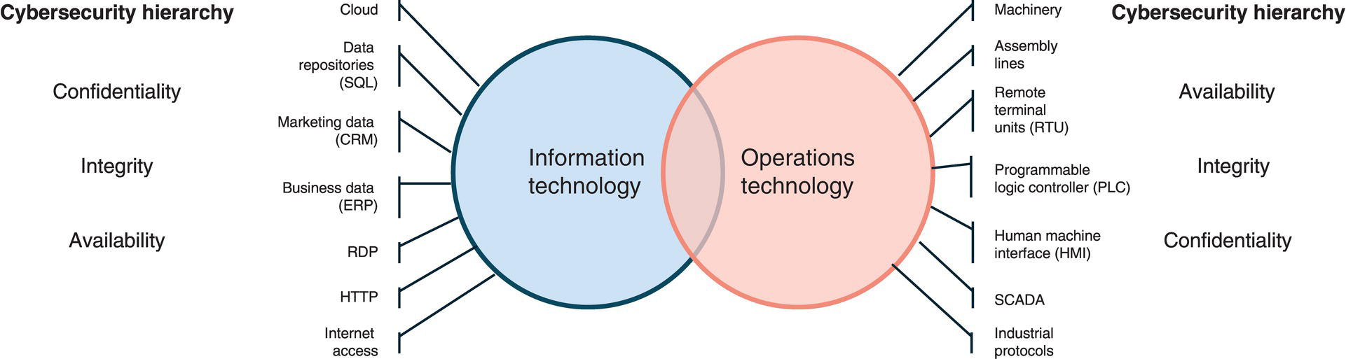
7.16.1 Reference Architecture
7.16.2 Control Layer
7.16.3 Demilitarized Zone
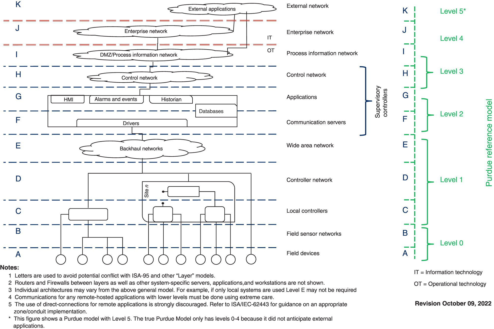
7.16.4 Firewalls and Isolation
7.16.5 Cybersecurity Standard Sources
7.16.6 Management of Change
7.16.7 SCADA User Permissions and Area of Responsibility
7.16.8 Zero Trust
7.17 SCADA Standards
7.18 Pipeline Industry Applications
7.18.1 Leak Detection
7.18.2 Batch Tracking
7.18.3 Dynamic Pipeline Highlight
7.19 Machine Learning and Artificial Intelligence
7.19.1 Overview of an AI ML-Based Application
7.19.2 Predictive Flow Models
7.19.2.1 Data Extraction
7.19.2.2 Data Preparation
7.19.2.3 Model Creation
7.19.2.4 Use Model to Simulate Improvements
7.19.2.5 Model Operation
7.19.2.6 Model Maintenance
7.19.3 Optimization Engines
7.19.3.1 Power Consumption Optimization
7.19.3.2 Throughput Enhancement
7.19.3.3 Man Versus Machine Testing
7.19.4 Decision Support and Autonomous Operations
7.19.4.1 Manual Mode
7.19.4.2 Semi-Autonomous
7.19.4.3 Autonomous
7.19.4.4 Case Study
7.20 Communication Media
7.20.1 Ethernet (Copper) Data Cable
7.20.2 Leased Line
7.20.3 Dial-Up Line
7.20.4 Optical Fiber
7.20.5 Radio Communications
7.20.6 License-Free Spectra
7.20.6.1 2.4 and 5.8 GHz
7.20.6.2 900 MHz
7.20.7 Licensed Radio
7.20.8 Microwave
7.20.9 Satellite
7.20.10 Cellular data
7.20.10.1 GSM
7.20.10.2 5G
7.20.11 Low-Data-Rate Wireless
7.20.11.1 LoRaWAN
7.20.11.2 SigFox
7.21 Communication Infrastructure
7.22 Communications Integrity
7.23 RTUs and PLCs
7.24 Database
7.25 User-Defined Programs
7.26 RTU/PLC Integrity
7.27 Safety Systems
7.27.1 Safety Integrity Level
SIL
Probability of Dangerous Random Failure/Hour (PFH)
Probability of Dangerous Failure on Demand (PFDavg)
4
≥10−9 – <10−8
100,000–10,000
3
≥10−8 – <10−7
10,000–1,000
2
≥10−7 – <10−6
1,000–100
1
≥10−6 – <10−5
100–10
7.27.2 Safety Instrumented System
7.27.3 Black Channel
7.28 IOT/IIOT
7.29 Electrical Classification Compliance
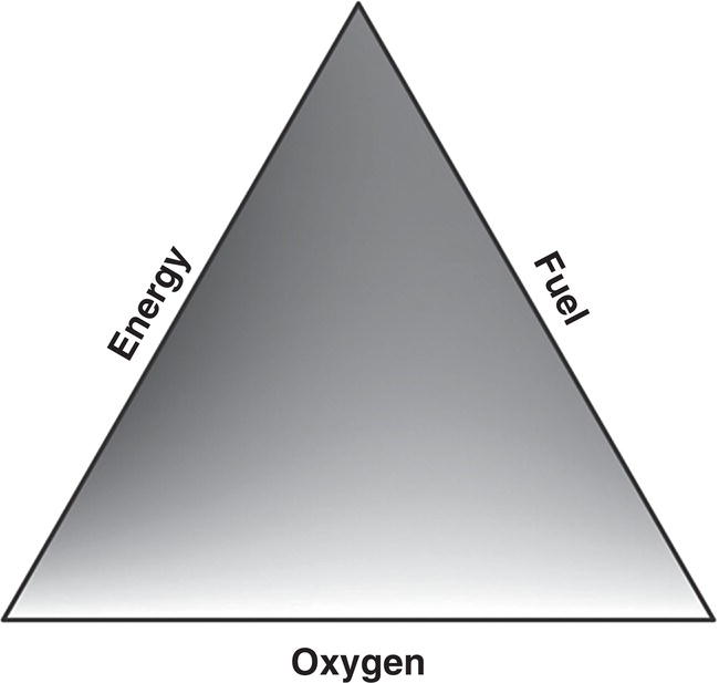
7.29.1 Area Classifications
7.29.1.1 Class Division versus Zones
Typical gas
Class/division
Zone
Acetylene
A
IIC
Hydrogen
B
Ethylene
C
IIB
Propane
D
IIA
7.29.1.2 Explosion-proof
7.29.1.3 Purging
7.29.1.4 Intrinsic Safety
7.30 Acronyms, Abbreviations, and Terms
Acronyms
Explanation
SCADA
Supervisory control and data acquisition: a computerized control system.
RTU
Remote terminal unit: manages data from sensors wired into it.
LAN
Local area network: an Ethernet computer network.
COTS
Commercial off-the-shelf
PLC
Programmable logic controller: similar to an RTU; it manages data from sensors.
DCS
Distributed control system: similar to SCADA but designed for processing plants and other “campus-sized” assets.
HMI (MMI)
Human–machine interface (man–machine interface): a simpler SCADA system focused on data presentation with less (or no) emphasis on higher-level functions.
I/O
Input/output: One I/O point represents a single piece of data at the RTU.
GUI
Graphical user interface: a software interface providing a rich graphical display to human users.
MBPS
Mega bits per second
RAID
Redundant array of independent disks: an arrangement of hard drives that provide high availability service.
Telco
Telecommunications company
IT
Information technology
OT
Operations technology
SIL
Safety integrity level
SIS
Safety instrumented system
Term
Definition
Real Time
The prompt collection and processing of data so that operational decisions can be made before undesired consequences occur.
Controller
A human who uses SCADA to perform pipeline operations.
Popup
A small SCADA display window that shows additional information about a single data point.
Bibliography