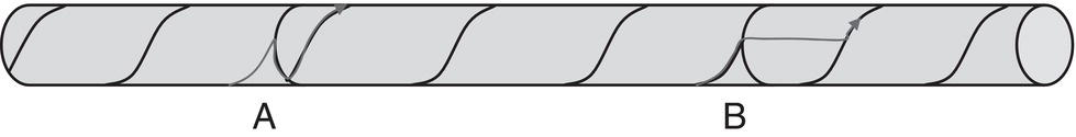
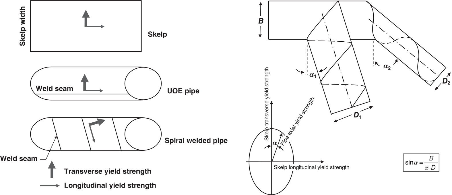
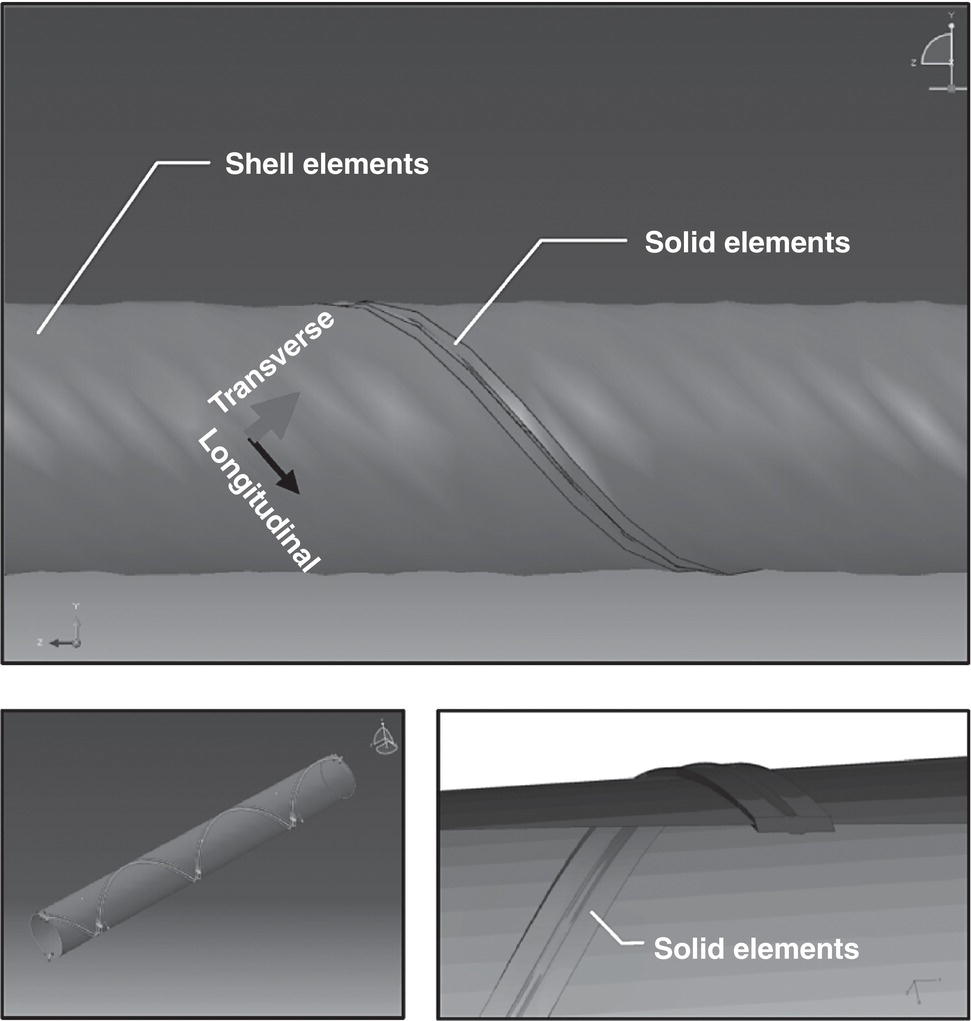
Ayman Eltaher Doha, Qatar The oil and gas (O&G) offshore industry has been interested in spiral welded pipe (SAWH) for some time due to the potential economic benefits and simpler technology involved. The latter implies that a wider range of nations would be able to be involved in their own O&G projects, which has been a target that more nations started to work toward. However, a concern of the industry has been that the performance of the SAWH pipes may be substandard compared with the more established and better accepted types such as seam welded (SAWL), high-frequency induction (HFI) welded, and electric resistance welded (ERW) line pipes and that it does not meet the requirements of the industry standards. To alleviate the concern, a comprehensive program to qualify the type of pipes would be required; such a program would need to include testing and analysis that cover known aspects of mechanical behavior of that pipe type and potential deviation in its response from that of the other better recognized pipe technologies. This chapter presents the main areas of reassurance and concern, with the aim being to help the different parties (operators, designers, etc.) interested in the technology. As discussed in Ref. [1], the use of SAWH pipes has indeed been popular in onshore and very shallow water low-pressure O&G applications, water pipelines, and ship-borne piping. Further interest in the technology has increased, as new SAWH pipe mills started to employ better fabrication technology, with the resulting chemical compositions, mechanical properties, and dimensional tolerances perceived to be comparable to those of the SAWL pipe. Other advantages of the SAWH line pipes are that they can be manufactured and coated in 80 ft lengths, which makes it faster/more economical to install. However, the use of SAWH in high-pressure hydrocarbon transportation has lagged due to concerns related to uncertainties (as opposed to actual negative observations) in the mechanical response of the pipe type as well as issues related to the variability in produced pipe quality. The former is thought to be able to overcome with further research and the latter with improvements in the fabrication process. Indeed, for spiral welded pipes, DNV-OS-F101 [2] recommends further investigation on a number of areas, including fracture arrest, resistance of external pressure, and designing for displacement-controlled conditions. Too few initiatives have been made by the offshore O&G industry to investigate the validity of the above technology gaps and possible approaches to close them, with the majority having been proprietary limited scope projects. As one of the bigger published efforts to date, Det Norske Veritas (USA), Inc. (DNV) and MCS Kenny led a joint industry project (JIP) that investigated and published information on the suitability of SAWH pipe for shallow offshore applications [1, 3]. Minimal work on the subject is available in the public domain. Therefore, this chapter depends mainly on the work carried out in above-mentioned JIP (hereafter referred to as “the JIP”) and released to the public domain in Refs [1, 3]. The first phase of the JIP [1] carried out a state-of-the-art review of the use of SAWH line pipe for offshore applications and identified knowledge gaps where further work has a potential to clarify how and where this type of line pipe can be used in subsea pipelines. In order to assess the readiness of SAWH pipe for use offshore and to identify which critical issues need to be considered in the JIP, a technology assessment per DNV-RP-A203 [4] was performed. In the assessment, criticality of an issue was identified as a function of both its severity and expected frequency. A review of a number of design and line pipe standards (namely, DNV-OS-F101 [2], API RP 1111 [5], ASME B31.8 [6], and API 5L/ISO 3183 [7, 8]) was also carried out as part of the JIP in order to see how they address SAWH pipe, with the conclusion having been that none of the reviewed standards fully cover the use of SAWH pipe for offshore applications, which supported the need for further work. The second phase of the JIP [3] focused on qualifying commonly manufactured spiral welded pipe sizes for shallow offshore applications, using finite element analysis (FEA). Limiting the scope to shallow water also puts an emphasis on the S-lay pipelay procedure and conditions. In particular, the FEA qualification process aimed at comparing the limit states of SAWH line pipe under different loading conditions (e.g., axial tension and bending) with those of the more commonly used seamless and UOE (SAWL) pipes. As part of the JIP investigation, relevant installation and operation conditions (e.g., water depths, environmental loading, and typical installation vessel characteristics) were studied together with readily available pipe sizes. The conclusion of the study was that SAWH pipes are not a relevant option beyond the fairly shallow water depth of about 240 m. Spiral welded pipelines in water depths shallower than 240 m were then studied in more detail, with S-lay considered the relevant method of installation, and refined operational, environmental, and installation vessel configuration (e.g., fixed or floating stinger) and motion data were addressed. In the study, data were compiled from actual fields where SAWH pipe might be an option. The lines in these fields were found to have diameters that were in the lower range of what is generally considered feasible for SAWH pipe. Oil, gas, water injection, and water disposal service were identified as areas where SAWH pipe could be an option. The challenges below were considered by the JIP [1] as key to possible deviation in the response of SAWH pipes compared with other types more commonly used by the industry. As stated in DNV-OS-F101, these issues may not be critical but are highlighted due to lack of knowledge. It is generally believed that certainty and reliability of stress analysis of SAWH pipes are rather lower than those for other types commonly used by the O&G industry, due to the challenges discussed below, and the thought is that allowable levels of stresses and strains should be accordingly reduced (again, relative to those established for other types of pipes). As discussed in Ref. [1], dimensional quality of produced SAWH pipe welds greatly depends on the dimensional quality of the coil. In particular, pipe out of roundness, weld peaking, and weld bead height and shape are of importance to offshore applications, especially for deeper water. Although one could argue that these parameters (for common currently fabricated SAWH pipes) are not consistently up to the offshore standards, they could be improved with careful control of production processes. On the other hand, the following concern is attributed to the characteristic shape of the spiral weld and not apt to be solved through improvement of the production processes: namely, the fact that principal directions of the steel plate material properties are different from the principal directions of the pipe geometry. This is due to the hot rolling process of manufacturing of the steel plates, as shown in Figure 11.2. Depending on the specific pipe helical angle, axial and hoop strengths and stiffnesses could be higher or lower than anticipated for homogeneous materials. Figure 11.1 Illustration of possible running fracture paths. (Reference [1]/Offshore Technology Conference.) Figure 11.2 Material anisotropic and principal directions of spiral welded pipe. (Reference [1]/Offshore Technology Conference.) Until more experience is accumulated in this area, it is currently believed that spiral welded pipe needs to be modeled and analyzed to the highest level of detail possible. As reported in Refs [1, 3], detailed fully nonlinear three-dimensional (3D) finite element models have been used in the industry and by the JIP. Details of the welds including misalignment were modeled in full (solid-element) 3D, while most of the plain tubular section was modeled with shell elements, as shown in Figure 11.3. Pipe ovality was incorporated when deemed important to the expected response (e.g., collapse), with the anisotropic properties included in most cases since the extent of their influence was not certain. Away from the area of special concern, the SAWH pipe could be modeled using pipe elements, which can be kinematically coupled to the part of the pipe modeled with 3D solid and shell elements. Submodeling was also used to study local effects in further detail. Material and manufacturing parameters of SAWH pipes are important input to design; these include achievable wall thickness and diameter and quality and consistency of material and dimensions. Following are the more prominent challenges related to material properties and failure modes of SAWH pipe [1]: Figure 11.3 Finite element modeling of spiral welded pipe. (Reference [3]/with permission of The International Society of Offshore and Polar Engineers.) As discussed in Ref. [1], test and inspection data of spiral pipe actually supplied for actual projects were compiled as part of the JIP study. It was observed that, in general, the data met the requirements of DNV-OS-F101; however, the following were also noted: Further testing and gathering of test data, particularly on the following, was recommended to fill in the above gaps [1]: dimensional tolerances, ductile–brittle transition curves, weldability, effects of thermal aging, weld residual stress distribution, and NDT procedures and inspection data. Reference [1] described the technology qualification process adopted by the JIP, which followed the approach described in DNV-RP-A203 [4]. Per the RP, the technology under investigation (SAWH pipe) was broken into manageable components that could be assessed. Then, the outcome of the technology assessment was used as input to the failure mode effects and criticality analysis, with the identified critical components and their defined functions evaluated to identify failure modes. Threat assessment was also performed as part of the procedure, aiming to find potential failure modes and mechanisms that could occur in the components identified as critical during the technology assessment. The impact and consequences of those failures were analyzed and ranked based on their risk. The second phase of the JIP focused on implementing an important step of the pipe qualification plan, namely using FEA [3]. The FEA qualification process aimed at identifying the response of SAWH line pipe to different loading conditions (e.g., axial tension and bending) as well as identifying its limit states and comparing these limit states with those of the more commonly used seamless and UOE pipes. However, Ref. [3] emphasized that for the comparison between the analytical responses of the SAWH and seamless/UOE pipes to be valid and meaningful, the spiral pipe material and fabrication quality need to be comparable to that of the seamless/UOE pipe; in other words, the spiral pipe should conform to line pipe requirements of the industry, stated in its codes and standards, such as DNV-OS-F101 [2] and API Spec 5L [7]. Fracture arrest was not discussed in Ref. [3]. Limit states relevant to SAWH line pipes were identified by carrying out FE simulations, using the nonlinear general-purpose FE package, Abaqus [10]. The analysis parameters of these simulations were selected based on the guidance from known limit states of seamless and UOE pipes, particularly as described in DNV-OS-F101 [2], with the following limit states considered: burst, collapse, yielding (due to axial tension), local buckling (due to bending and combined loading), and fatigue. Results of the FEA were compared with a number of relevant benchmark solutions: Limiting the scope to shallow water puts an emphasis on the S-lay pipelay procedure and loads and conditions associated therewith, and as the industry has limited experience with SAWH line pipes subjected to large strains, only pipe with overmatching welds and subject to load-controlled situations was studied. Limited discussion was presented in Ref. [3] as to the conclusion on the performance of the spiral welded pipe compared with seamless and UOE counterparts. However, the example data presented for combined (tension and bending) loading show that failure combinations of the spiral welded pipe fell on or outside the envelope predicted by DNV-OS-F101, which indicates that specific pipe configuration is likely to behave at least as good as seamless and UOE pipes, under addressed conditions. Fatigue was also deemed a loading condition of interest, as it is of concern during installation conditions using the S-lay procedure and in free span situations [3]. To address this limit state, the pipe models were subjected to axial and bending loading conditions, and stress concentrations at the hotspots were investigated. Special focus was placed on the spiral weld geometric characteristics and tolerances. Girth welds and their interaction with spiral welds (which could potentially generate atypical stress concentrations) were not addressed, and no conclusion regarding the criticality of the fatigue issue was given in Ref. [3]. Due to the limited amount of information in the subject of SAWH pipes, and specifically for offshore applications, we reference in this section work from other industries concerning spirally welded tubular structures. In particular, Ref. [12] is part of the European research project Combitube and presents data from full-scale four-point bending tests on SAWH structural tubes. Another European project is SBD-SPIPE, which investigates the use of SAWH tubes for demanding applications both onshore and offshore that require good performance under application of large strains. Comparison between data from the investigations of the two industries will surely be useful when the investigations reach reasonable maturity levels. However, caution should be exercised before utilizing such data in the O&G offshore industry, due to the difference in the intended purposes, relevant ranges of D/t ratio, and referenced codes. A state-of-the-art review regarding offshore application of spiral welded pipe is presented in this chapter. However, due to the limited pool of technical references on the topic, majority of the presented material was derived from information published out of the spiral welded pipe JIP [1, 3]. Following is a summary of the ideas and conclusions discussed:
11
Spiral Welded Pipes for Shallow Offshore Applications
11.1 Introduction
11.2 Limitations of the Technology Feasibility
11.3 Challenges of Offshore Applications
11.3.1 Design Challenges
11.3.2 Stress Analysis Challenges
11.3.3 Materials and Manufacturing Challenges
11.4 Typical Pipe Properties
11.5 Technology Qualification
11.6 Additional Resources
11.7 Summary
References