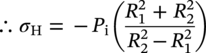
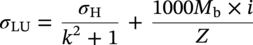
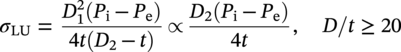
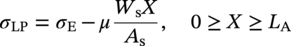
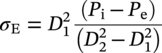
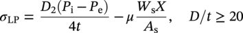
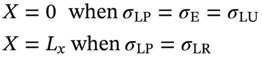
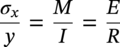
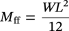
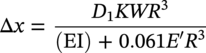
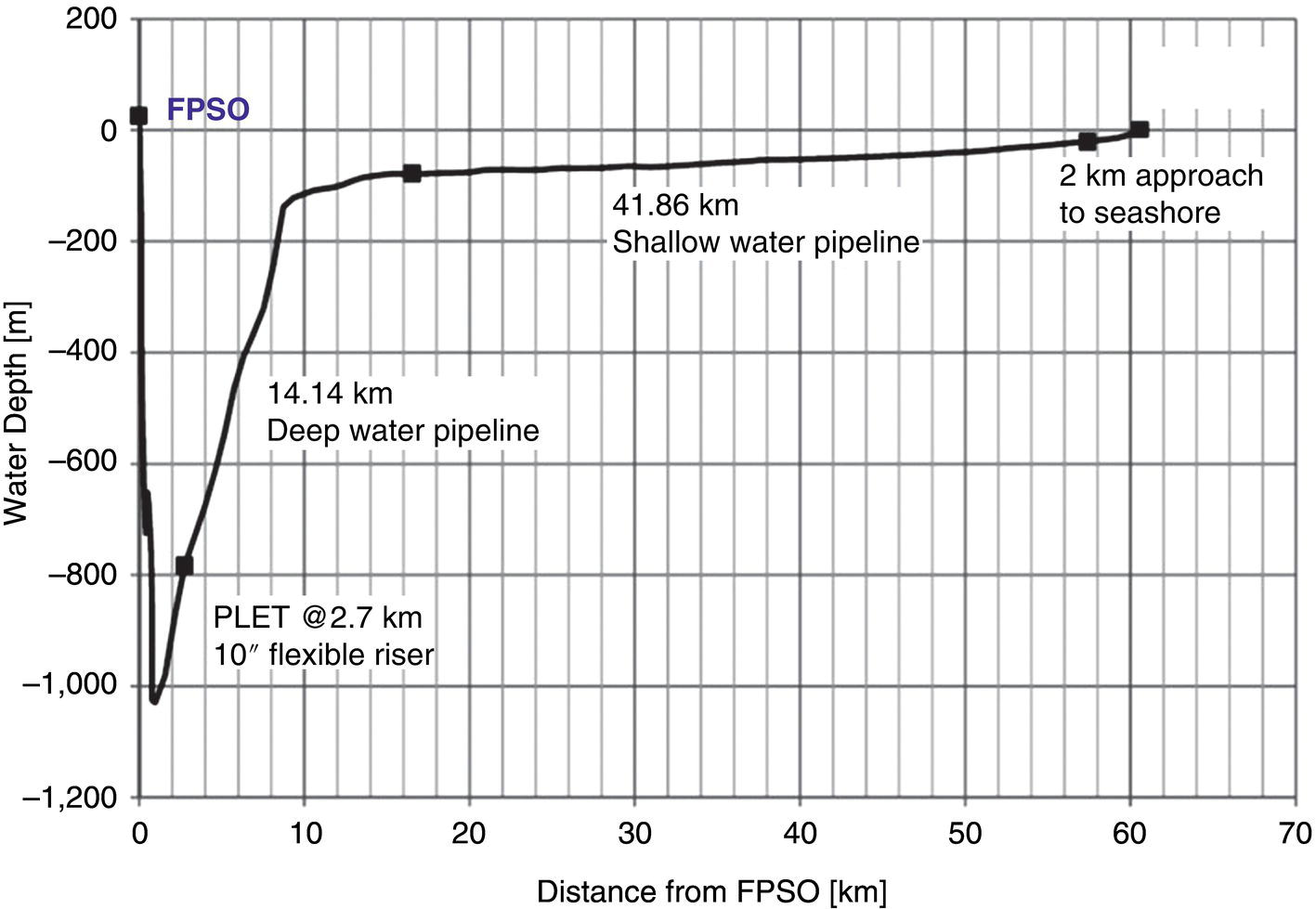
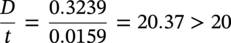
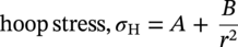
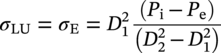
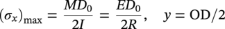
Mavis Sika Okyere Ghana National Gas Limited Company, Accra, Ghana In stress-based design, the pipeline is designed so that the stress on the pipeline is maintained below a prescribed limiting value, the specified minimum yield stress (SMYS), by a safety factor. In this chapter, a reference is made to standards that are used in different jurisdictions, and some comparisons are made among British, Canadian, European, international, and U.S. standards. For more detailed information, readers should refer to the current editions of the relevant standards. As discussed in CSA Z662:23, Section 4.3.5.2 [1], the design formula for a straight pipe is where P is the design pressure (MPa), S is the specified minimum yield strength (MPa), t is the design wall thickness (mm), D is the outside diameter of the pipe (mm), F is the design factor, L is the location factor, J is the joint factor, and T is the temperature factor. The design pressure is the pressure that is used in all equations and stress calculations and is the maximum internal pressure of the pipeline during its design life. The maximum allowable operating pressure (MAOP), maximum operating pressure (MOP), and surge pressure should be considered with the design pressure. Unduly high design pressures require the use of an excessively thick pipe. For a gas pipeline, the pressure in the pipeline does not vary greatly due to elevation, but where the elevation is extreme (hundreds of meters) below the inlet point, the highest pressure in the pipeline and the location of the highest pressure need to be determined. For liquid pipelines, there is always a need to consider elevation, especially when the pipeline is below the inlet point. Normally, it is better to keep a fixed design pressure for the design of the whole pipeline. However, for pipelines with large positive elevation change (i.e., hilly and mountainous zones), the design pressure can be reduced with elevation increases. This will result in different pipes for different sections, complicating the line pipe order and construction, and it makes any future uprating by adding additional pumping stations limited or impossible. Normally, for gas pipelines, the maximum operating pressure does not exceed the design pressure. As per Clause 805.214 of ASME B31.8, the maximum allowable operating pressure is defined as the maximum pressure at which a gas pipeline system is allowed to operate. The value of the MAOP varies and depends on the location and prescribed test pressure [2]. Due to lack of surge pressure in a gas pipeline, the MAOP should not be higher than the design pressure but is often set slightly (5% or less) below the design pressure. For liquid pipelines, the MAOP can be 10% or more below the design pressure due to surge problems. The difference between the MAOP and the design pressure permits shutdown alarms and other protective devices to be set to ensure that the pipeline does not exceed the design pressure [2–9]. Table 10.1 Percentage of Overpressure Permitted [1–9] The maximum operating pressure is equal to the maximum pressure to which the piping system will be subjected in operational conditions. This includes static pressure and the pressure required to overcome friction [2]. Above MOP, a warning alarm might be set, but this will not shut down the pipeline until the pressure increases above the MAOP. To increase the MOP above the MAOP, there is the need to retest the pipeline to a higher pressure in order to increase the MAOP. The allowable overpressure varies between design codes. Table 10.1 outlines the percentage of overpressure that is permitted. Surge pressures in a liquid pipeline are produced by a change in the velocity of the moving stream that results from shutting down of a pump station or pumping unit, closing of a valve, or blockage of the moving stream. Surge pressure decreases in intensity as it moves away from its point of origin [2]. The surge pressure depends on the density of fluid, velocity of fluid, pipe length, speed of closure or shutdown, fluid pressure, and sonic velocity of the fluid. The design codes have limiting values for surge pressure to be added to the MAOP. Surge pressure calculations should be made, and adequate controls and protective equipment should be provided. Gas pipelines do not suffer excessively from surge due to compressibility within the fluid. However, this can become a major issue for liquid pipelines that have a relatively high fluid velocity (>2.5 m/s) or are subject to sudden closure of valves or pumps. Test pressure is set by the design codes to verify that the pipeline is fit for purpose and free from material or construction defects. The setting of the pressure test levels needs to follow the methodology of the design code (e.g., Clause 847.2 of ASME B31.8), but care also needs to be taken not to overstress the pipeline either at its lowest point or when the design calculations have used the empty weight of the pipe, as in gas pipes, and not the temporary weight of the hydrotest water [2]. Pipelines in mountainous or hilly regions are often sectioned into different lengths for testing. The test pressures used in different situations are listed in Table 10.2. Design factors (Table 10.3) have been used since pipeline design codes were first established to provide a defined level of safety and mechanical strength. The design factor to be used is sometimes limited by legislation in a particular country [2–9]. Table 10.2 Test Pressures Source: Adapted from [2]. Table 10.3 Design Factor [2–9] The design codes state where in this range a specific design factor should be used but generally allow a higher factor to be used, provided that this action is supported by a safety evaluation or is subject to scrutiny by the regulatory safety authority. It is appropriate to specify the design factor at a level that takes into consideration the boundary between defect arrest and propagation, also known as the leak/break boundary. The two important design factors are Hoop stress, σH, is the stress in a pipe of wall thickness t acting circumferentially in a plane perpendicular to the longitudinal axis of the pipe, produced by the pressure P of the fluid in a pipe of diameter D and is determined by Barlow’s formula [2]: where σH is the hoop stress (MPa), P is the internal design pressure (gauge) (MPa), t is the pipe wall thickness (m), and D is the pipe diameter (m). The full Lamé equations are simplified for the design of thick-walled pipelines. A pipeline with D/t < 20 is known as a thick-walled pipeline. Taking into consideration a thick-walled pipe, subjected to an internal pressure, Pi, with zero external pressure [10], The two well-known conditions of stress that allow the Lamé constants A and B to be determined are Therefore, from Equations (10.5–10.8), the radial and hoop stresses are calculated as The maximum radial and hoop (circumferential) stresses occur at r = R1 when σr = Pi. The negative sign indicates tension. where σH is the hoop stress (MPa), σ is the radial stress (MPa), R1 is the internal radius (m), R2 is the external radius (m), r is the radius at point of interest (measured from the pipeline center), Pe is the external pressure (gauge) (MPa), and Pi is the internal pressure (gauge) (MPa). A pipeline with D/t > 20 is known as a thin-walled pipeline. A basic approach is known as thin wall hoop stress theory. Since the maximum hoop stress is normally the limiting factor, it is this stress that will be considered [10–12]. It is predictably accurate for D/t > 20. The hoop stress is then calculated as follows: Hoop stress developed in the pipe wall at the internal design pressure is given by where σH is the hoop stress (MPa), Pi is the internal design pressure (gauge) (MPa), Pe is the external pressure (gauge) (MPa), t is the design thickness (m), D1 is the inside pipe diameter (m), and D2 is the outside pipe diameter (m). The estimation of the longitudinal stress in a section of the pipeline requires the individual stress components to be identified knowing external restraining conditions. The axial (longitudinal) stress in a pipeline depends wholly on the limiting conditions (imposed boundary condition) experienced by the pipeline, that is, whether the pipeline is unrestrained, restrained, or partially restrained. The boundary conditions can include the effects of soil reaction loads, anchor restraints, line pipe bend resistance, and residual pipelay tension forces [10–12]. The longitudinal stress in a thin cylindrical shell is calculated as half of the hoop stress. The total longitudinal stress should be the sum of the stresses arising from the following (see Sections 10.4.2.1–10.4.2.7): A pipeline should be considered totally restrained when axial movement and bending resulting from temperature or pressure change are totally prevented. A fully end constrained boundary condition can occur at an anchor block or pig trap and pipeline end manifold (PLEM) or pipeline end termination (PLET) sled. For a fully end constrained pipeline (Figure 10.1), the longitudinal strain (ε1 = 0) and deflection (Δ = 0) components are 0, and the longitudinal stress response can be determined from Equation (10.15), assuming a constant uniform temperature field [10–12]. Piping in which soil or supports prevent axial displacement of flexure at bends is restrained. Restrained piping may include the following [2, 6]: Figure 10.1 Longitudinal tensile stresses in a fully restrained pipe section. The net longitudinal compressive stress in a restrained pipe is calculated based on Clause 419.6.4 of ASME B31.4 as where σLR is the restrained longitudinal stress (MPa), α is the thermal linear coefficient of expansion (mm/mm/°C), T2 is the operating temperature (maximum or minimum metal temperature) (°C), T1 is the installation temperature (°C), v is the Poisson’s ratio (v = 0.30 for steel), σH is the hoop stress (MPa), and E is the modulus of elasticity (GPa). Piping and equipment should be supported so as to prevent or reduce excessive vibration and should be anchored sufficiently to prevent undue strains on connected equipment. Supports, hangers, and anchors should be so installed as not to interfere with the free expansion and contraction of the piping between anchors. Suitable spring hangers, sway bracing, and so on should be provided where necessary [2]. Anchor blocks are used to stop axial movement of a pipeline. Anchors are normally required when the pipeline comes above ground, prior to pig hatches, other branches, or manifolds. Connection of the pipeline to the anchor block is normally done by the addition of slip-on flanges to the pipeline, which are fillet welded in place. A large concrete block is then constructed around the pipeline to resist the expansion forces. Restrained portions are always prevented from moving by installing anchors and guides, but in a buried line, a large portion is fully restrained by soil friction only [12]. The axial compressive force required to restrain a pipeline can be calculated as follows: where F is the axial force (N), E is the modulus of elasticity (GPa), T1 is the installation temperature (°C), Sh is the hoop stress (MPa), v is the Poisson’s ratio (0.3 for steel), A is the cross-sectional area of the pipe wall (m2), α is the coefficient of thermal expansion (°C−1), T2 is the maximum or minimum metal temperature (°C), k is the ratio of the outside diameter to inside diameter, and P is the internal design pressure (gauge) (MPa). An end-free boundary condition can occur at locations where no physical longitudinal restraint exists, for example, at a riser bend extending from the seabed to the production platform. Since the pipeline is not restrained axially, the Poisson effect and thermal expansion component do not produce stress in the line pipe. The pipeline longitudinal stress is only due to the end cap effect [2–5]. Piping that is free to displace axially or flex at bends is unrestrained. Unrestrained piping may include the following: For unrestrained sections of a pipeline, the longitudinal tensile stress should be calculated as follows (refer to BS 8010, Part 2, Section 2.8, and Clause 2.9.3.2): For a thin-walled pipeline, use k = 1. When the internal pressure is greater than the external pressure, the stress will be positive and tensile, as expected. The unrestrained longitudinal stress can generally be expressed as Expanding Equation (10.19), the expression for an approximate thin wall is given as where σLU is the unrestrained longitudinal stress (MPa), Mb is the bending moment (N m), D1 is the inside diameter (m), D2 is the outside diameter (m), Z is the pipe section modulus (m3), σE is the end cap stress (MPa), i is the stress intensification factor (see Section 10.6.1), and k is the ratio D2/D1. At the free end of a pipeline, the total friction force acting on the pipeline increases as one progresses from the free end. This friction is passive and acts against the forces that try to displace the line [2, 4, 5]. For a constant frictional force per unit length of the line, the rate of change of longitudinal stress is constant. The expression for the longitudinal stress experienced by a pipeline that is partially restrained is given as Expanding the above, the expression for an approximate thin wall is given as [5] where μ is the seabed coefficient of friction, Ws is the submerged weight of the pipeline, X is the distance from the free end of the pipeline (m), As is the area of steel (As = πDt) (m2), and Lx is the length between anchors (m). Note A pipe must sustain installation loads and operational loads. In addition, external loads such as those induced by waves, current, uneven seabed, trawl-board impact, pullover, and expansion due to temperature changes need to be considered. A pipe subjected to increasing bending may fail due to local buckling/collapse or fracture, but it is the local buckling/collapse limit state that usually dictates the design [13]. The pipe (beam) bending is analyzed using the engineer’s theory of bending (ETB) and simple beam theory. The theory associates the bending stress at a point to the moment imposed on the section or the curvature experienced. It is used to calculate the bending stress at any point in a pipe. Assumptions The equation is valid for elastic pure bending and does not take into account the geometrical deformations that occur, particularly in hollow cylinders (ovality) under bending. The equation is expressed as This is called the engineer’s theory of bending. The standard form of this equation is where σx is the bending stress (0 ≤ σx ≤ σy) (MPa), M is the bending moment (N m), y is the distance from the neutral axis (0 ≤ y ≤ OD/2) (m), I is the moment of inertia (kg m3), E is the Young’s modulus of elasticity (GPa), and R is the radius of curvature (m). Therefore, knowing the applied bending moment and the location of the centroid, the second moment of area and the stresses along the depth of the pipe section can be calculated. In the simple theory of bending of beams, it is assumed that no appreciable distortion of the cross-section takes place so that there is no displacement of the material either toward or away from the neutral axis. For a thin-walled pipe subjected to bending, movement of the fibers toward the neutral axis does occur [14]. The maximum bending moment and hence the bending stress at any point in the cross-section can be determined by assuming a beam configuration. A fixed–fixed beam under a uniformly distributed load gives a maximum bending moment (Mff) at the fixed ends of the beam. A beam with pinned supports under a uniformly distributed load gives a maximum bending moment (Mpp) at midspan. It is commonly accepted that a real beam configuration for an unrestrained pipeline resting on the seabed is somewhere between the fixed–fixed and the pinned–pinned cases and is given a value as follows: where Mff is the fixed–fixed bending moment, Mpp is the pinned–pinned bending moment, W is the uniformly distributed load (per meter), L is the length of pipeline span, and Mfp is the bending moment halfway between the fixed–fixed and the pinned–pinned cases. The stages of longitudinal stresses connected with bending are as follows: On the other hand, this can be solved by drawing the bending moment diagram, that is, if the value of the bending moment, M, is determined at various points of the beam and plotted against the distance x measured from one end of the beam. It is further facilitated if a shear diagram is drawn at the same time by plotting the shear, V, against x. This approach facilitates the determination of the largest absolute value of the bending moment in the beam. Sustained loads are the sum of dead weight loads, axial loads caused by internal pressure, and other applied axial loads that are not caused from temperature and accelerations [3]. In accordance with ASME Boiler and Pressure Vessel Code, Section III, Subsections NC and ND, the calculated stresses due to pressure, weight, and other sustained mechanical loads must meet the allowable 1.5Sh, that is, where T is the temperature derating factor, P is the internal design pressure (MPa), D0 is the outside diameter of the pipe (m), Z is the section modulus of the pipe (m3), MA is the resultant moment loading on the cross-section due to weight and other sustained loads (N m), Sh = 0.33SuT, at the maximum installed or operating temperature (MPa), and Su is the specified minimum ultimate tensile strength (N/m2). Occasional loads are loads such as wind, earthquake, breaking waves or green sea impact loads, and dynamic loads such as pressure relief, fluid hammer, or surge loads. In accordance with ASME Boiler and Pressure Vessel Code, Section III, Subsections NC and ND, the calculated stress due to pressure, weight, other sustained loads, and occasional loads must meet the allowable stress as follows [3]: where Pmax is the peak pressure (MPa) and MB is the resultant moment loading on the cross-section due to occasional loads, such as thrusts from relief and safety valves, loads from pressure and flow transients, and earthquake, if required. For earthquake, use only one-half of the range. Effects of anchor displacement due to the earthquake may be excluded if they are included under thermal expansion. kSh = i.85Sh for upset condition but not greater than 1.5Sy, 2.25Sh for the emergency condition but not greater than i.85Sy, and 3.0Sh for the faulted condition but not greater than 2.0Sy. Sh = 0.33SuT, at the maximum installed or operating temperature (MPa), Su is the specified minimum ultimate tensile strength (N/m2), and Sy is the material yield strength at a temperature consistent with loading under consideration. Thermal expansion may be detrimental for the pipe itself, flanges and bolts, branch connections, pipe supports, and connected equipment such as pumps and compressors. Sufficient pipe flexibility is necessary to prevent such detrimental loads [2]. Stresses due to expansion for those portions of the piping without substantial axial restraint shall be combined in accordance with the following equation (refer to Clause 833.8 of ASME B31.8): The cyclic stress range SE ≤ SA, where If Equation (10.32) is not met, the piping may be qualified by meeting the following equation: where SE is the stress due to expansion (MPa), SA is the allowable stress range for expansion stress, f is the stress range reduction factor, ME is the range of resultant moment due to thermal expansion (N m), also includes moment effects of anchor displacements due to the earthquake if anchor displacement effects were omitted from occasional loadings, Sc = 0.33SuT, at the minimum installed or operating temperature (MPa), Sh = 0.33SuT, at the maximum installed or operating temperature (MPa), Su is the specified minimum ultimate tensile strength (N/m2), SL is the unrestrained longitudinal stress (N/m2), T is the temperature derating factor, i is the stress intensification factor (see Section 6 or Appendix E of ASME B31.8), Mi is the in-plane bending moment (N m), Mt is the torsional moment (N m), Mo is the out-of-plane bending moment (N m), io is the out-of-plane stress intensification factor (refer to Appendix E of ASME B31.8), and ii is the in-plane stress intensification factor (refer to Appendix E of ASME B31.8). Shear stress in a pipeline should be minimized. The shear stress should be calculated from the torque and shear force applied to the pipeline using the following equation: where τ is the shear stress (N/m), T is the torque applied to the pipeline (N m), Fs is the shear force applied to the pipeline (N), A is the cross-sectional area of the pipe (m2), and Z is the section modulus of the pipe (m3). Sections 10.4.3.1 and 10.4.3.2 show how to determine shear stress due to torsion and spanning, which makes up the total shear stress. Torsion is the twisting of a straight bar when it is loaded by twisting moments or torques that tend to produce rotation about the longitudinal axes of the bar. When subjected to torsion, every cross-section of a circular shaft remains plane and undistorted, and the bar is said to be under pure torsion [15]. The shear stress on a uniform cylindrical shaft that is under a uniform torsion is given by For a thin cylindrical shaft (or thin-walled tube) with t < R/10, The maximum shear stress due to torsion can be calculated as follows: where τ is the shear stress (N/m); T is the torque or twisting moment (N m); R is the radial distance from the longitudinal axis (m); Ix and Iy are the moments of inertia about the x– and 33 y-axis, respectively (kg m3); Z is the section modulus (m3); and J is the polar moment of inertia. The shear stress due to spanning is composed of vertical shear and a longitudinal shear due to the bending. The maximum shear force acting on a simple span is equal to the maximum support reaction. This is in turn equal to the change in shear force at the reaction. The maximum vertical shear stress is defined as the force per unit area. The maximum vertical shear stress is calculated as follows [15]: where Fs is the shear force applied to the pipeline (N), As is the cross-sectional area of the pipe (m2), and Rmax is the maximum vertical reaction on the pipe (N). Pressure and temperature as well as other operating conditions such as bending can create expansion and flexibility problems, and therefore stress criteria are specified in all codes, limiting the level of combined stresses allowed in a pipeline. The design factor relates only to hoop stress; if other stresses are significant, then these could contribute to the pipeline steel, exceeding its yield stress. Design codes vary in the way they calculate the combined or equivalent stress, but the following equation is typical [2–9]. The equivalent stress corresponds to the total stress in the pipeline resulting from a combination of all the stresses. The equivalent stress can be calculated using the following equation (refer to DNV 2012, Clause 103): where σe is the equivalent stress (N/m2), σH is the hoop stress (N/m2), σL is the longitudinal stress (N/m2), and τ is the shear stress (N/m2). In accordance with Clause 833.4 of ASME B31.4, the maximum allowable equivalent stress is 90% of the SMYS. Pipe structures should be designed by considering the limit states at which they would be unfit for their intended use by applying appropriate factors. With reference to BS 8010, Part 3, Clause 4.2.5.4, stress in the pipeline system should satisfy the following inequality: The allowable stress depends on the pipe material used, the location of the pipe, the operating conditions, and other limitations imposed by the designer in conformance with the code used. The allowable stresses for various grades and types of material are tabulated in Table 402.3.1(a) of ANSI B31.4, 1992 edition. In accordance with ASME B31.4, for an unrestrained pipeline, the allowable effective stress is 0.72Sy, and for a restrained line, the allowable stress is 0.9Sy. With reference to Clause 833.3 of ASME B31.8, for a restrained pipe, the allowable longitudinal stress is 0.9SyT, where Sy is the specified minimum yield strength (MPa) and T is the temperature derating factor. Based on Clause 833.6 of ASME B31.8, for an unrestrained pipe, the allowable longitudinal stress is σAL ≤ 0.75SyT, where Sy is the specified minimum yield strength (MPa) and T is the temperature derating factor [2]. The allowable hoop stress may be calculated using the following equation (refer to Clause 805.234 of ASME B31.8 and Clause 201.4.1 of API RP 1111): where σaH is the allowable hoop stress, Sy is the specified minimum yield strength, f is the design factor, e is the weld joint factor, and T is the temperature derating factor. The allowable hoop stress for the cold-worked pipe is 75% of the above value (Clause 201.4.4 of API RP 1111). The design factor is 0.72 for pipelines and liquid risers, 0.60 for gas risers, and 0.50 for gas platform piping [2]. In accordance with Clause 833.4 of ASME B31.4, the maximum allowable equivalent stress is 90% of the SMYS. where σae is the allowable equivalent stress and Sy is the specified minimum yield strength. The sum of the longitudinal stresses due to pressure, weight, and other sustained external loads shall not exceed 0.72SA, where SA = 0.75Sy (Sy is the specified minimum yield strength) [6]. The sum of the longitudinal stresses produced by pressure, live and dead loads, and other sustained loadings and of the stresses produced by occasional loads, such as wind or earthquake, may be as much as 1.33Sh [6]. The computed displacement stress range (expansion stress range) SE in a pipeline should not exceed the allowable displacement stress range SA [6]. When Sh is greater than SL, the difference between them may be added to the term 0.25Sh; in that case, the allowable stress range is calculated as where SE is the expansion stress range = where N is the equivalent number of full displacement cycles during the expected service life of the piping system. Fatigue is a structural damage that occurs when a pipe material is subjected to cycles of stress or strain [16]. Such stresses are normally concentrated locally by structural discontinuities, geometric notches, surface irregularities, damage defects, and so on. ASME B31.4 shows how to design the pipeline against fatigue failure. Pipelines can vary in pressure over hourly, daily, or yearly cycles [16]. Pressure cycling can cause small weld defects to grow in time to a critical size and can be a major factor in determining the fatigue life of welded steel gas pipelines, particularly those pipelines designed for use as line-pack storage. (Gas can be stored temporarily in the pipeline system through a process called line packing.). Fatigue is more critical in oil pipelines than gas pipelines because limited compressibility enhances pressure cycling. ASTM defines fatigue life as the number of stress cycles of a specified character that a specimen sustains before failure of a specified nature occurs. Fatigue life may be affected by cyclic stress state, geometry, surface quality, material type, residual stresses, size and distribution of internal defects, air or vacuum, direction of loading, grain size, environment, temperature, and crack closure [17]. To avoid fatigue failure of a pipeline, the following should be adhered to [8]: The significance of the fatigue limit is that if the material is loaded below this stress, then it will not fail, regardless of the number of times it is loaded [16]. In accordance with IGE/TD/1, 15,000 cycles at 125 N/mm2 has been set as the maximum permissible fatigue life. Figure 10.2 Typical generic S–N curves for steel. A very useful way to visualize time to failure for a specific material is with the S–N curve. This is a graph of the magnitude of a cyclic stress (S) against the logarithmic scale of cycles to failure (N). A fatigue life test should be conducted for the pipe material and an S–N curve drawn [16]. For instance, a specimen of the pipe material is placed in a fatigue testing machine and loaded repeatedly to a certain stress, σ1. The loading cycles are continued until failure occurs and the number, n, of loading cycles to failure is noted. Then, the test is repeated for a different stress, say σ2; if σ2 is larger than σ1, the number of cycles to failure will be less. If it is smaller, the number of cycles to failure will be more [16]. Eventually, enough data are accumulated to plot an S–N curve. Such curves have the general shape shown in Figure 10.2, where the vertical axis is usually a linear scale and the horizontal axis is a log scale. From Figure 10.2, the smaller the stress, the larger is the number of cycles to produce failure. Fatigue strength curves (S–N curves) for a particular material or structural weldment formation can be found in design standards such as ASME Boiler and Pressure Vessel Code, Section VIII, Division 2, Appendix 5, and BS 7910. Avoid expansion bends and design the entire pipeline to take care of its own expansion. Maximum flexibility is obtained by placing supports and anchors so that they will not interfere with the natural movement of the pipe. Allow for stress intensification factors in components [10]. Expansion joints may be used to avoid pipeline bending (flexure) stress due to the movement of supports or the tendency of the pipe to expand under temperature change. The following should be considered for the use of expansion joints [2]: Formal flexibility analysis for an unrestrained piping system may not be required. The stress intensification factor (SIF) is defined as the ratio of the maximum stress state (stress intensity) to the nominal stress, calculated by the ordinary formulas of mechanics [2]. In piping design, this factor is applied to welds, fittings, branch connections, and other piping components where stress concentrations and possible fatigue failure might occur. Usually, experimental methods are used to determine these factors. The structural analysis of risers, expansion loops, or tee assemblies entails the use of flexibility stress intensification factors applicable to accurately model the structural behavior of bends and tees within the system. It is recognized that some of the SIFs for the same components are different for different codes. In some cases, different editions of the same code provide different SIFs for a given component. The way that the SIFs are applied to moment loadings is also different for different codes. The B31.1 and ASME Section III codes require that the same SIF be applied to all the three-directional moments, while the B31.3, B31.4, B31.5, and B31.8 codes require that different SIFs be applied to the in-plane and out-of-plane moments, with no SIF required for torsion. Therefore, the stress analyst has to ensure that the appropriate SIFs from the applicable code are used [2]. Flexibility is added in a pipe system by changes in the run direction (offsets, bends, and loops) or by use of expansion joints or flexible couplings of the slip joint, ball joint, or bellow type. In addition, more or less, flexibility can be added by changing the spacing of pipe supports and their function (e.g., removal of a guide close to a bend to add flexibility). Another way to increase the flexibility is to change the existing piping material to a material with a higher yield or tensile strength or to a material quality that does not need additional corrosion and erosion allowance and thereby obtains a reduction in the wall thickness that again gives more flexibility since the moment of inertia is reduced with a reduction of the pipe wall thickness. The flexibility factors and stress intensification factors that can be used are listed in standards, for example, ASME B31.8, Table E1, and CSA Z662:23, Table 4.8. Additional wall thickness is added to account for corrosion when water is present in a fluid along with contaminants such as oxygen, hydrogen sulfide (H2S), and carbon dioxide (CO2). This is one of the several methods available to mitigate the effects of corrosion and often the least recommended [18]. Corrosion allowance is made to account for corrosion loss during service, damage during fabrication, transportation, and storage. A value of 1/16 in. may be appropriate. A thorough assessment of the internal corrosion mechanism and rate is necessary before any corrosion allowance is taken. Refer to BS 8010, ASME codes, ISO, API 5L, and other governing codes for the use of corrosion allowance in the design of pipelines [19]. There is no need for internal corrosion allowance if the substance being transmitted is noncorrosive, for example, dry natural gas [8]. An internal corrosion allowance should be added to the wall thickness calculation when corrosive substances such as wet gas, hydrocarbon liquid, or two-phase flow are being transported through the pipeline [19]. A wall thickness allowance for corrosion is not required if the pipe and components are protected against corrosion in accordance with the requirements and procedures prescribed in ASME B31.4, ASME B31.8, and other governing codes (i.e., coated and cathodically protected) [2–9]. This section shows how to add corrosion allowance to the calculation of the nominal wall thickness of a pipeline, using any of the engineering codes listed below [2–9]. where tcorr is the corrosion allowance (m), tnom is the nominal wall thickness (m), P is the design pressure (MPa), Sy is the specified minimum yield strength (MPa), t is the design wall thickness (m), D is the outside diameter of the pipe (m), F is the design factor, and E is the joint factor. With reference to DNV 2012, Clause 205, the possible strengthening effect of weight coating on a steel pipe is not normally taken into account in the design against yielding. Coating that adds significant stiffness to the pipe may increase the stress in the pipe at discontinuities in the coating. When appropriate, this effect should be taken into account. For the buried pipe, resistance to external loading is a function of pipe stiffness and passive soil resistance under and adjacent to the pipe. The overall stiffness of a long section of the pipeline should be calculated from the value for the moment of inertia and should be used to calculate the overall deflections and induced bending moments for the concrete-coated pipe [20]. Under load, the individual components of the pipe wall (steel, mortar lining, and, when applicable, mortar coating) act together as laminated rings. The combined action of these elements increases the overall moment of inertia of the pipe, over that of the steel pipe alone [20]. The pipe wall stiffness is the sum of the stiffness of the bare pipe, lining, and coating. The pipe wall stiffness (EI) is the sum of the stiffness of the bare pipe, lining, and coating. where t is the wall thickness of the pipe, lining, or coating; (EI) is the pipe wall stiffness per inch of pipe length (in./lb); ELIL is the stiffness of the lining; EcIc is the stiffness of the coating (e.g., concrete); EsIs is the stiffness of the steel pipe wall; E is the modulus of elasticity (207 GPa for steel and 27.6 GPa for cement mortar); and I is the transverse moment of inertia per unit length of the pipe wall (in.3 or mm3). The stiffness of each of the laminar rings (i.e., steel pipe, cement mortar lining, and cement mortar coating) is calculated using the modulus of elasticity of the component in GPa and the moment of inertia as a per unit length value, defined as t3/12. Pipe stiffness and passive soil resistance of backfill play a significant role in predicting deflection. M.G. Spangler [21] of Iowa State University published the Iowa formula in 1941. Deflection of a pipeline is calculated using the modified Iowa deflection formula as follows: where Δx is the horizontal deflection of the pipe (m), D1 is the deflection lag factor (1.0–1.5), K is the bedding constant (0.1), R is the pipe radius (m), (EI) is the pipe wall stiffness per meter of pipe length (in./lb, m/kg), E ′ is the modulus of soil reaction (GPa), and W is the external load per unit length of the pipe (dead load (earth load) + live load). Some data on loading are presented in Table 10.4. Spangler hypothesized that if the lateral movement of various points on the pipe ring was known, the distribution of lateral pressures could be determined by multiplying the movement of any point by the modulus of passive resistance, E′. For mathematical convenience, this lateral pressure was assumed to be a simple parabolic curve embracing only the middle 100° arc of the pipe (see Figure 10.3). Table 10.4 Standard HS-20 Highway and E-80 Railroad Loading Source: [20]/AMERICAN (American Cast Iron Pipe Company). He also assumed that the total vertical load was uniformly distributed across the width of the pipe, and the bottom vertical load was distributed uniformly over the width of the pipe bedding [20]. The following terms can be introduced to describe the three separate factors that affect the pipe deflection: The modified Iowa formula can be represented as a load factor Information on the load factor, ring stiffness factor, soil stiffness factor, bedding constant, and deflection lag factor can be obtained from standards of American Concrete Pipe Association [20–22]. The steel pipe is designed as a flexible conduit; considerable deflection can occur without damaging the pipeline. Deflection limitations are a function of the rigidity of the specific lining and coating being used. Figure 10.3 Spangler assumptions for pressure distribution [21]. (Published with permission of American Concrete Pipe Association.) Table 10.5 E Modulus of Soil Reaction Source: [20]/AMERICAN (American Cast Iron Pipe Company). a Standard AASHTO relative compaction. The calculated deflection is limited to 5%, although larger deflections may not affect pipe performance. Limits for pipe deflection for various forms of coating or lining should be obtained from governing standards and codes [20]. Coating that adds significant stiffness to the pipe may increase the stress in the pipe at discontinuities in the coating. When appropriate, this effect should be taken into account. Maximum stresses will develop along the pipeline where there is no concrete coating (i.e., at the field joint) and may be calculated for a known curvature from Equation (10.60). where σB is the bending stress, C is the outside radius of the steel pipe, R is the imposed bending radius, Io is the overall moment of inertia, Is the moment of inertia of bare pipe, and E is the modulus of elasticity. Ovality is generally associated with bending of pipes and affects the integrity of pipe bends. The control of ovality in pipe bending is discussed in this section [13]. The ovality of a pipe section depends on the dimensional tolerances imposed during the pipe bending while installing the pipe to fit the terrain [14]. Based on DNV 2012, Clause 202, ovality of a pipeline is defined in Equation (10.61). This will affect the structural capacity of the pipeline and shall be taken as the maximum ovality prior to loading. The advantage of ovality less than 0.5% is not allowed. Ovality in excess of 3% shall be assessed in line with DNV 2012, Clause D900. Ovalization caused during the construction stage should be included in the total ovality to be used for design [7]. Pipe ovality is calculated as The out of roundness is calculated as where Dmax is the maximum measured inside or outside diameter, Dmin is the minimum measured inside or outside diameter, D is the nominal outside diameter, f0 is the ovality, and O is the out of roundness. With reference to DNV 2012, Clause D1100, a maximum allowable ovalization of 3% applies for the pipeline as the installed condition. Under DNV 2012, Clause D400, a minimum ovalization of 0.5% is to be accounted for in the system collapse check and the combined loading [7]. In accordance with DNV 2012, Clause D1100, the ovality of a pipeline exposed to bending strain may be calculated using Equation (10.63). where The ovalization mechanism results in loss of stiffness in the form of limit point instability, referred to as “ovalization instability” or Brazier effect. Brazier effects describe the influence of ovalization on the buckling of thin shells. Ovalization can be enhanced by applying bending moments and internal or external pressure [23]. Brazier projected that the ovality was related to longitudinal bending strain by a correlation as follows [5, 24]: Based on the work of Calladine, the correlation to be used in resolving the flattening induced by bending is calculated as [5, 23, 24] where ε is the percentage bending strain, D is the nominal diameter (m), and t is the nominal wall thickness (m). This correlation may be used for the diameter-to-wall thickness ratio less than 35. A buried pipe will ovalize under the effects of earth and live loads. The modified Iowa deflection formula may be used to calculate the pipe ovality under earth and live loads [20, 22]. where OD is the pipe outside diameter (m), Δy is the vertical deflection of the pipe (m), D is the deflection lag factor (1.0–1.5), K is the bending constant (0.1), P is the pressure on the pipe due to soil load Pv plus live load Pp (MPa), R is the pipe radius (m), (EI)eq is the equivalent pipe wall stiffness per inch of pipe length (in./lb, m/kg), and E′ is the modulus of soil reaction (MPa). The pipe wall stiffness, (EI)eq, is the sum of the stiffness of the bare pipe, lining, and coating [22]. where ELIL is the stiffness of the lining, EcIc is the stiffness of the coating, and t is the wall thickness of the pipe, lining, or coating. In engineering, the minimum bend radius of a material is a measure of how tightly a piece can be bent before it breaks. Materials that can withstand a high degree of curvature are preferred in construction because they are more versatile, lending themselves to a wider array of industrial applications [11]. Many factors affect the pipe minimum bend radius, and knowing these factors is crucial to building sound structures. In pipe fitting and sheet metal construction, the minimum bending radii of materials depend on their thickness, composition, and skill of the fabricator [25]. where R is the bending radius (m), C is the pipe radius + enamel thickness + concrete thickness (m), σB is the bending stress (MPa), and E is the modulus of elasticity for concrete (103 MPa). where σL is the longitudinal stress (MPa), σB is the bending stress (MPa), Sy is the pipe specified minimum yield strength (MPa), P is the design pressure (MPa), D is the pipe outer diameter (m), t is the pipe wall thickness (m), R is the bending radius (m), E is the modulus of elasticity (103 MPa), C is the pipe radius (m), and F is the stress factor. Generally, the minimum pipe bend radius is required during the installation load case and the operational (in-service) load case [11]. It is usually mandatory to specify the minimum radius of curvature permitted during the installation stage of a pipeline, whether it is S-lay, J-lay, or Tow-out, reeling of a pipeline [11]. The minimum bend radius for the installation condition should be calculated as From Equation (10.45), where (σB)perm is the permissible bending stress (MPa). All other parameters are as defined in Section 10.10.2. where Ra is the minimum as-laid radius and Eperm is the maximum permissible permanent elastic strain. On the other hand, for a pipeline located offshore, the minimum bend (curvature) in order to prevent slippage is calculated by the following equation: where Rsl is the minimum bend to prevent slippage (limiting slippage curvature), To is the normal on bottom tension, Ws is the submerged unit weight, and F is the lateral friction coefficient or the on-bottom friction coefficient. where T0 is the maximum tension, H is the water depth, and Ti is the tension at the inflexion point. Buried pipelines supported by a well-compacted, granular backfill will not buckle due to vacuum (i.e., when the gauge pressure is below atmospheric pressure) in the pipeline system. To confirm the stability of a pipeline, an analysis of the external loads relative to the pipe stiffness can be performed. If the soil and surface loads are excessive, the pipe cross-section could buckle. The ring buckling depends on limiting the total vertical pressure load on the pipe [20, 22]. where σrb is the allowable buckling pressure (MPa), FS is the factor of safety, C is the depth of soil cover above the pipe (m), D is the outside diameter of the pipe (m), Rw is the water buoyancy factor = 1 − 0.33(hw/C), 0 < hw < C, hw is the height of the water surface above top of the pipe, (EI)eq is the equivalent pipe stiffness, E ′ is the modulus of soil reaction (GPa), and B ′ is the empirical coefficient of elastic support. In steel pipelines, buckling occurs when the ovality reaches about 20%. The sum of the external loads should be less than or equal to the pipe’s allowable buckling pressure, σrb. Confirming the resistance of a pipeline to bucking involves an analysis of the external loads relative to the pipe stiffness [20]. The total external load acting on a pipe must be less than or equal to the allowable buckling pressure of the pipe and can be calculated using the following equation: where σrb is the allowable buckling pressure (MPa), γW is the specific weight of water (0.0361 lb/in.3), hw is the height of water above the pipe (in., m), Rw is the water buoyancy factor, Wc is the vertical soil load on the pipe per unit length (lb/in., kg/m), D is the outside diameter (m), and Pv is the internal vacuum pressure (MPa). The total live load acting on a pipe must be less than or equal to the allowable buckling pressure of the pipe. When analyzing the possibility of potential buckling of a pipeline, there is the need to determine the total live loads acting on a pipeline, using the following equation: where WL is the live load on the pipe per unit length (lb/in., kg/m). When the allowable buckling pressure is not sufficient to resist the buckling loads, the soil envelope should first be investigated to increase the allowable E ′ [20]. It is recommended to use propagation criteria for pipeline diameters under 16 in. and a collapse criterion for pipeline diameters above or equal to 16 in. The propagation criterion is out of date and should be used where optimization of the wall thickness is not required or for pipeline installation methods not compatible with the use of buckle arrestors such as reel and tow methods [20]. It is generally economical to design for propagation pressure for diameters less than 16 in. For greater diameters, the wall thickness penalty is too high. When a pipeline is designed based on the collapse criteria, buckle arrestors are recommended. When a pipeline installed above ground is subjected to vacuum, the wall thickness must be designed to resist collapse due to the vacuum. Analysis should be based on pipe functioning in the open atmosphere, absent of support from any backfill material [20]. Collapse pressure, pc, is the pressure required to buckle a pipeline. The collapse pressure should be calculated using Timoshenko’s theory for collapse of a round steel pipe as follows [20]: where Pc is the collapsing pressure (MPa), ts is the steel cylinder wall thickness (m), tI is the cement coating thickness (m), dn is the diameter to the neutral axis of the shell (m), Es is the modulus of elasticity for steel (30 × 106 psi, 207 × 103 MPa), EI and Ec are the moduli of elasticity for cement mortar (4 × 10⁶ psi, 27.6 × 10³ MPa), vs is the Poisson’s ratio for steel (0.30), and vI and vc are the Poisson’s ratios for cement mortar (0.25). The mode of collapse is a function of D/t ratio, pipeline imperfections, and load conditions. A safety factor of 1.3 is recommended. When a pipeline is designed using the collapse criterion, a good knowledge of the loading conditions is required. Propagating pressure, Pp, is the pressure required to continue a propagating buckle. A propagating buckle will stop when the pressure is less than the propagating pressure (refer to DNV 2012, Clause 501). The recommended formula for calculating the propagation criterion is the latest given by AGA [18]. The nominal wall thickness (tnom) should be determined such that where Pp is the propagation pressure (MPa) and Pe is the external pressure (MPa). The recommended safety factor of 1.3 is to account for uncertainty in the envelope of data points used to derive Equation (10.82). In order to check that the pipeline is fit for the purpose for which it was designed, a pressure test of a harmless fluid prior to commissioning is required by most design codes and safety legislation. Most pressure tests of subsea pipelines are done with water, but on some occasions, nitrogen or air has been used. The minimum hydrotest pressure for gas pipelines is equal to 1.25 times the design pressure for pipelines [18]. Codes do not require that the pipeline be designed for hydrotest conditions but sometimes give a tensile hoop stress limit 90% of the SMYS. The pressure test level should be based on design codes and is aimed at This chapter on stress-based design of pipelines has provided a summary of the following: Pipeline design, materials, and construction techniques are documented in design codes, client standards, handbooks, research papers, and so on. Based on research, there is regular improvement in pipeline design, construction methods, and materials, and so it is important to access the most recent information on currently accepted and proven technologies. This case study was part of a project consisting of an offshore pipeline system, a gas processing plant, and an onshore pipeline system that included a main line and a branch line. The offshore pipeline system included a 10-in. flexible riser installed to a FPSO (floating production storage and offloading) system resting on a PLET landing porch, a pipeline end termination (PLET), a 58-km pipeline with 12 in. outside diameter, and a pig launcher/receiver installed at both ends (see Figure 10.4). The objective of this study was to establish that the pipeline meets or exceeds the requirements of standards. The technical details and specification of the offshore gas export pipeline are listed in Tables 10.A.1–10.A.3. From process and hydraulic analysis, the flow rate, pipe diameter, operating temperature, and design pressure are as shown in Tables 10.A.1–10.A.3. Based on the requirement of the ASME B31.8 code, Figure 10.4 Profile of the offshore pipeline system. Table 10.A.1 Pipe Material Properties Table 10.A.2 Pipeline Specification Table 10.A.3 Technical Specification of Pipeline From API 5L Standardized Pipe Schedule Chart, at 12 in. outer diameter and calculated t = 14.9 mm, tnom = 15.9 mm is selected. All parameters are defined in Table 10.A.1. The structural analysis of pipeline systems is concerned with the determination of stress or strain state of a pipeline and the subsequent check of the stress or strain state against a fatigue limit or allowable stress. The general term of structural analysis is indeed very wide, and this chapter considers the more important aspects in relation to pipeline systems in detail. Hoop stress is calculated using the Barlow’s formula (Equation 10.4) as With reference to Section 10.4.1.2, the standard dimension ratio is Therefore, the offshore pipeline is a thin-walled pipeline. For a deep-water application, the external hydrostatic pressure should be accounted for by using ∆P instead of P for hydrostatic conditions, where, H is the pressure head and ɤ is the unit weight of water. All other parameters are as defined in Sections 10.4.1.1 and 10.4.1.2. A fully end constrained boundary condition occurs at pipeline end manifold (PLEM) or pipeline end termination (PLET) sled of the offshore pipeline, 2-km section buried and restrained by soil friction. In accordance with section 833.2 of ASME B31.8, the net longitudinal stress is calculated as The longitudinal stress due to internal pressure in a fully restrained pipeline is calculated as The net longitudinal stress due to thermal expansion in a fully restrained pipeline is calculated as All parameters are as defined in Section 10.4.2. The bending stress is calculated using the engineer’s theory of bending in Section 10.4.2.4 and Equation (10.26). Radius of curvature of the bent pipe, R Bending stress Maximum bending stress All parameters are defined in Section 10.4.2.4. The axial compressive force required to restrain a thin-walled pipeline can be calculated Equation (10.16) as follows: Cross-Sectional Pipe Wall Area The cross-sectional wall area or area of the piping material can be calculated as All parameters are defined in Section 10.4.2.1. An end-free boundary condition can occur at locations where no physical longitudinal restraint exists; for example, at a riser bend extending from the seabed to the production platform or PLET (see Figure 10.4). The unrestrained longitudinal stress in an operational pipeline can generally be expressed as The longitudinal stress due to internal pressure in an unrestrained pipeline is calculated as The bending stress is calculated using the engineer’s theory of bending in Equation (10.26) as Radius of curvature, R R = radius of curvature of the bent pipe, m Bending stress, With reference to Section 10.4.2.4 and Equation (10.25), Maximum bending stress, All parameters are defined in Section 10.4.2.4. In accordance with Section 10.4.2, the total longitudinal stress is calculated as where In accordance with Section 10.4.4, and Equation (10.43), equivalent stress in the pipeline is All parameters are defined in Section 10.4.4. Design factor, F = 0.72 Specified minimum yield strength for X65M, Sy = 450 MPa Pipe material grade = API 5L X65M PSL2 For a restrained pipeline, the allowable longitudinal stress is 0.9 Sy × T, (refer to Equation (10.43) and Section 10.4.5) Therefore, the requirements of the code are met with respect to longitudinal stress in the restrained section. All parameters are defined in Section 10.4.5. Based on Clause 833.6 of ASME B 31.8, for an unrestrained pipe, the allowable longitudinal stress is σAL ≤ 0.75 Sy × T, where Sy is the specified minimum yield strength, (MPa), and T is the temperature derating factor Therefore, the requirements of the code are met with respect to longitudinal stress in the unrestrained section. In accordance with Equation (10.41), The calculated hoop stress σH = 160.49474 MPa Therefore, the requirements of the code are met with respect to hoop stress All parameters are defined in Section 10.4.5.1. The maximum allowable equivalent stress is 90% of the SMYS (refer to Section 10.4.5, and Equation (10.45)) Therefore, the requirements of the code are met with respect to equivalent stress. All parameters are defined in Section 10.4.5.2. As per clause 833.7 of ASME B 31.8, no formal analysis is required in systems which are of uniform size, have no more than two points of fixation, no intermediate restraints, and fall within the empirical equation below. where Calculation of L and U is based on Figure 10.4. K = 208.3 For SI units or K = 0.03 for FPS units Calculate displacement due to thermal expansion. The entire offshore system is considered, i.e., both riser and the entire offshore pipeline system. The change in length of the thin-walled pipeline is determined from the thermal strain. The flexibility criterion is less than 208.3; therefore, no further or formal flexibility analysis is required. That is, The ASME code does not provide a formula to check for collapse resistance; thus, the API RP-1111 is used. The recommended formula for calculating the propagation criterion is the latest given by AGA (1990) During installation, During operation, Where,ε is bending strain, P0 is external pressure, Pi is internal pressure, fo is collapse factor, (0.7 for seamless or ERW pipe), v is Poisson’s ratio (0.30 for steel), ɤ is sea water density, and Pp is propagation pressure. The stress analysis shows that the design meets the requirements of ASME B31.8, BS 8010, API RP-1111, DNV—OS- F101, and IGE/TD/1.
10
Stress-Based Design of Pipelines
10.1 Introduction
10.2 Design Pressure
10.2.1 Maximum Allowable Operating Pressure
ASME B31.8
ASME B31.4
PD 8010
IGE/TD/1
ISO 13623
EN 1594
CSA Z662
Relating to
N/A
DP
DP
MOP
MAOP
MOP
MOP
%
0
10
10
10
10
15
10
10.2.2 Maximum Operating Pressure
10.2.2.1 Overpressure
10.2.3 Surge Pressure
10.2.4 Test Pressure

10.3 Design Factor
Test Pressure (TP)
Pressure Factor (PF)
Installed pipeline system
TP = MAOP × 1.25
1.25
Offshore platform piping
TP = MAOP × 1.4
1.4
Offshore pipeline risers
TP = MAOP × 1.4
1.4
ASME B31.8
ASME B31.4
PD 8010
IGE/TD/1
ISO 13623
EN 1594
Design factor (liquid)
–
0.72
0.72
–
0.77
–
Design factor (gas)
0.40–0.80
–
0.30–0.72
0.30–0.80
0.45–0.83
0.72
10.4 Determination of Components of Stress
10.4.1 Hoop and Radial Stresses
10.4.1.1 Thick Cylinders


10.4.1.2 Thin-Walled Pipeline

10.4.2 Longitudinal Stress
10.4.2.1 Fully Restrained Pipeline

10.4.2.2 Unrestrained Pipeline
10.4.2.3 Partially Restrained Pipeline
10.4.2.4 Bending Stress
Beam Configurations
10.4.2.5 Stress due to Sustained Loads
10.4.2.6 Stress due to Occasional Loads

10.4.2.7 Stress due to Thermal Expansion


10.4.3 Shear Stress

10.4.3.1 Shear Stress due to Torsion

10.4.3.2 Shear Stress due to Spanning
10.4.4 Equivalent Stress
10.4.5 Limits of Calculated Stress
10.4.5.1 Allowable Hoop Stress
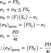
10.4.5.2 Allowable Equivalent Stress

10.4.5.3 Limits of Calculated Stress due to Sustained Loads
10.4.5.4 Limits of Calculated Stress due to Occasional Loads
10.4.5.5 Limits of Calculated Stress due to Expansion Loads


 (MPa), ME is the resultant bending stress =[(iiMi)2 + (ioMo)2]1/2/Z (MPa), St is the torsional stress = Mt/2Z (MPa), Mi is the in-plane bending moment (N m), Mo is the out-of-plane bending moment (N m), Mt is the torsional moment (N m), ii is the in-plane stress intensification factor, io is the out-of-plane stress intensification factor, Z is the section modulus of the pipe (m3), Sc = 0.33SuT, at the minimum installed or operating temperature (MPa), Sh = 0.33SuT, at the maximum installed or operating temperature (MPa), Su is the specified minimum ultimate tensile strength (MPa), and f is the stress range reduction factor (obtained from Table 302.3.5 of ASME B31.3) or calculated as follows:
10.5 Fatigue
10.5.1 Fatigue Life
10.5.2 Fatigue Limit

10.5.3 S–N Curve
10.6 Expansion and Flexibility
10.6.1 Flexibility and Stress Intensification Factors
10.7 Corrosion Allowance
10.7.1 Internal Corrosion Allowance
10.7.2 External Corrosion Allowance
10.7.3 Formulas


10.8 Pipeline Stiffness
10.8.1 Calculation of Pipeline Stiffness


10.8.1.1 Deflection
Highway HS-20 Loading
Railroad E-80 Loading
Height of Cover (ft)
Load (psi)
Height of Cover (ft)
Load (psi)
1
12.5
2
26.4
2
5.6
5
16.7
3
4.2
8
10.1
4
2.8
10
7.6
5
1.7
12
5.6
6
1.4
15
4.2
7
1.2
20
2.1
8
0.7
30
0.7

Type of Soil
Depth of Cover (ft)
E Modulus of Soil Reaction (psi)
85%a
90%a
95%a
100%a
Fine-grained soils with less than 25% sand content (CL, ML, and CL—ML)
0–5
500
700
1000
1500
5–10
600
1000
1400
2000
10–15
700
1200
1600
2300
15–20
800
1300
1800
2600
Coarse-grained soil with fines (SM and SC)
0–5
600
1000
1200
1900
5–10
900
1400
1800
2700
10–15
1100
1700
2300
3300
15–20
1300
2000
2700
3800
Coarse-grained soil with little or no fines (SP, SW, GP, and GW)
0–5
700
1000
1600
2500
5–10
1000
1500
2200
3300
10–15
1050
1600
2400
3600
15–20
1100
1700
2500
3800
Crushed stone
N/A
3000
3000
3000
3000
10.8.2 Calculation of the Induced Bending Moment
10.9 Pipeline Ovality

 is the total ovalization due to unidirectional bending and external pressure, εc is the characteristic bending strain resistance, f0 is the initial ovalization, Pe is the external pressure (MPa), Pc is the characteristic collapse pressure (MPa), and t is the nominal wall thickness of the pipe (not corroded) (m).
10.9.1 Brazier Effect
10.9.2 Ovality of a Buried Pipeline


10.10 Minimum Pipe Bend Radius
10.10.1 Minimum Pipe Bend Radius Calculation Based on Concrete

10.10.2 Minimum Pipe Bend Radius Calculation Based on Steel

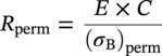
10.10.3 Installation Condition
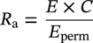
10.10.4 In-Service Condition
10.10.4.1 Pipeline Located Offshore


10.11 Pipeline Design for External Pressure
10.11.1 Buried Installation
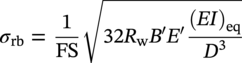
10.11.1.1 Check for Buckling
10.11.2 Above-Ground or Unburied Installation
10.11.2.1 Collapse Criterion

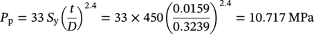
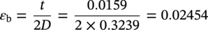
10.11.2.2 Propagation Criterion
10.12 Check for Hydrotest Conditions
10.13 Summary
Appendix 10.A.1 Case Study
Determination of Pipe Diameter
Wall Thickness Design


Description
Value
Unit
Material designation
API-5L-X65
–
Material SMYS
450
MPa
Material SMTS
535
MPa
Steel density
7850
kg/m3
Young’s modulus
207
GPa
Poisson’s ratio
0.3
–
Shear modulus
80000
MPa
Coefficient of thermal expansion
0.00001125
1/°C
Design factor (F)
0.72
–
Joint factor (E)
1
–
Corrosion allowance, (tcorr)
3
mm
Property
Rigid pipeline
Nominal diameter
12 in.
Outer diameter (mm)
323.9
Roughness (mm)
0.04572
Item
Offshore Gas Export Pipeline
Design pressure (barg)
238
Operating pressure (barg)
207
Design temperature (°C)
70
Operating Temperature (°C)
50
Length (km)
58
Normal operating flow rate (MMSCFD)
120


Determination of Components of Stress
Hoop Stress
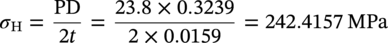
Thin-Walled Pipeline
Compressive Hoop Stress


Longitudinal Stress
Restrained Longitudinal Stress

Longitudinal Stress due to Internal Pressure


Longitudinal Stress due to Thermal Expansion


Bending Stress


Total Longitudinal Stress for the Restrained Section


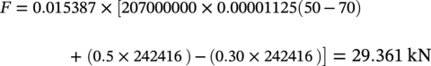
Axial Compressive Force


Axial compressive force


Unrestrained Longitudinal Stress

Longitudinal Stress due to Internal Pressure


Bending Stress


Total Longitudinal Stress for the Unrestrained Section


Equivalent Stress


Limit of Calculated Stress


Allowable Longitudinal Stress
Restrained Section


Unrestrained Section


Allowable Hoop Stress


Allowable Equivalent Stress


Flexibility Analysis

Displacement Strain


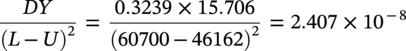
Flexibility Check


External Pressure check
Collapse Criterion
Yield Pressure and Collapse

Elastic Collapse Pressure


Collapse Pressure


Propagation Criterion


Bending Buckling Check


Conclusion
References
Stress-Based Design of Pipelines
(10.1)
(10.2)
(10.3)

(10.6)
(10.7)

(10.9)
(10.10)
(10.11)
(10.12)
(10.13)
(10.14)


(10.17)
(10.18)
(10.20)
(10.21)
(10.22)
(10.23)
(10.24)

(10.27)
(10.28)
(10.29)
(10.30)
(10.31)

(10.33)
(10.34)
(10.35)
(10.36)
(10.37)
(10.38)
(10.39)
(10.40)
(10.42)
(10.44)

(10.46)
(10.47)
(10.48)
(10.49)
(10.50)
(10.51)
(10.52)
(10.53)
(10.54)
(10.55)
(10.56)
(10.57)
(10.58)
(10.59)
(10.62)

(10.64)
(10.65)
(10.66)
(10.67)
(10.68)
(10.69)
(10.70)
(10.71)
(10.72)
(10.73)
(10.74)
(10.75)
(10.76)
(10.77)
(10.78)
(10.79)
(10.80)
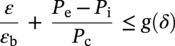
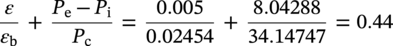
(10.81)
