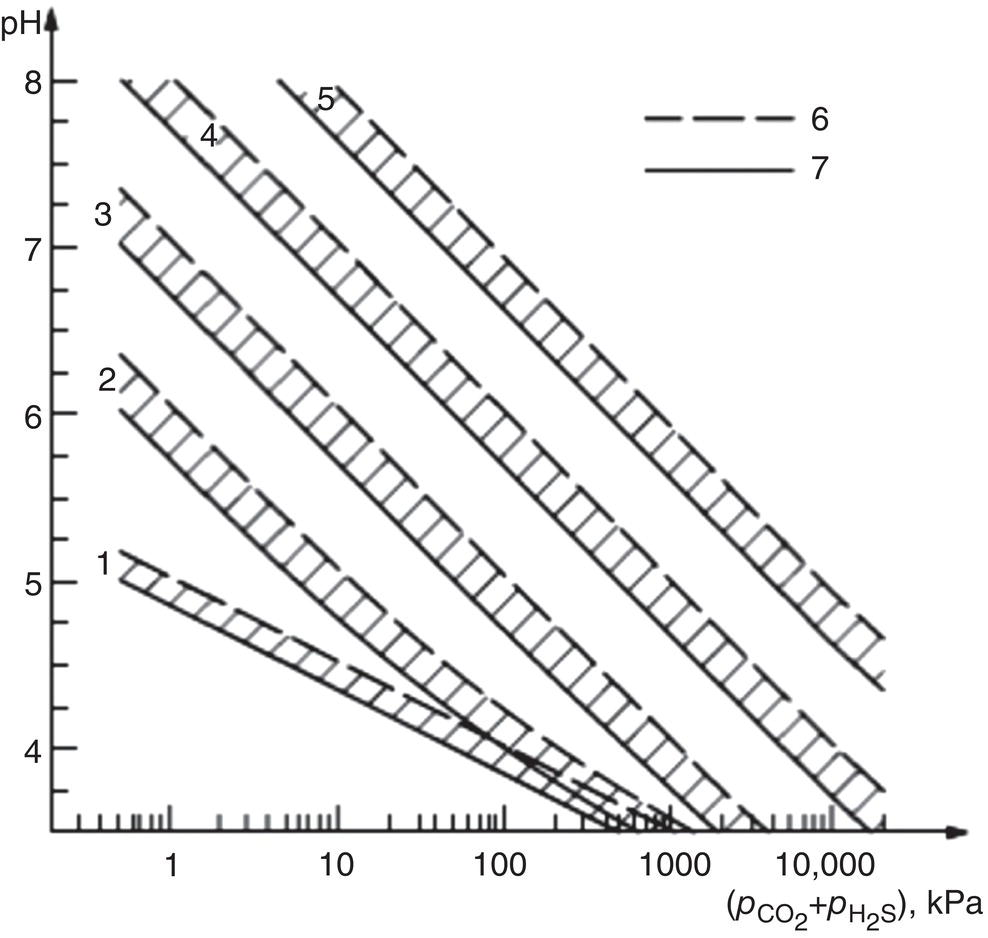
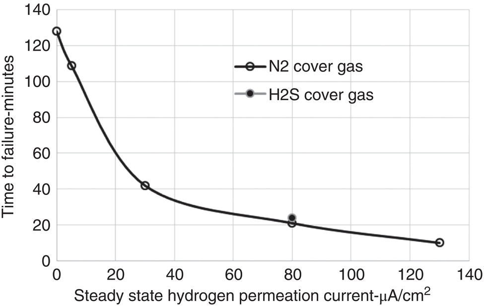
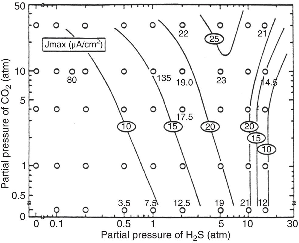
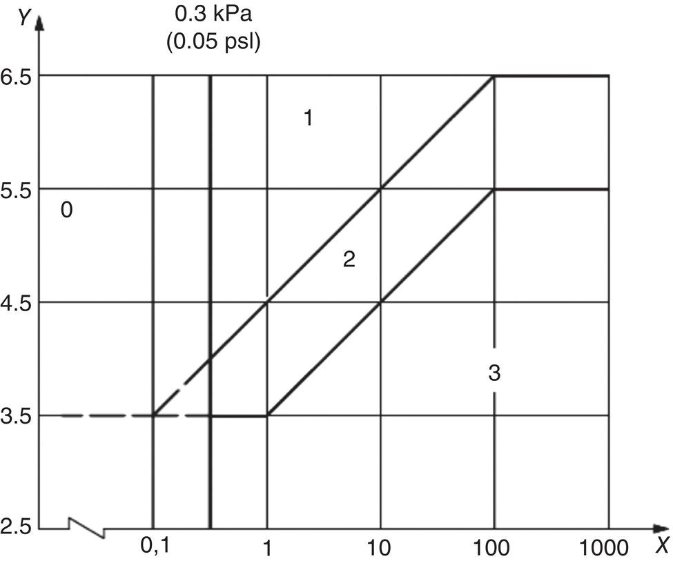
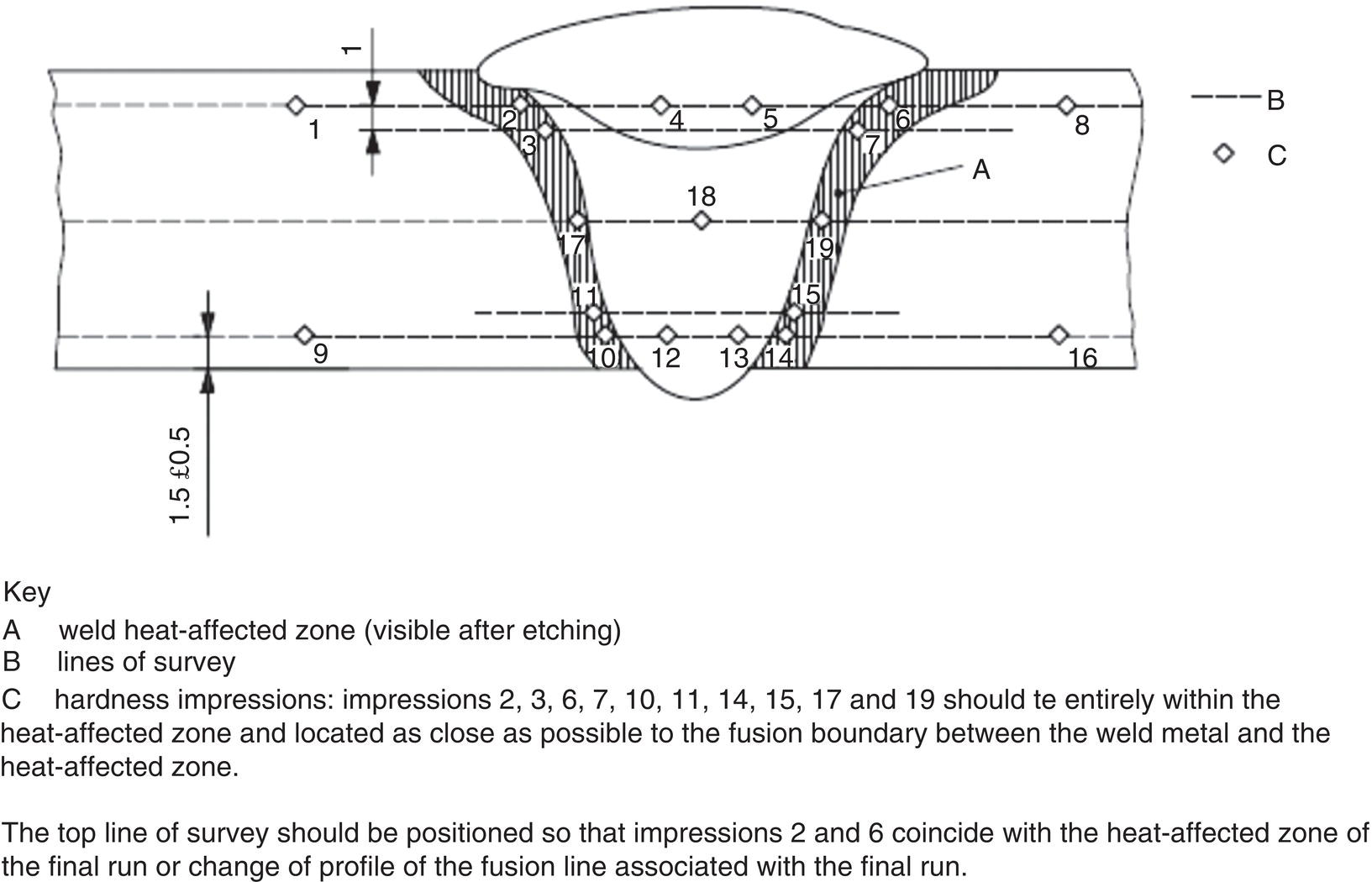
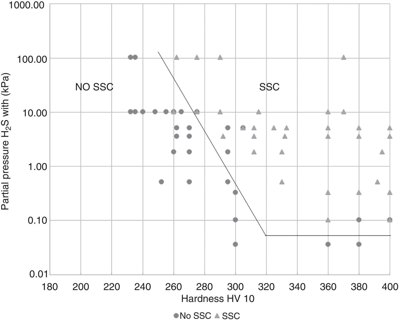
Russell D. Kane iCorrosion LLC, Houston, TX, USA Sulfide stress cracking (SSC) is just one of several forms of hydrogen-related deterioration that can result from exposure of pipelines, facility piping and equipment, and oil country tubulars to sour (wet H2S) service conditions. These are environments that involve exposure to aqueous environments containing hydrogen sulfide (H2S) as found in oil and gas production, gas and chemical processing, and petroleum refining. As a result of this multiplicity of sour cracking mechanisms, it is critical to understand the differences between SSC and the other forms of wet H2S cracking. While the parameters that control all wet H2S cracking mechanisms are generally the same, the influence of specific environmental and metallurgical parameters may vary depending on the cracking mechanisms under consideration. SSC is a particularly insidious form of wet H2S cracking that can lead to embrittlement with loss of ductility and brittle fracture, formation of multiple propagating crack fronts, and sudden catastrophic failure. Under severe situations with susceptible materials such as high-strength or high-hardness steels, SSC can result in high crack growth rates of between 10−8 and 10−5 mm/sec for low-alloy steels [1], whereas crack growth rate of 10−5 mm/sec was demonstrated for hard welds (>HRC 30) in carbon steel [2]. SSC is a form of hydrogen stress cracking (HSC), also referred to as hydrogen embrittlement cracking (HEC) in the presence of H2S or other reactive sulfur species. It typically occurs in high-strength steels [3] and localized hard zones in the pipe [4], particularly in weldments and the heat-affected zone (HAZ). The proclivity for SSC in the area of the weld results from the fast cooling rates commonly applied in joining of pipelines and the associated metallurgical transformations produced by these cooling rates in the steel. This can be in either the longitudinal or helical seam weld made during manufacturing of the pipe or in the girth (circumferential) welds made during laying and fabricating the pipeline in the field. SSC can also occur in high-strength steels and other materials with ultimate tensile strength and hardness that are in excess of accepted maximum values. This is an important concept in prevention of SSC. While most engineers focus on obtaining materials that meet minimum strength or hardness requirements, the materials that usually result in failure by SSC are those on the maximum end of the specification or beyond, which are often left unchecked. SSC is produced in a susceptible material by the simultaneous action of residual and/or applied tensile stresses and internal hydrogen atoms produced by corrosion. In the case of steel, corrosion generally occurs under acidic conditions (pH < 7) by the sulfide corrosion reactions shown as follows [5]: In sulfide corrosion, FeS is a solid compound that is insoluble in aqueous solutions and commonly precipitates on exposed metal surfaces as a scale. In practice, as shown above, iron sulfide corrosion products are based on FeS but can take other forms such as FeS2, Fe7S8, or Fe8S9 depending on the pH, H2S partial pressure, and oxidizing potential of the environment. As a consequence, sulfide corrosion products can vary in their morphology and the degree of their protectiveness. As also shown in the aforementioned equations, one of the natural by-products of the sulfide corrosion reactions is atomic hydrogen (H0) that forms on the surface of the material at local cathodic sites. Atomic hydrogen is a very small atom (with a diameter just over 1 angstrom) and under the right conditions can be adsorbed onto the metal, where it can readily diffuse even at near room temperature. In most acidic corrosive environments, the vast majority of corrosion-generated atomic hydrogen recombines on the metal surface to form molecular hydrogen gas (H2), which harmlessly bubbles off before it is absorbed into the metal. However, in the presence of sulfur species such as H2S, the kinetics of recombination of atomic hydrogen to molecular hydrogen can be significantly retarded, resulting in increased absorption of atomic hydrogen by the metal. This characteristic of sour environments results because sulfur is a highly effective hydrogen recombination “poison,” which acts similarly to species such as Sn, Pb, Sb, and P, which slow recombination and, thus, increase the efficiency of hydrogen charging into the metal. It is accepted that SSC is a form of HSC in most steels. The role of H2S in this phenomenon is generally considered to be twofold: (1) it increases the rate of corrosion of steel in aqueous solutions through its properties, like CO2 of being an acid gas, where it has the ability to form a weak acid solution when dissolved in water (see Figure 58.1 [6]), and (2) it poisons the hydrogen recombination/evolution reaction, as discussed previously, leading to higher-than-normal levels of hydrogen flux in steel. Consequently, H2S results in an increase in the severity of hydrogen charging and HSC versus that observed in similar acid solutions without H2S. A comprehensive mechanistic SSC study was conducted to specifically identify the mechanism of SSC in steel. Tests were conducted both with and without H2S under conditions of applied potential to produce equivalent hydrogen permeation currents in both environments. As shown in Figure 58.2, susceptibility to SSC was found to be directly related to the amount of hydrogen available, not to the presence or absence of H2S. In an H2S-containing environment, the absorption of atomic hydrogen into the metal is enhanced by the poisoning effect of S-containing species, as indicated previously. Therefore, hydrogen charging conditions of a particular magnitude were produced more readily in the H2S-containing environment [7]. Figure 58.1 Solution pH versus acid gas (H2S + CO2) partial pressure also showing the effect of bicarbonate that is commonly present in the aqueous solution; bicarbonate levels: 1–0 meq/l, 2–0.1 meq/l, 3–1 meq/l, 4–10 meq/l, and 5–100 meg/l; temperature: 6–100 °C; 7–20 °C [6]. (From ©NACE International 2009.) Figure 58.2 HSC susceptibility of C–Cr–Mo low-alloy steel (HRC 32) versus hydrogen permeation current for cathodic charging in solutions purged with nitrogen compared with a solution with H2S purge [7]. (From ©NACE International 1984.) Once in the steel, atomic hydrogen readily diffuses at near-ambient temperatures to sites of high internal stress (i.e., grain boundaries, inclusions, and regions of triaxial stress at internal or surface stress concentrations). In the presence of tensile stress, these locations become sites for embrittlement and the initiation of SSC. As mentioned previously, SSC is one of the many environmental cracking mechanisms that result in pipeline steels exposed to aqueous sour service environments. The other mechanisms are discussed elsewhere in this book and include hydrogen blistering, hydrogen-induced cracking (HIC), stress-oriented hydrogen-induced cracking (SOHIC), and stress corrosion cracking (SCC). Table 58.1 provides a useful comparison of the features of these cracking processes. One of the interesting aspects in the literature on SSC is the reference to two categories of SSC: SSC Type I and Type II, starting in 1979 [8] and more recently reviewed [9]. Type II is the most common form of SSC, and as mentioned previously, herein, it is associated with HSC mechanisms found in the results of laboratory studies and field performance. Failures are often associated with transgranular cleavage in moderate-strength steels (550–690 MPa YS; HV 248–300) or intergranular fracture in higher-strength/hardness steels (>690 MPa YS; HV>300). In contrast, as described in the literature [9], Type I SSC involves two stages: the first being the initiation of small blister cracks (HIC) oriented parallel to the applied stress and rolling direction, while the second stage is the linking together of the blister cracks by short segments of transgranular cleavage by an HEC mechanism. This latter type of SSC has been typically observed in lower-strength steels (<550 MPa YS; <HV 248) and is the same as described and defined in Table 58.1 as SOHIC. As can be seen from this description, it is a hybrid mechanism involving both HIC (due to hydrogen pressure build up) and SCC (HSC embrittlement process) in plate steels. It is important to realize that it can also be observed in pipes made from rolled plate, particularly if high residual tensile stress or mechanical stresses co-exist with severe service conditions of high hydrogen charging. Table 58.1 Forms of Environmental Cracking in Aqueous Sour (wet H2S) Service One of the premises on which the occurrence of SSC is based is the requirement for the presence of a conductive electrolyte that can sustain electrochemical corrosion reactions. In many cases, one of two conditions prevail in oil and gas environment service: (1) there is an oil wetting condition, whereby water is excluded from the metal surface or (2) water is contained totally in the vapor phase with no liquid (free) water present in the system for the temperature and pressure that exist. Under these two conditions, there is effectively no corrosion and, thus, no possibility of sulfide corrosion or SSC. In some systems (e.g., highly processed hydrocarbon streams), where the environment is precisely controlled, the aforementioned conditions may allow the use of metals and alloys that would normally be at risk of SSC. However, if conditions are more variable and can change, leading to a reversal in the water wetting tendencies on the metal surface from condensation or varying ratios of water and hydrocarbons, it is important to have selected materials that can handle this situation without suffering the ill effects of SSC. In most service environments involving exposure to H2S in the presence of free liquid water, tendencies of pipeline steels toward SSC generally increase with decreasing pH of the aqueous environment between pH 6.5 and 3. The reason for this behavior is the increased availability of hydrogen ions in aqueous media with lower pH values. It has also been observed that SSC of pipeline steels increases with increasing H2S partial pressure (to a point), a situation that results in pH decrease, which increases the hydrogen flux into the steel and, thus, promotes SSC. High CO2 partial pressure in combination with H2S also helps decrease the pH of the aqueous environment that further increases hydrogen ion availability and the associated hydrogen flux (see Figure 58.3) [10]. Figure 58.3 Peak hydrogen permeation rate (Jmax) values indicated for various conditions of H2S and CO2 partial pressures (in synthetic seawater) [10]. Note: 1 atm = 102 kPa. (From ©NACE International 1996.) As also shown in Figure 58.3, at still higher H2S partial pressures, hydrogen permeation rates can actually decrease from the peak levels seen at lower H2S partial pressures. This effect results in cases where a more stable sulfide film is formed on the steel surface, which reduces the higher hydrogen charging rates observed at lower H2S partial pressures. Therefore, it is important to assess not just H2S partial pressure, but it should be reviewed in combination with other variables. Standard laboratory tests have been developed for SSC, which evaluate materials for cracking in solutions adjusted to pH values in the range of 3–5.5 with buffering agents such as bicarbonate or acetate. While many tests are run at ambient pressure with 15 psia H2S partial pressure, H2S partial pressures in tests are now routinely varied from 0.1 to over 100 kPa to simulate intended service conditions. For more information on testing for SSC, see NACE1 MR0175/ISO 15156 Part 2 [6] and NACE TM0177 methods A—D [11]. Figure 58.4 shows commonly encountered sour service conditions, as depicted in NACE MR0175/ISO15156 Part 2. This figure is commonly known as the “H2S serviceability diagram” and demonstrates the strong relationship between pH and H2S partial pressure when assessing SSC in service conditions, with region 3 being more severe than region 2, which in turn is more severe than regions 1 and 0. To evaluate resistance of metals to SSC with laboratory tests, this industry standard requires applied tensile stress values in the range of 80–100% Actual Yield Strength (AYS) using uniaxial tension specimens, C-rings, or four-point bend specimens. Commonly used solutions are the standard NACE TM0177 Solution A (5% NaCl; 0.5% acetic acid saturated with H2S) at a nominal pH of 3 or a simulated service environment of 5% NaCl + 0.4% CH3COONa with the pH adjusted between 3.5 and 5.5 to the required value from service conditions. Figure 58.4 H2S serviceability diagram (pH versus H2S partial pressure in kPa) shows regions of environmental severity with respect to the SSC of carbon and low-alloy steels; regions 0–3 show generally increasing severity of SSC [6]. (From ©NACE International 2009.) Hydrogen permeation in steels is a highly temperature-dependent phenomenon and, as such, so are SSC tendencies. As shown in Figure 58.5, SSC susceptibility in steels reaches a maximum (i.e., minimum time to failure) around room temperature (23–25 °C) [12]. This interesting but well-documented trend results from an interplay between the high diffusion rate of atomic hydrogen at room temperature with its ability to still be trapped at sites in the steel where it can concentrate in the metal lattice affected by tensile stress. SSC tends to decrease with both decreasing and increasing temperature. At lower temperatures, production in atomic hydrogen decreases and the mobility of atomic hydrogen decreases, which impedes diffusion. At higher temperatures, thermal energy more easily overcomes the trapping energy for hydrogen where SSC is initiated, thus producing the decreasing SSC susceptibility at elevated temperature. Figure 58.5 Effect of environment temperature on SSC susceptibility in terms of time-to-failure for C—Mn steel. Note: maximum susceptibility at near room temperature (23–25 °C). (Adapted from [12].) The major variable used to predict SSC susceptibility and to mitigate this form of environmental cracking is the material strength as characterized in hardness for steels and most other engineering alloys. Hardness commonly serves as a measure of strength through its correlation with the ultimate tensile strength. Susceptibility to SSC generally increases with hardness, although at times, the actual yield strength of the material may be alternatively specified. For selection of steels for use in sour service conditions, NACE MR0175/ISO15156 Part 2 uses Rockwell B and C scale hardness values (HRB/HRC) for specifying the allowable parent metal conditions for sour service while using Vickers hardness (HV5 or HV10) for indicating acceptable conditions associated with welds and applied overlay materials. For unrestricted use in sour service conditions, steels with a maximum hardness of 22 HRC are generally acceptable so long as they contain <1% Ni as an alloying element and do not have extensive cold working, which is usually limited between 5 and 15% strain depending on the steel and product form. However, it is important to realize that this does not necessarily indicate that these soft steels provide acceptable resistance to hydrogen blistering, HIC, or SOHIC (Type I SSC). Separate considerations for these cracking phenomena are provided in Part 2 of the NACE MR0175/ISO15156 and should be reviewed (also, see Chapter 20 in this book for further information.) Allowance is made for some higher-hardness steels up to 26 HRC, provided that they are heat-treated as tubular components made of Cr—Mo low-alloy steels and quenched and tempered to achieve complete transformation to martensite on quenching. Still higher-hardness steels can be utilized if evaluated under laboratory sour conditions as per the requirements necessary to ballot this material condition into this standard (i.e., data from three commercial heat treatments at maximum hardness with triplicate specimens per heat as discussed in NACE MR0175/ISO15156 Part 2 Annex B). For steel weldments, extensive laboratory tests show that isolated hard zones in parent metal, weld metal, and the HAZ region can be detrimental for SSC resistance [4, 13, 14] and that parent metal composition, metallurgical processing, and selection of weld consumables and procedures should be selected to minimize this problem. As with base metals, welds can be deemed acceptable, provided hardness testing for a welding procedure qualification is carried out; however, the hardness methods used are Vickers HV 10 or HV 5 g methods. Acceptable steel welds are those with a maximum hardness of up to HV 250 for the root and mid-passes, and if the external surface of the pipe is not affected by a sour environment, then a cap pass hardness limit, in some cases, can be up to HV 275. A typical HV hardness test arrangement for a butt weld configuration is shown in Figure 58.6 from NACE MR0175/ISO15156 Part 2 [6]. Alternative arrangements are available for other weld configurations in this standard. This NACE standard also allows the HRC hardness method to be used for welding procedure qualification if the design stress does not exceed two-thirds of specified minimum yield strength (SMYS) and the welding procedure specification includes post-weld heat treatment, requiring the agreement of the equipment user. Extensive laboratory testing has shown the general relationship between H2S partial pressure and acceptable weld hardness. Figure 58.7 shows that the NACE/ISO HV 250 limit for weldments and base metal is justified based on data from laboratory tests conducted at 15 psia H2S partial pressure [4]. However, this figure also shows that welds with higher hardness values may be serviceable in environments with lower H2S partial pressures, with the hardness limits at 5 kPa being about HV 300 and the limit for HV350 being near 0.5 kPa. However, the present NACE/ISO standard for sour service requires procedure qualification and H2S testing for establishing hardness/H2S limits for conditions such as these that are not currently in this standard. Carbon and low-alloy steels subjected to cold deforming by rolling, cold forging, or other manufacturing processes that result in permanent strains >5% are commonly thermally stress-relieved with a minimum temperature of 595 °C when a final maximum hardness of 22 HRC or HV250 is obtained. However, based on service experience, there are exceptions, with some cold-worked line pipe fittings acceptable with up to 15% cold strain if the hardness does not exceed 190 Brinell hardness (HBW) [6]. Figure 58.6 Allowable 16-point HV hardness test configuration for butt weld from NACE MR0175/ISO15156 Part 2 [6]. Note: dimensions in millimeters. (From ©NACE International 2009.) Figure 58.7 Relationship between hardness and H2S partial pressure defining serviceability regions for steel weldments showing SSC and no SSC behavior [4]. (From ©NACE International 1981.) Stainless steels and Ni-base alloys offer great potential in engineering design by eliminating the dependence on corrosion inhibitors. However, it must be realized that these materials can, in some cases, act very differently from steels and are subject to a different set of engineering limitations, particularly in sour service conditions involving exposure to aqueous H2S environments. In addition, to justify the cost of corrosion-resistant alloys (CRAs) for many applications, they must also have longer service life and higher strength capabilities in sour service than conventional steels. As such, these materials must be able to overcome the detrimental effects of H2S and CO2 gas, sulfur compounds, and concentrated brine solutions without susceptibility to environmental cracking. To obtain high strength combined with corrosion resistance, there has been increased use of materials containing high levels of chromium, nickel, and molybdenum (see Table 58.2) [5]. There are four classes of CRA materials based on Fe–Ni–Cr–Mo compositions: (1) martensitic stainless steels, (2) duplex stainless steels, (3) high-alloy austenitic stainless steels, and (4) Ni-base alloys. Typically, conventional austenitic stainless (AISI 3XX series) steels do not have adequate strength or resistance from SCC for use in many H2S applications and exhibit chloride SCC at 60 °C and higher. Each classification has different ranges of composition, microstructure, strengthening mechanism, and performance in corrosive production environments. The guidelines for the use of these materials in sour service environments is governed by NACE MR0175/ISO15156 Part 3 [15] that provides material hardness limits and acceptable metallurgical conditions for service conditions based on specific limitations of H2S partial pressure, pH, chloride concentration, and the presence/absence of elemental sulfur. While the first step up in CRA materials are 9–13 Cr alloys, martensitic stainless steels for H2S service have been developed with improved corrosion resistance and mechanical properties compared to the conventional 12–13% Cr grades. For example, high-strength tubular grades of martensitic stainless steels with yield strengths up to 760 MPa have been developed with nominally 13% Cr and are used in the quenched and tempered conditions. These materials contain 13–17% Cr, 4–6% Ni, and 1.5–2% Mo for added resistance to localized corrosion and SSC superior to straight 12–13 Cr alloys. Maximum susceptibility to SSC in martensitic stainless steels typically occurs near room temperature with decreasing cracking susceptibility with increasing service temperature. However, for grades that contain Ni, there is an additional need to consider environmental cracking from SCC usually occurring at local anodic sites and pits. Serviceability limits for these materials are commonly in the range of 1–10 kPa H2S at pH 3.5–4.5, with materials available in the 650–860 MPa minimum yield strength grades at up to HRC 28–30. Selected SSC data for such martensitic stainless steels (with H2S and pH limits) are shown in Figure 58.8 [16]. Table 58.2 Common Corrosion-Resistant Alloys (CRAs) Used in Sour Service [5] Source: ©NACE International 1998. a Most commonly used of the CRA materials listed. Figure 58.8 H2S and pH limits for SSC in a modified 13 Cr (Ni–Mo) alloy for 655 MPa (above) and 863 MPa (below) specified minimum yield strength conditions in 10–20% NaCl solutions, respectively. Note: 1 MPa = 1000 kPa; 100 ksi = 690 MPa). ([16]/with permission of JFE Steel Corporation.) Duplex stainless steels are a mixture of two microstructural constituents, ferrite and austenite. They can be produced in both cast and wrought conditions and typically have 22–25% Cr with yield strengths of 350–620 MPa when in the cast or annealed conditions and up to 900 MPa when cold-worked during processing. These steels derive their mechanical properties and microstructure from a balanced chemical composition that contains alloying additions of Cr, Ni, Mo, (sometimes W), and N. This results in a material with a corrosion resistance comparable to or superior to that of the martensitic stainless, which is also greater than that of conventional austenitic stainless steels. NACE MR0175/ISO15156 Part 3 uses the alloy pitting resistance equivalent number (PREN = Cr + 3.3(Mo + 0.5 W) + 16 N) for evaluating these alloys for serviceability in sour environments, with PREN values in the ranges of 30–40 and 40–45. Duplex stainless steels generally show serviceability with H2S partial pressures in the range 2–20 kPa, which varies with the chloride content of the environment and PREN, cold work used in processing, and hardness of the material up to HRC 36. Maximum susceptibility to environmental cracking in duplex stainless steels typically occurs at intermediate temperatures generally found in the range of 60–120 °C, where both HEC and SSC mechanisms are operable. Highly alloyed stainless and Ni alloys are for H2S service applications, primarily for use as high-strength tubular materials and ancillary pressure control equipment. They can be cold-worked in the range of 30–50% cold reduction to strength levels in the tubular material between 750 and 1000 MPa yield strength. Alternatively, for other components, such as valves and specialized equipment that often require more complex shapes or welding, precipitation-hardened Ni-base alloys, which obtain their strength via aging heat treatments, are available with nearly the same strength levels. Per NACE MR0175/ISO15156 Part 3, high-alloy austenitic stainless steels at up to HRC 35 are serviceable under conditions of 100–690 kPa H2S partial pressure, which varies with PREN and total alloy composition, along with chloride content and maximum service temperatures in the range of 60–171 °C. By comparison, Ni-base alloys vary in the performance based on alloy composition and strength, environmental variable of H2S partial pressure, chloride, and exposure to elemental sulfur. Precipitation-hardened Ni-base alloys with hardness values in the range HRC 35–44 have limits of H2S partial pressure in the range 200–3400 kPa, chlorides up to 180,000 mg/l, and maximum (in some cases) and maximum service temperatures varying from 135 to 232 °C, respectively. By comparison, the cold-worked Ni-based alloys show service limits from 200 to 6900 kPa H2S at temperatures ranging from 132 to 232 °C with unrestricted chloride levels. High-temperature sour service environments, when found in combination with elemental sulfur, appear to accelerate anodic SCC in much the same way that oxidizing agents increase the severity of SCC in nonsulfide-containing environments. The most highly alloyed materials (with minimum level of 14.5% Cr, 52% Ni + Co, and 12% Cr) are utilized for service conditions that include exposure to elemental sulfur in combination with up to 6900 kPa H2S, with some alloys available up to HRC 45. It must be kept in mind that when corrosion-resistant alloys (martensitic, duplex, and austenitic stainless steels and Ni-base alloys) are used for sour service applications in the welded condition or as weld overlays, the limits for SCC may vary from those provided herein based on the parent metal composition and metallurgical condition, along with the weld consumables and procedures used. For such situations, the applicable sections of NACE MR0175/ISO15156 Part 3 need to be consulted for specific advice for appropriate guidelines, qualification, and specification. These H2S serviceability limits may need to be determined through procedure qualification and SSC testing per methods described in this document and the ancillary SSC test methods referenced by it.
58
Sulfide Stress Cracking
58.1 Introduction
58.2 What is Sulfide Stress Cracking?
58.3 Basics of Sulfide Stress Cracking in Pipelines


58.4 Comparison of SSC to Other Sour Cracking Mechanisms
Cracking Mechanism
Phenomenon
Materials
Stress
Method to Prevent
SSC
Embrittlement by atomic hydrogen at areas of high internal or surface tensile stress (e.g., grain boundaries and notches)
Usually associated with high-strength (>550–690 MPa YS) steels or high hardness (>HRC 22) areas; can occur at lower HRC values if cold work is present
Tensile stress required
Limiting YS or HRC; steels with accelerated cooling or QT better than NT or hot-rolled; limit design stress
Blistering
Accumulation of atomic hydrogen at weak internal interfaces (e.g., inclusions) and the formation of hydrogen gas pressure, which inflates blisters
Lower-strength pipeline steels (<550 MPa YS; <HRC 22) with centerline segregation or high impurity levels, resulting in massive sulfide inclusions
No applied stress required
Use of steels with lower impurities (especially sulfur)
HIC
The link-up of small- to moderate-sized internal hydrogen blisters in the form of stepwise blister cracks
Low-strength pipeline steels (<550 MPa YS; <HRC 22) with intermediate sulfur levels especially made with extensive hot rolling
No applied stress required
Use of steels with lower impurities (S < 0.006%; P < 0.015%) with Ca-treatment for sulfide shape control
SOHIC
The linear through thickness array of small blister cracking that links by brittle cleavage under the influence of high applied or residual tensile stress
Low strength and often in low sulfur, HIC-resistant steels (<550 MPa YS; <HRC 22) with low sulfur levels
Usually requires high hydrogen charging conditions and high residual/applied tensile stress; exacerbated by severe notch or weld toe geometries
Use of HIC-resistant steels with ultralow sulfur <0.002 with Ca-treatment (caution not to over Ca-treatment); QT > NT > hot rolled. Reduce stress concentrations and hydrogen charging severity; replace with CRA-clad steel
SCC
Brittle environmental cracks that form and propagate from the action of local anodic sites and tensile stress
In Ni-containing steels in aqueous sour service environments; at higher temperatures, H2S combined with chloride results in SCC in stainless and Ni-base alloys
Tensile stress required
Keep Ni content of steels <1%; alloy stainless materials with sufficient Cr, Ni, Mo, and N for resistance to local corrosion, pitting, and SCC
58.5 Influence of Environmental Variables on SSC
58.5.1 Availability of Liquid Water
58.5.2 pH and H2S Partial Pressure

58.6 Influence of Metallurgical Variables on SSC in Steels
58.7 Use of Corrosion-Resistant Alloys to Resist SSC
Stainless Steels
Nominal Compositions (wt)%
Designation
Fe
Ni
Cr
Mo
N
Other
Comments
Martensitic SS
13Cr
Bal
–
13
–
–
–
Low cost/resists CO2 corrosion
Modified 13Cra
Bal
5.0
13
2.0
–
–
improved corrosion resistance (esp. in H2S) and strength over 13 Cr
15Cr
Bal
1.5
14.5
0.5
–
–
Improved corrosion resistance over 13 Cr
Duplex SS
18Cra
Bal
4.5
18.5
2.5
00.7
–
Lower cost than 22/25 Cr alloy
22Cr
Bal
5.5
22.0
3.0
0.10
–
resists CO2 and low/mod H2S
25Cr
Bal
6.0
25.0
3.5
0.20
W
higher corrosion and SCC resistance than 22 Cr, especially w/added Mo and W
High Alloy Austenitic SS
Alloy 28
Bal
31.0
27.0
3.5
–
–
Higher resistance to CO2, mod H2S and Cr
Alloy 254a
Bal
18.0
20.0
6.0
0.20
–
Low Ni and Cr content but high Mo and N for pitting resistance
Alloy 904a
Bal
25.0
21.0
4.5
–
–
Low Ni and Cr content but high Mo and N for pitting resistance
Alloy 6XNa
Bal
24.0
21.0
6.5
0.20
–
Low Ni and Cr content but high Mo and N for pitting resistance
Nickel-Base Alloys
Nominal Composition (wt)%
Designation
Fe
Ni
Cr
Mo
N
Other
Comments
Cold-Worked
2535a
Bal
38.0
25.0
3.0
–
–
Lower nickel content than 825, higher, and higher pitting resistance
825
Bal
42.0
21.0
3.0
–
–
Good resistance to CO2/high H2S and Cl−/moderate temperature
G-30a
20
Bal
22.0
7.0
–
–
Good resistance to CO2/high H2S and Cl–/high temperature
2550a
20
50.0
25.0
6.0
–
2.5 W
Better resistance than G3 to CO2/high H2S and Cl−
G-50
17
50.0
20.0
9.0
–
–
Better resistance than G3 to CO2/high H2S and Cl−
C-22a
4.0
Bal
21.0
13.5
–
3.0 W
Alternative to C-276 in some environments
C-276
5.5
Bal
15.0
16.0
–
3.5 W
Excellent resistance to CO2/high H2S and Cl−/very high temperature and sulfur
Precipitation-Hardened
925a
Bal
42.0
21.0
3.0
–
2.0 Ti
Lower Ni and cost option to alloy 718
718
Bal
52.0
19.0
3.0
–
1.0 Ti/5.0 Cb
Good resistance to CO2/mod H2S and Cl−
725a
8.0
Bal
21.0
8.0
–
3.4
Better pitting and SCC resistance than 718
625 plusa
5.0
Bal
21.0
8.0
–
1.5 Ti/3.5 Cb
Better pitting and SCC resistance than 718

References
Note