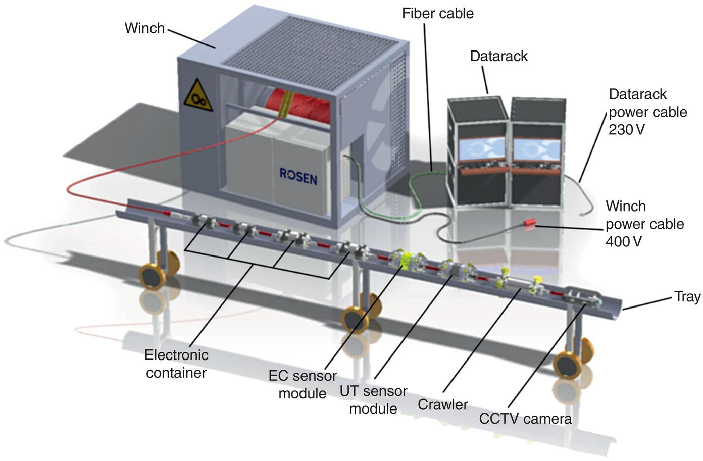
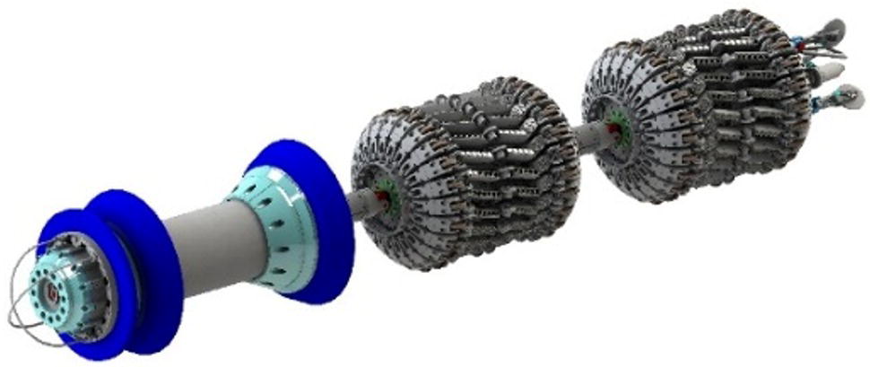
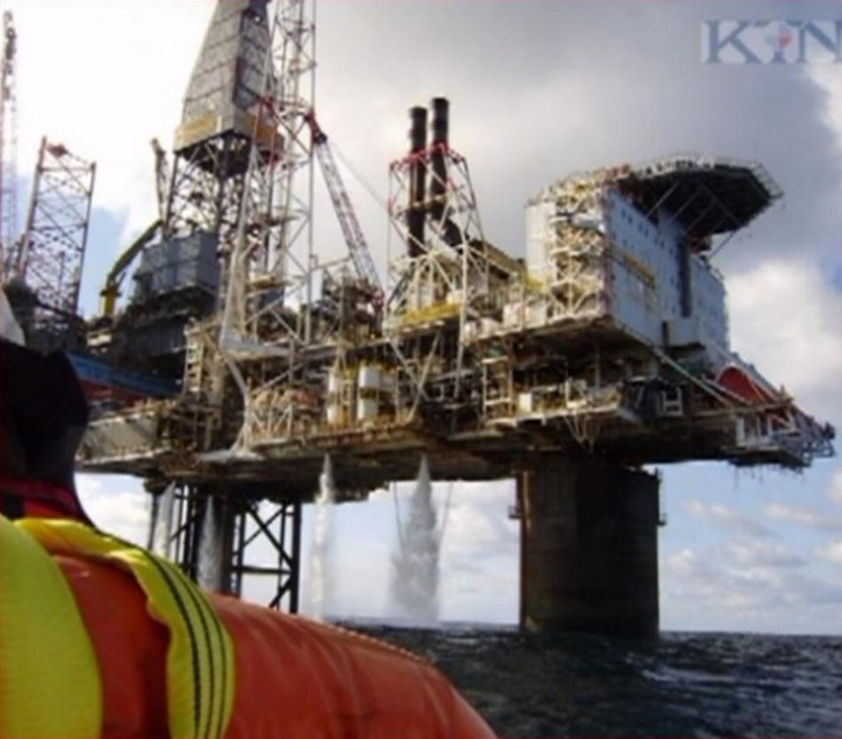
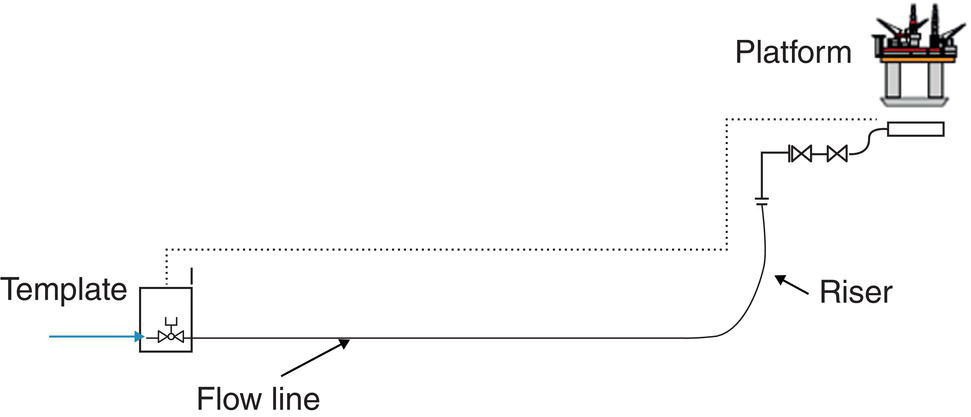
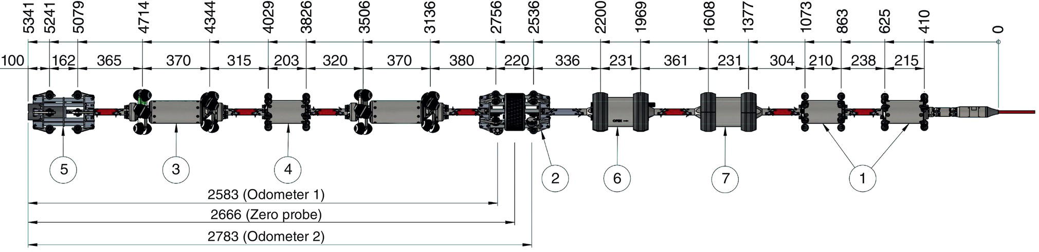
A. Enters1 T.-S. Kristiansen2 and U. Schneider3 1ROSEN Europe B.V., Oldenzaal, The Netherlands 2ROSEN Norway AS, Bergen, Norway 3ROSEN Group, Mannheim, Germany Since the introduction of in-line inspection (ILI) tools more than 50 years ago, there have always been pipelines that were considered unpiggable. Different technologies, including ultrasonic wall thickness and crack measurement (vertical and angular beam pulse echo, time-of-flight diffraction, and phased array), eddy current, and different types of propulsion elements, including bidirectional self-propelled (crawler) and pumped modules, are available for use on specialized tools. The system is capable of quantitatively measuring crack depth and profile, data are collected on the way in and out, and results are visible in real-time. Tethered technologies are used to inspect pipelines with diameters of 6 in. or larger and up to 24 km in length. The unique ability of the system to navigate complex pipeline geometry is explained through a case study of a 10-in. offshore oil riser. Keywords: Unpiggable Pipelines; Tethered Inspection; Offshore Riser; The pipeline network worldwide is aging; therefore, it needs to be maintained and its integrity assessed. For more than 50 years, this has been done with so-called in-line inspection (ILI) tools or inspection pigs for different kinds of defects. However, there have always been pipelines that were considered unpiggable. Typically, it is a combination of various circumstances relating to pipeline design, operating conditions, and/or characteristics of the medium that prevents a successful ILI using traditional methods. Different types of technologies, including ultrasonic wall thickness (vertical beam pulse echo) and crack measurement (angular beam pulse echo, time-of-flight diffraction, and phased array), eddy current, as well as different types of propulsion elements, including bidirectional self-propelled (crawlers/tractors) and pumped modules, are available for specialized ILI tools. The system is quantitatively capable of measuring geometry, wall thickness/corrosion, crack depth, and crack profile. Data are collected on the way in and out, and results are visible in real-time. Tethered technologies are capable of inspecting pipelines with a diameter of 6 in. or larger. Pipelines up to 12 km in length have been successfully inspected, and inspection of those with distances up to 24 km are possible. Although tethered ultrasonic measurement (TUM) is typically designed for a special project, the typical composition (Figure 31.1) consists of the following: The main differences between a conventional, free-swimming, unidirectional pumped tool (Figure 31.2) and a tethered bidirectional self-propelled tool (Figure 31.3) are the following: Conventional tools go from A to B and get their driving pressure from their cups and/or discs. The sensor carrier is typically flexible. The TUM tool has no cups or discs and many bypasses. It is extremely lightweight, made of titanium, and runs on wheels. The sensor carrier is a stiff ring. The main purpose of the lightweight tool and wheels is to require very little pulling force and almost no friction in order to be able to inspect longer sections, even through many bends. Figure 31.1 Principle of tethered ultrasonic measurement (TUM). (Reproduced from Ref. [1] with permission of EITEP Institute.) Figure 31.2 Conventional ILI tool. (Ref. [1]/with permission of EITEP Institute.) Another difference from conventional tools is use of winches. Successfully completed runs so far went up to 12 km, but runs up to 24 km are possible depending on the number of bends, bend angles, and pipeline configuration (two- or three-dimensional). Figure 31.3 TUM module. (Ref. [1]/with permission of EITEP Institute.) A series of different crawlers and tractors are available for all diameters and forces up to 750 kg of pulling force each; crawlers and tractors of 6 to 48 in. diameter have been manufactured already and those up to 56 in. can easily be prepared. Figures 31.4–31.6 show a typical challenging pipeline—a riser from platform to subsea—which makes the use of a conventional tool that is extremely expensive because the pig receiver would need to be fabricated and installed subsea. Thus, the pipeline inspection would have to be operated with the assistance of a diving support vessel. A risk assessment concluded that the riser to be inspected was a high-risk operation. An inspection solution needed to be developed. It is much easier and more cost-effective to use the tethered self-propelled bidirectional UT tool, which can inspect geometry, wall thickness, and cracks in one run. This tool can be launched and received from a trap at that platform without the need for a diving support vessel and a subsea trap, making it the right choice for this project. The special challenge with this pipeline was the number of bends (and the total angle). Because every additional bend adds friction, the number and angle of bends in most cases are limiting factors for a tethered inspection. Figure 31.4 Offshore platform. (Ref. [1]/with permission of EITEP Institute.) Figure 31.5 Platform with the riser. (Ref. [1]/with permission of EITEP Institute.) Initially, the target was to inspect a section of nearly 200 m, including up to eleven 90° bends and two 2.4° vertical miter bends. For the riser inspection, the main issue was the pullback force of the tool. In case a tethered crawler tool loses power, the tool needs to be pulled back using the winch. The pulling force of the 10-in. tractors is approximately 200 kg each and is not the limiting factor for the inspection of this riser. In order to confirm the feasibility of passage and retrieval through one 90°-bend, a tool was developed and tested successfully in a test loop in Bergen, Norway. The main purpose of the tests was to demonstrate that the tool could be retrieved using the umbilical. Based on the friction profile from the test loop (the pullback forces as a function of tool position in the loop), the pullback forces were correlated with the riser configuration. The required pullback forces were quantified, in case the tool lost power within the riser system. Figure 31.6 Challenging offshore riser with many bends. (Ref. [1]/with permission of EITEP Institute.) After extensive testing, the inspection with UT wall thickness and TOFD for cracks was conducted successfully, with good results. A few years later, for reinspection, the challenge was to crawl further (+130 m; total length >300 m) into the horizontal subsea section, which included another six bends. Pipeline details: Again, crawler testing was done prior to mobilizing in Bergen, including measuring the following: Finally, the equipment and team were mobilized, and a temporary trap was installed with a stuffing box (cable penetration) as well as guide wheels for routing the cable. Further, the winch was placed, the computer equipment was positioned in a location, and the function tests were done. A special stuffing box with a cable feeder and hydraulic seal-closing clamp was designed, manufactured and tested to 100 bars (10 MPa) for these inspections. The cable feeder was designed to reduce cable friction at the stuffing box location, and the hydraulic seal closing clamp was made in order to make the stuffing box “water tight” in case of a sudden pressure surge in the pipeline. The winch used had a 1.2-km umbilical with a breaking load of 2000 kg and a normal pulling force of 1000 kg. The winch was certified for ATEX Zone 2. Two different tool train configurations were used: In order to see a blocked pipeline (closed valve or similar), a sonar was mounted in the front of the tool. Sonar is used as a method for locating objects in space and underwater by means of emitted sound pulses. Two electrical crawlers were run in a tandem configuration. This configuration was designed for increased pulling force to ensure that the tool could negotiate difficult-to-pass pipeline components, such as slippery valves and Ts. An ultrasonic sensor carrier with 160 UT probes was used, along with two odometers measuring the distance traveled and tool velocity. The movement of the odometers triggers the data collection. Therefore, if the tool train stands still, data are not collected. The inspection can be carried out with only one working odometer. A purpose-made scanner equipped with TOFD probes is used to scan any features. Straight-beam PE probes are installed to position the scanner correctly against girth welds to be assessed. When deploying TOFD sensors at corroded features in the parent material, the TUM-WT tool position is used to determine the correct positioning of the TOFD tool. Finally, the pipeline was shut down, and the tool was passed into the pipeline for approximately 300 m, collecting wall thickness data on the forward and return run. After that, the tool was modified from a TUM-Sonar to a TUM-TOFD configuration, tested, and launched again. During the run, many pull and pullback force measurements were done along a preselected distance in order to calculate the friction coefficient of the riser and to guarantee a return was possible even in the worst case. During testing and the actual inspection activities, two operators operated the umbilical winch, tool train, umbilical, etc., and two operators in the location were in charge of operating the computers: propulsion and UT/Sonar. During the second run, the tool stopped at some preselected girth welds to make full circumferential TOFD scans. Scans were also conducted in any areas that appeared conspicuous (such as splash zones) from the wall thickness data collected during the first run. After presenting a site report, which typically shows the most severe defects detected, the equipment and the team were demobilized, and the detailed analysis was started. The data evaluation team worked with four data sets for wall thickness (two forward and two return runs) and two data sets for TOFD crack analysis. The full length and circumference of the targeted pipe section were successfully inspected, and the collected data were of very good quality, meeting the required specifications. As a result of a risk assessment of some offshore unpiggable pipelines, the riser had been categorized as “high risk” for the operation. Therefore, an inspection solution needed to be developed. Extensive testing (especially crawler testing) in a test loop was performed prior to the first inspection. Figure 31.7 Inspection tool train—TUM-WT-Sonar; the tool with WT + TOFD had one additional module. From left to right: 5) sonar module, 3) crawler, 4) power supply, without number) second crawler, 2) sensor carrier for wall thickness measurement, 6) front end electronic, 7) data module, and 1) 2 modules for voltage transformation and cable connection. Tool moves from right to left; the front module is on the left. (Ref. [1]/with permission of EITEP Institute.) The successful inspection was repeated some years later with a longer inspection distance and more bends to pass (record of 1188° total)—17 bends in total. The benefits of the tethered solution were as follows: Highly accurate UT and TOFD data allowed for a fitness-for-purpose evaluation, specific decision-making, and the continued safe operation of the riser.
31
Tethered Inspection of the Riser System for Wall Thickness and Cracks
Abstract
31.1 Introduction
31.2 Tethered Tool Principle

31.3 Case Study: 10-In. Rigid Offshore Oil Riser Inspection for Wall Thickness and Cracks
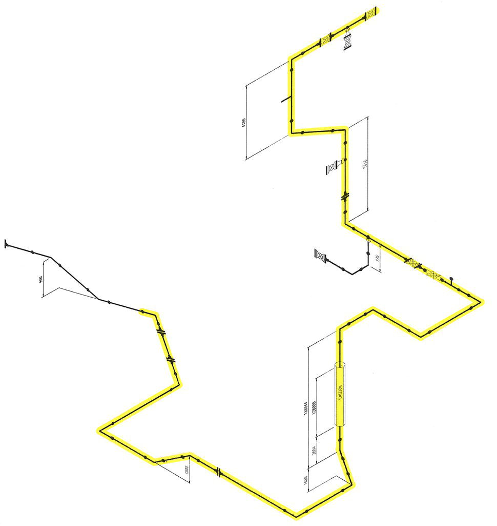
31.4 The Reinspection Project
31.5 Summary and Benefits
Reference