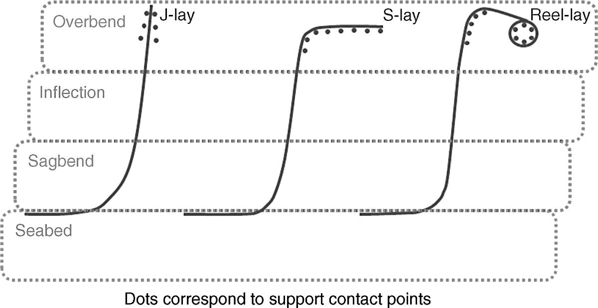
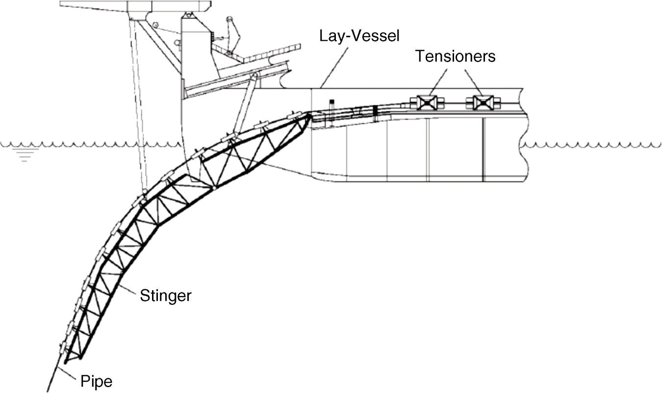
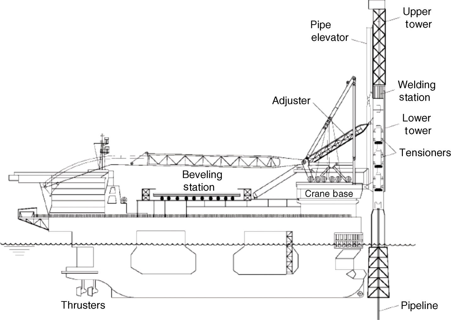
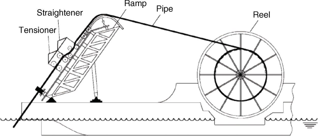
Robert O’Grady Wood Group Kenny, Galway, Ireland The installation of offshore pipelines represents a considerable challenge that requires installation methods and procedures that are both safe and cost efficient. Successfully achieving these objectives requires an understanding of the effects of installation on pipeline integrity. This chapter discusses the following topics as a way of developing such an understanding: The discussion of these topics is covered in this chapter. The primary methods of rigid pipeline installation include S-lay, J-lay, and Reel-lay. Each of these methods has its own unique aspects from a pipe behavior point of view and so they are individually outlined here in turn, but first, a general discussion on installation loading and failure modes is worthwhile. Note that other less adopted installation methods exist as well, such as tow out, but these have been omitted here for conciseness. Regardless of the method used, there are generally four different regions of loading behavior through which a pipe joint passes during installation. Figure 22.1 highlights the four loading regions for the primary installation methods. Typically, these regions are aligned in the same vertical plane and the first of them is known as the overbend. The overbend represents the upper part of the suspended pipeline, which interacts with the installation vessel through various support and tensioning systems. This region encounters some level of hogging curvature, the magnitude of which depends on the installation method in question. For example, with S-lay there is typically a relatively high level of overbend curvature while for J-lay there is often only a small amount of such curvature. In fact, strictly speaking J-lay can sometimes be viewed as not having an overbend region at all, but for the sake of consistency a J-lay overbend is included in the discussion here. Below the overbend, there is an inflection region where the pipeline tends to straighten out before its curvature is reversed to sagging toward the bottom touchdown region of the pipeline, known as the sag bend. Once the pipeline passes through the sag bend and touches down, it then reaches the final seabed region where once again it straightens out. It is worth highlighting that the relative size, or length, of the respective loading regions varies depending on the installation method, the water depth in question and also the procedure being performed. For example, in shallow water the length of the inflection region shrinks considerably to the point that there can be an almost immediate transition between the overbend and sag bend. Also, as mentioned already, for J-lay the overbend region can shrink to zero length due to the lack of hogging curvature. In addition to water pressure the two main types of loads encountered during installation are axial loads and in-plane bending moments. The magnitudes and directions of these two load types can vary across the different loading regions. For example, the in-plane bending moments are relatively insignificant in the inflection and seabed regions, which tend to be dominated by axial loads. On the contrary, in-plane bending moments are often dominant in the overbend and sag bend regions. Out-of-plane bending moments sometimes occur as well, particularly when a pipeline is installed along a tightly curved route or when environmental loadings approach the pipeline and vessel in a somewhat lateral direction. In some more extreme circumstances other additional load types, such as shear point loads and distributed torque moments, also come into play and can influence pipeline behavior. Such circumstances are described later. Given the primary load types discussed earlier, the governing failure mode for rigid pipelines during installation is typically local buckling with subsequent buckle propagation, and so special attention needs to be given to this during the analysis and design phase of an installation project. This is particularly applicable to the bending-dominated areas of the overbend and sag bend. With dynamic movements of the vessel and pipeline, under environmental conditions, cyclic stresses also develop along the various regions and this then equates to fatigue damage. While fatigue damage represents another possible failure mode during installation, particularly in severe environments and deeper water where there is longer exposure to damage, it is more of a concern from the point of view of maintaining integrity over the lifetime of a pipeline. This means that fatigue damage during installation needs to be kept below a certain allowable threshold so as to provide an adequate contingency for the fatigue damage that will inevitably be accumulated over the operational life span of a pipeline. Both fatigue damage and local buckling are discussed further in subsequent sections. The S-lay method, as illustrated by Figure 22.1, involves welding pipe joints back-to-back to form an S-shaped line that runs from the installation vessel over a supporting stinger structure, down through the water column, and onto the seabed. Figure 22.1 Elevation views of primary installation methods with loading regions highlighted. On the installation vessel, the welding is done along a linear line of roller supports, known as the firing line, and the pipeline is held in place by a set of tensioners gripping the pipeline at intermittent points along the line. The vessel stinger is a truss-type structure fitted with spaced roller beds that both guide and support a pipeline as it leaves the vessel during installation. The configuration of the roller beds is typically curved in profile in order to allow for the pipeline to gradually bend downward as it enters the water column, thus minimizing the stress and strain in the pipe. Figure 22.2 shows a typical S-lay vessel spread. The stinger can be either a fully rigid structure with a fixed rotation about a hinge point on the vessel, or else it can be divided into a series of individual sections connected with multiple flexible hinges that allow for a certain level of rotation independent of the vessel. In the latter multihinged case, the stinger sections usually have some level of inherent buoyancy so as to provide static uplift to the pipeline in shallow water scenarios where the departure angle of the pipeline, as it leaves the vessel, needs to be kept relatively small in order to minimize bending in the sag bend. The flexibility of the hinged sections also minimizes bending in the overbend during dynamic upward movements of the vessel under wave loading. This overall configuration is known as a floating stinger, and, as alluded to already, it is of use in shallow water scenarios. The fully rigid stinger case mentioned previously is most applicable to moderate and deepwater scenarios where the departure angle can be much larger without jeopardizing the integrity of the sag bend. The key benefit of S-lay is that it achieves a relatively high level of productivity with few restrictions on pipe diameter or wall thickness. Such productivity levels are possible due to the fact that the pipe joint welding is done simultaneously across multiple stations along the firing line, which typically runs the length of the installation vessel. Figure 22.2 Typical S-lay vessel spread. (Reproduced from [1]/with permission from Elsevier.) There is, however, a drawback to S-lay and that is the level of axial tension experienced by the pipeline and tensioner system on the vessel grows considerably with deeper water where the length of the suspended pipeline in the inflection region inevitably increases. This then means that the radius of curvature for the stinger must be reduced in order to keep the suspended length, and so the tension, within necessary limits. This application of S-lay to deeper water is known as steep S-lay, given the almost vertical orientation of the pipeline as it leaves the stinger. Steep S-lay can in its own right be defined as another installation method, but for conciseness this is not done here. Such a reduction in stinger radius during steep S-lay leads to direct increases in in-plane bending along the overbend. Larger bending in combination with the significant axial tension means that there is a greater potential for plastic strains developing along the pipeline over the stinger. This is because the bending moment capacity of pipe joints decreases in tandem with increases in tension. Also, because of the intermittent support of the spaced stinger roller beds, the larger tension causes concentrations of strain on the beds themselves. To further elaborate on the aforementioned, under significant tension, the pipe tends to straighten in the spans between roller beds, which in turn results in a higher curvature at the beds themselves so as to compensate for any straightening and to allow the pipeline to still follow the stinger. This concentration behavior also leads to increased shear loads from the roller beds, which if large enough induce permanent ovalization of the pipe cross-section. The overall net result of these tension effects is that pipelines often experience some level of plastic deformation as they pass over an S-lay stinger during deep water installation. This plastic deformation presents itself physically as residual hogging curvature and possibly ovalization. The reversal of curvature in the sag bend region must overcome any residual hogging curvature from the overbend through both bending and twisting of the pipeline. This twisting behavior corresponds to a rotation about the pipeline longitudinal axis and is known as pipe roll. Such a roll inevitably causes torque moments to build up and along the pipeline during installation. The level of pipe roll is dependent on a number of parameters, but one of the primary contributors is the magnitude of the residual curvature itself with larger curvature values generally resulting in greater levels of roll. From a purely operational point of view, pipe roll is undesirable as it causes misalignment issues when installing in-line structures, such as tee pieces, along a particular pipeline. However, pipe roll, and indeed residual curvature, may also have implications for the bending response in the regions below the overbend. These implications are not well understood but could indeed prove influential for future ultra-deep installation scenarios. More discussion on this topic is provided in a later section. The J-lay method, as illustrated by Figure 22.1, also involves welding pipe joints back-to-back, but in this case the overall line forms a J-shaped profile starting at a steep angled tower on the installation vessel, down through the water column, and onto the seabed. The J-lay tower is made up of a series of tensioners, clamps, and o-shaped supports whose diameters increase as the pipeline approaches the bottom of the tower so as to form a bell mouth effect that allows the pipe a controlled amount of free movement under dynamic conditions, thus preventing strain concentrations at the clamps further up the tower. Figure 22.3 shows a typical J-lay spread on an installation vessel. Given the relatively steep departure angle of the pipeline as it exits the tower, J-lay is only really applicable to deeper water scenarios where the sag bend is somewhat below the vessel. Compared with S-lay, J-lay typically requires smaller axial tension loads to support the suspended pipeline in a given water depth and since the orientation of the load is almost vertical the vessel itself requires less thrust to hold position. In addition, with J-lay it is sometimes possible to simply support the pipeline using collars and a hang off table rather than using more complex tensioner systems. All of these aspects represent particular benefits of J-lay over S-lay. In terms of pipeline deformation, J-lay imparts negligible overbend curvature when compared to S-lay, and so the likelihood of continuous plastic strains developing is small. That being said, depending on the level of dynamic movement of the pipeline and vessel, due to environmental conditions, there is still the potential for local buckling, particularly in the sag bend, but also in the overbend. Fatigue damage is still a concern with J-lay as well. The main drawback of J-lay is that because the tower is orientated almost vertically then it can only be of a finite length and so is usually only long enough for a small number of welding stations. This in turn means the productivity levels of J-lay are somewhat less than those of S-lay, meaning over time it can become a more expensive installation method. For this reason, J-lay is often deployed for the installation of shorter infield flow lines, whereas S-lay is used for the installation of longer export trunk lines. Figure 22.3 Typical J-lay vessel spread. (Reproduced from [1]/with permission from Elsevier.) The Reel-lay method fundamentally differs from both S-lay and J-lay in that the pipeline welding is done onshore in a fabrication yard prior to the installation project and then entire lengths of the pipeline are wounded, or reeled, onto a carrousel, or reel, that is eventually deployed to the installation vessel. Once on the installation vessel the pipeline is reeled off the carrousel as it passes through a set of straighteners, tensioners, and ramp supports before entering the water and adopting a sag bend catenary down to the seabed. Figures 22.1 and 22.4 illustrate this reeling-off process. Since pipelines are reeled off a carrousel at a relatively high speed, Reel-lay represents a very productive installation method. That being said, there are restrictions on the diameter and wall thickness of pipes that can be safely reeled onto a carousel without jeopardizing integrity. Also, due to the relatively small radius of the carrousels there is inevitably some level of plastic deformation imparted to a pipeline during the reeling-on process and while the straighteners on the vessel are intended to remove residual curvature, they often cannot eradicate all of the curvature before the pipe enters the water. As with S-lay, such residual curvature has implications for the regions below the overbend in terms of pipe roll and so on. Figure 22.4 Typical reel-lay vessel spread. (Reproduced from [1] with permission from Elsevier.) Ovalization can also occur during the reeling process in addition to local buckling, which is itself a potential problem when the pipeline is deployed from the vessel during installation, as is the case with the other installation methods. The reeling on process limits the application of relatively thick coatings as well, given the likelihood of crushing the coatings through excessive bending. Given the speed at which a pipeline is installed during Reel-lay, the associated fatigue damage tends to be relatively minor when compared with the other installation methods. However, the relative velocity at which the Reel-lay installation vessel moves introduces additional behavior in terms of increased hydrodynamic loads acting on the pipeline. The factors governing the installation of a particular pipeline are a mixture of vessel-specific restrictions and pipeline integrity criteria. These factors are discussed in the following sections. Any given installation vessel has an inherent set of restrictions that must be adhered to during an installation project otherwise potential damage could be done to both the vessel and the pipeline. Sample vessel restrictions include Adherence to such restrictions is not only dependent on the static behavior of the suspended pipeline but also on the dynamic response of the pipeline, and indeed the vessel, to environmental conditions such as waves and currents. Ensuring adherence means designing suitably safe installation procedures covering the entire installation project. The design process is done prior to going offshore and involves predicting both static and dynamic behavior for a variety of procedures and a limiting set of environmental conditions. This generally requires the use of some numerical analysis method, such as finite element analysis. Recommended installation analysis and design methodologies are discussed in a later section, but at this stage, it is worth noting that the main deliverables from the analysis and design phase are a set of reports and tables that are used as a reference by vessel personnel to safely plan and monitor the installation procedures offshore. The primary integrity criterion during installation is the prevention of pipeline failure. As described in a previous section, the governing failure mode during installation is usually local buckling of the pipeline with possible subsequent buckle propagation. Prevention of such a failure again requires a suitable analysis and design process that covers the key aspects of the installation campaign both statically and dynamically. The design aspect is guided by checks outlined in industry-accepted standards and recommended practices such as those developed by Det Norske Veritas or the American Petroleum Institute. Local buckling is most likely to occur in either the overbend or sag bend regions. Typically, the overbend represents a safer area as it encounters relatively small external pressure and the corresponding displacement, or curvature, of the pipeline is somewhat controlled by the configuration of the stinger, tower, or ramp, which tends not to change much regardless of the level of loading. Should a buckle occur in the overbend it is relatively easy to address as only a small portion of pipeline needs to be cut back and annulus flooding is kept to a minimum; known as a dry buckle. On the contrary, the sag bend is often the most susceptible region to local buckling, given the likelihood of external pressure and the fact that the corresponding pipeline behavior is controlled purely by the level of loading encountered, which in turn can vary considerably, especially during a dynamic response. When a buckle occurs in the sag bend, it can result in flooding of the pipeline, known as a wet buckle, which in turn can cause a dramatic increase in the tension load being carried by the tensioners and vessel. This larger load, coupled with the difficulty of cutting out a sag bend portion of the pipeline, makes a wet buckle highly undesirable. The distinctive differences between overbend and sag bend buckling behavior are reflected in the checks within the design standards, which tend to be less strenuous, or conservative, for partially displacement-controlled areas than for fully load-controlled ones. With this in mind, care must be taken when deciding where the transition point between the respective areas occurs. This transition point is generally somewhat above the actual bottom of the overbend region where the pipeline has a tendency to move quite a bit relative to the stinger, tower, or ramp supports during dynamic behavior, and so is no longer displacement controlled but is in fact load controlled. To be conservative, the transition point is often assumed to be the bottommost support where there is no lift off of the pipeline during dynamics. Any pipeline above this support is assumed to be partially displacement-controlled, while any pipeline below this support is assumed to be fully load controlled. Clearly, the identification of this support needs special consideration during the analysis and design phase. Note that in the case of a floating S-lay stinger where there is inherent flexibility and movement along the stinger the transition point can indeed move all the way up above the stinger to the fixed firing line vessel supports. Another important integrity criterion is the minimization of installation fatigue damage so as to maximize the possible operational life span of the pipeline. As alluded to already, fatigue damage is a dynamic phenomenon where movement along the pipeline generates cyclic stresses that, in turn, impart damage to the individual pipeline welds. In a similar vain to local buckling, fatigue damage tends to be most prevalent in the overbend and sag bend regions, in particular where the pipeline comes into intermittent contact with support and seabed surfaces; something which inevitably generates periodic stress cycles. Note that supports in this context refer to the supports toward the bottom of the stinger, tower, or ramp, which come into and out of contact with the pipeline frequently during dynamic motion. Given that the majority of fatigue damage is accumulated at a number of discrete points along the suspended pipeline, then it is important to ensure that the welds do not come to rest at these points for too long a duration. Therefore, a critical output from the analysis and design process is a maximum allowable standby time, when no new pipe is deployed, which if exceeded may result in the installation fatigue damage threshold being surpassed at a number of welds. Note that the installation fatigue threshold is traditionally only a small percentage of the total fatigue damage a weld can encounter before failure. Again, the selection of an exact installation threshold value is guided by industry standards and recommended practices. Prevention of damage to pipeline coatings can also be classified as a pipeline integrity criterion during installation. Typical coating types include anticorrosion, concrete, and insulation. Each of these types serves an important purpose during the operational life of the pipeline, whether it is avoiding excessive corrosion, providing stability on the seabed, or maintaining necessary temperatures for production fluids. If a coating is damaged or compromised, then it can no longer fully fulfill its purpose and this can have significant impact on the pipelines operational performance and can even lead to pipeline failure over time; especially in the case of corrosion. Damage to coatings can be a result of crushing during excessive bending in overbend and sag bend or can arise from friction and impact loads during contact with overbend supports and the seabed. Additional pipeline integrity criteria that also need to be satisfied during installation include The widely accepted approach to predicting what will happen to a given pipeline during installation is to analyze the process from a global perspective using a dedicated finite element analysis tool such as the PipeLay software package developed by Wood Group Kenny. The term global here refers to the fact that the entire length of the suspended pipeline is modeled using a string of suitable “pipe” finite elements, which is connected to both an installation vessel and a seabed. These global models and associated analysis tools usually allow for the following: The preferred methodology used to analyze and design a complete installation project involves a series of steps, the first of which is to identify the key procedures that need to occur during the project. Examples of such procedures include: Once the key procedures are known, they are each analyzed statically, typically using a snapshot approach. This snapshot approach is summarized over the following points: When the static analysis cycle is complete, selective dynamic analysis is performed by taking the relevant optimized static snapshots and applying wave loadings to them in a time domain finite element solution. The term selective here refers to the fact that not necessarily all the snapshot stages are analyzed dynamically, but rather the ones that are of most concern from a pipeline integrity point of view. Clearly, the corresponding selection process requires good engineering judgment. As mentioned before, the wave profile used in the dynamic analyses can either be a regular sinusoid or random in nature. The repetitive nature of the regular wave only requires short-duration analyses; however, it is not fully representative of actual offshore sea states and so only tends to be used for approximating extreme loading conditions. On the contrary, the random wave is calculated from wave spectrums that are representative of offshore conditions and so in turn it provides more accurate predictions. That being said, due to the nature of random waves the corresponding analysis durations must be a number of hours long in order for the response statistics to reach steady state. This computational overhead with random wave simulation is one of the reasons for selective dynamic analyses. It is also worth noting that random wave analysis is a necessity for predicting realistic fatigue damage estimates. The main goal of the dynamic analysis process is to determine a combined set of limiting values for the various wave parameters, such as height, direction, and period, which if encountered offshore could jeopardize pipeline integrity criteria as well as possibly causing vessel restrictions to be exceeded. The task of determining a governing set of wave parameters requires a sensitivity study where a load case matrix of different wave parameter combinations is analyzed to identify the respective governing values of the different parameters. The extent of the dynamic load case matrix can sometimes be simplified by the fact that vessels tend to have a known governing wave heading and wave period that result in the worst dynamic motions; meaning only the limiting wave height needs to be determined. The use of short-duration regular wave analysis to screen out insignificant load cases is also another method of reducing the load case matrix prior to performing time-consuming random wave analyses. Note that it is important to exercise sound engineering judgment when adopting any simplification or reduction measures to the dynamic analysis process as the ability to use such measures safely is very much dependent on the scenarios under consideration. Once the limiting wave parameters, or sea states, have been determined for the selected installation procedures and stages then they are noted in the installation analysis reports and tables so that vessel personnel can use them for monitoring and planning purposes offshore. Offshore monitoring is outlined further in a subsequent section. Given the methodology described in the last number of paragraphs, considerable effort and expertise can be required to successfully complete the analysis and design phase of an installation project. For this reason, the industry is continually looking to develop new technology, particularly software, to help improve the ease at which analysis and design issues are addressed while also ensuring the necessary levels of detail and quality are maintained throughout. Wood Group Kenny PipeLay software is an example of such technology. Once the analysis and design phase are complete and the various installation procedures have been optimized and documented it is then possible to begin the offshore project. To guarantee safety and pipeline integrity during the project the entire installation process needs to be monitored throughout by vessel personnel. Offshore monitoring often involves comparing physical measurements of actual pipeline and vessel behavior against recommended parameters from the documented installation reports and tables. Typical parameters that are measured and compared include vessel position and motions, sea state variables, tensioner or winch tensions, support separations, support loads, touchdown point position, as well as possibly sea current profiles. The various measurements require a mixture of different sensors and instrumentation most of which are located on the vessel, but in some cases, they need to be deployed in the water. For example, an underwater ROV is necessary to record the touchdown point position. Given the variety of required measurements and corresponding instruments, considerable investments are being made in the IT systems on modern-day installation vessels so that all the necessary information is relayed to the bridge and displayed in a clear and concise manner to the vessel management teams. If while monitoring it becomes apparent that the measurements are deviating away from recommended values then remedial action may be necessary. In some cases, these actions are relatively trivial, such as moving the vessel into a more optimum position to keep the pipeline on route or adjusting the suspended length slightly to ensure adequate tension levels are maintained. In other scenarios more significant action is required; particularly when the sea state variables are worsening and approaching their limiting values, in which case the pipeline may need to be abandoned on the seabed until there is an improvement in conditions. The decision making and planning process behind remedial actions is traditionally based on the combined experience of the vessel management team as well as supporting documentation from the previous analysis and design phase. However, there is also a movement within the industry to complement this traditional process by performing live finite element simulations offshore on the vessel using real-time measurements and forecast data. This is best done using specialized software, such as Wood Group Kenny’s OptiLay package, that automatically acquires data from the various sensors and instrumentation before using it to create both static and dynamic analysis load cases, which in turn are applied to suitably selected models. The autonomous nature of such software means that analysis predictions are provided at a high frequency and the fact that the load cases are based on actual offshore measurements, rather than assumed conditions, results in reduced conservatism when compared with onshore analysis. Both of these benefits can be amplified further when actual recorded vessel motions, due to wave loading, are used in the dynamic simulations rather than artificial motions generated from vessel response amplitude operator (RAOs) in combination with a random wave sea state, something which requires long-duration analyses and can be inherently conservative due to the RAOs themselves and the fact that all the wave energy tends to be concentrated in a single direction. Taking advantage of the benefits of specialized onboard software improves offshore monitoring and planning by providing clarity on pipeline integrity for present and future conditions. Such clarity helps establish more optimum timeframes for performing key procedures, such as start-up, abandonment, recovery, and so on. Ultimately, this potentially allows for installation in more severe conditions that would be worse than the limiting conditions identified during the analysis and design phase, when an inherent amount of conservatism has to be used. Another advantage of using such software on board the vessel is that it accurately determines and catalogs the fatigue damage incurred across an entire pipeline over the duration of the installation project. This catalogue of installation fatigue damage is inherently more realistic and less conservative than estimates derived onshore and so allows for improved fatigue life calculations, which can be beneficial to pipeline operators. The offshore oil and gas sector is continually moving into ever deeper water as it tries to gain access to new virgin fields. This movement to deeper water represents a strong growth area for the industry over the coming decades. To cater for this growth, it is necessary to safely install pipelines at depths that would have been unthought-of in the past, for example, pipelines are now being installed in ultradeep water depths in excess of 2000 m and indeed approaching 3000 m. As mentioned already, the primary implication of deeper water installation is the growth in length of pipeline suspended from the installation vessel. This growth is encountered primarily along the inflection region between the overbend and sag bend, which is stretched out in deeper water, and this in turn results in increased axial tension loads acting on the pipeline and vessel. Larger tensions make the selection of an installation vessel, and indeed installation method, more difficult as after a certain threshold the tension will exceed the capacities of many of the tensioner support systems on particular vessels. To help minimize increases in tension with depth, the inflection region is orientated at a relatively steep angle so as to keep the suspended length down, but this then means a larger level of bending in the sag bend and, in the case of S-lay, the overbend. The greater level of bending can have an impact on pipeline integrity as it introduces more potential for local buckling failure. In the sag bend, the additional water pressure with depth exacerbates the issue of local buckling even further and, so the use of buckle arresters can be required in order to prevent catastrophic propagation of wet buckles. Increased bending in the S-lay overbend in combination with the larger tension is also going to induce greater levels of plastic strain. As discussed in a previous section, this plastic strain manifests itself as residual hogging curvature, which in turn causes pipe roll as it passes through the sag bend. Residual curvature and pipe roll can have implications for the response of the remaining regions along the suspended pipeline. For example, as the residual curvature is straightened in the tension-dominated inflection region then inevitably a bending moment is generated where previously there was none. This is because any change in curvature, whether residual or not, requires a moment force. Also, if the level of pipe roll is limited, for example, <20°, then as the residual curvature enters the sag bend, it can cause an increase in bending moment as the sagging curvature is somewhat forced to counteract the residual hogging curvature. On the contrary, if the level of roll is significant, for example, approaching 90°, then the residual curvature aligns itself with the sag bend curvature and therefore less bending moment is generated than in the case of no residual curvature. Predicting such residual curvature and pipe roll implications is difficult and so to date they have generally been ignored or else assumed to be negligible in magnitude. However, with the continued growth of ultra-deep steep S-lay installation such an approach may need to be revised. The same point also applies to ovalization during installation whose magnitude increases with deeper water. Another effect of the longer suspended length in deep water is that the time taken for a pipe joint to reach the seabed grows considerably and so the joint is exposed to installation fatigue damage for a longer duration than in shallow water. This often means that there is not much contingency in terms of how long the installation vessel can go into standby mode when no pipe is being deployed before the design threshold for installation fatigue damage is exceeded in certain pipe joints suspended from the vessel. Note that this is more an issue for S-lay and J-lay rather than Reel-lay where the installation time is usually much shorter. Given the relatively severe implications of deep water installation on pipeline integrity and vessel selection, the overall design of deep water pipelines is becoming ever more dependent on the possible installation method and associated procedures. This point particularly applies to wall thickness specification and material selection. For example, wall thickness in deeper water may need to be limited in order to minimize the tension load on the installation vessel; however, at the same time, the pipeline needs a greater load capacity to ensure integrity during the installation. These contradicting objectives can frequently only be satisfied through the selection of a higher grade of steel material, but even this solution eventually runs into problems when a certain threshold of material grade is reached. To better address the issues of deeper water the industry is, and will have to continue, investing in newer generations of installation vessels, with more tension capacity, and so on, as well as other novel technologies and procedures that help improve the ease at which a given pipeline can be installed safely.
22
The Effect of Installation on Offshore Pipeline Integrity
22.1 Introduction
22.2 Installation Methods and Pipeline Behaviour During Installation
22.2.1 Pipeline Installation Loading and Failure Modes
22.2.2 S-Lay Method
22.2.3 J-Lay Method
22.2.4 Reel-Lay Method
22.3 Critical Factors Governing Installation
22.3.1 Vessel Restrictions
22.3.2 Pipeline Integrity Criteria
22.3.2.1 Local Buckling Failure
22.3.2.2 Fatigue Damage
22.3.2.3 Damage to Coatings
22.3.2.4 Additional Criteria
22.4 Installation Analysis and Design Methodologies
22.4.1 Global Installation Analysis
22.4.2 Methodologies
22.4.2.1 Static Analysis
22.4.2.2 Dynamic Analysis
22.5 Monitoring the Installation Process Offshore
22.5.1 Monitoring Process and Remedial Action
22.5.2 Monitoring Analysis Software
22.6 Implications of Deeper Water on Installation
22.6.1 Increased Tension and Potential for Local Buckling
22.6.2 Plastic Strains
22.6.3 Prolonged Fatigue Exposure
22.6.4 Design Implications
Reference
Bibliography