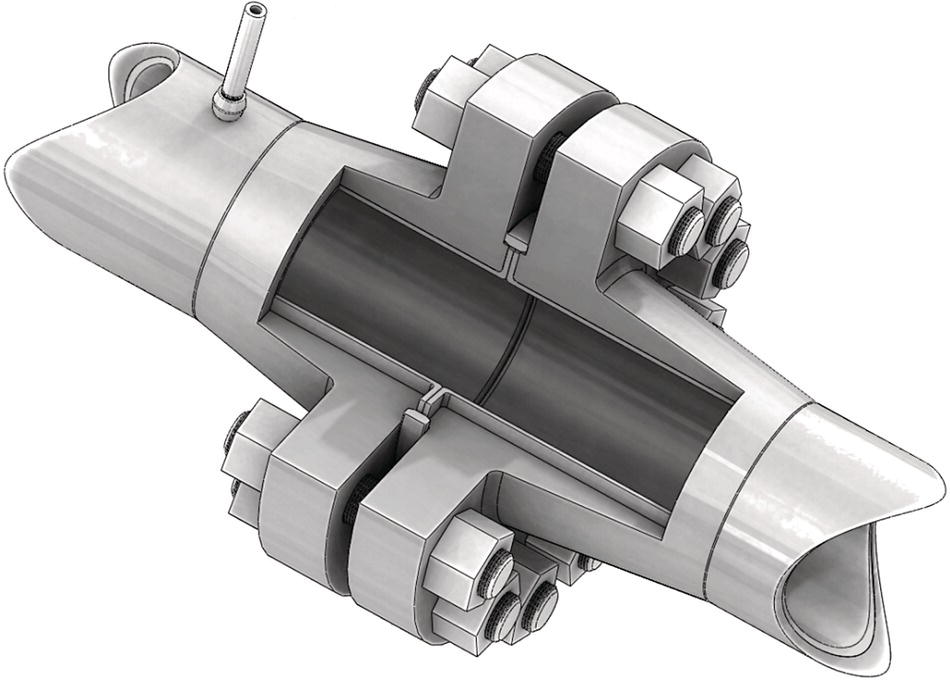
James F. Mason Mason Materials Development, LLC, Wyomissing, PA, USA Internal corrosion of oilfield pipelines has been an operating concern since the beginning of the industry. Of the many solutions adopted by the industry, few have the durability and reliability of the thermoplastic liner, which was introduced to oil and gas more than 30 years ago. In the intervening years, the technology has matured, with advanced materials and designs delivering high reliability and durability to pipelines from 50 mm (2 in.) to over 1000 mm (39 in.) in diameter. Thermoplastic liners consist of a thermoplastic pipe that is inserted into the metallic host pipe and terminated at each end with a corrosion-resistant coupling such as a thermoplastic-lined flange or a corrosion-resistant alloy welded connection (Figures 65.1 and 65.2). For onshore application, the flanged connection is generally preferred due to low cost and ease of installation, inspection, and maintenance. Thermoplastic liners are also used for offshore, subsea pipelines. In that case, welded, flangeless, connections are normally used. All thermoplastic liner materials are somewhat permeable to small molecules such as water, CO2, and H2S, which can cause corrosion. The liner works as a corrosion management system because a protective corrosion scale is formed on the interior pipe wall behind the liner shortly after going into service. The liner is a physical barrier that protects the scale layer from damage by the pipeline contents. As long as this protective scale layer remains intact, the corrosion rate from that time on is essentially negligible, and experience is that this is normally the case. One of the best reasons to use a liner is that it provides a double-containment benefit. If the liner fails, the pipeline contents are still contained. A repair can be completed on a nonemergency basis and without a pipeline spill. Liners are a preferred corrosion management solution in cases where the long-term reliability of chemical corrosion inhibition systems is in doubt, or inhibitor consumption rate is so high that it becomes more expensive than a liner over the lifetime of the pipeline, or when there is a significant erosion process in the pipeline caused by abrasive contents such as slurries or high-speed flow streams with entrained sand. Liners are almost always less expensive than specialty alloy steel pipes and, because the liner is an extruded pipe with a wall thickness of at least several millimeters, it provides a pinhole-free barrier—a benefit that high-performance internal pipeline coatings cannot guarantee. Liners are used in upstream pipelines transporting corrosive fluids such as produced water, oil well multiphase, and sweet or sour gas multiphase. In most applications, the liner retains a smooth interior surface over its entire service life, contributing to improved flow characteristics compared with aging, corroding steel. There is only one international standard that addresses thermoplastic liners for oilfield pipelines. NACE International Standard Practice SP0304, “Design, Installation, and Operation of Thermoplastic Liners for Oilfield Pipelines” [1] was first issued in 2004 and has recently undergone a major revision to include more complete design guidance. The Canadian Standards Association (CSA) has developed and regularly updates a comprehensive standard for thermoplastic-lined oilfield pipelines. Clause 13 of Canadian Standard Z-662 “Oil and Gas Pipeline Systems” [2] provides guidance on design and operation of thermoplastic-lined oilfield pipelines. The standard is based on decades of operating experience with thermoplastic-lined systems in Canada. Compliance with Z-662 is mandatory in Canada. Figure 65.1 Welded flangeless connector with corrosion-resistant alloy cladding in an unlined section. (Courtesy of United Pipeline Systems, Durango, Colorado, USA.) Figure 65.2 Fully lined flanged connection showing an annulus vent riser at the upper left. (Courtesy of United Pipeline Systems, Durango, Colorado, USA.) In addition to international and national standards, some oil companies have developed their own internal standard practices or specifications to which thermoplastic-lined pipelines must comply. Access to these proprietary standards by contractors and suppliers is on a case-by-case basis at the discretion of the oil company. Liners can be installed in new pipelines to provide corrosion protection from the start, or in existing pipelines to rehabilitate a corroding pipeline and prevent the progress of existing corrosion damage. There can be minor differences in the installation procedure for liner intended for new pipelines compared with installation of liner for rehabilitation purposes. The differences are largely in how the pipeline is prepared to receive the liner. New pipelines can be designed to accommodate the liner by a using large radius swept bends of at least 15X nominal pipeline diameter instead of elbows and small radius bends. The access points for liner installation can be planned and left uncovered after the rest of the pipeline is buried to facilitate access for liner installation. New pipelines normally do not need internal cleaning to remove corrosion product debris as is the case for pipelines being rehabilitated. The same types of end fittings are suitable for new and rehabilitation projects. Both flanged and flangeless designs are available (Figures 65.1 and 65.2). In rehabilitation projects, before liner insertion, the host pipeline must be prepared to receive the liner. This usually involves excavating the host pipe at convenient access points, cutting the pipe, and attaching an end fitting suitable for use as a liner termination to create a pipeline segment to be lined. In existing pipelines, elbows and short-radius bends must be cut out and replaced with swept bends with a radius of at least 15X the nominal pipeline diameter. Different installation techniques may have somewhat larger minimum radius requirements. The installer should always be consulted in this matter. For both new and rehabilitation projects, the segment length depends on the pipeline topography. Changes in direction increase the total frictional load and therefore the pulling force necessary to insert the liner, so the installation contractor will choose the access points to limit the insertion forces to a safe level below the damage threshold of the liner. Depending on local regulations, the segment might be hydrotested to ensure that the host pipe is capable of sustaining the design pressures of the lined pipeline. Any deficiencies in pressure capacity of the steel host pipe must be resolved before liner insertion. At one end of the segment, the contractor positions an instrumented winch with an accurate length counter and a load cell to measure pulling force. At this point, the contractor may run a sizing pig through the segment to test for any interior intrusions such as abnormally large weld roots, different ID repair sections, pipeline dents, kinks, and so on. If any are found, they must be fixed before liner insertion. The interior of the pipeline must be free of debris and loose corrosion products before insertion. In the case where the liner is being installed in a pipeline that has been in use and may have corrosion products on the internal surfaces, a wire brush pig is often used for this basic cleaning task. Some oil companies require treatment of the interior of the host pipe with a suitable corrosion inhibitor before liner insertion in both new and rehabilitation projects. Finally, the pulling cable is passed to the other end of the segment using a flexible-cup pig and air pressure so that the liner can be pulled in. The next step is the preparation of the liner. Liner pipe is normally delivered to the job site in lengths that are shorter than the length of the steel segment to be lined. These shorter lengths are joined together using a process known as butt fusion in which the ends of two segments to be joined are melted in a controlled manner and then pressed together under carefully controlled conditions until the polymer solidifies again. The process is repeated to join enough liner segments for insertion into the host pipe. For high-density polyethylene (HDPE) [3], polyamide 11 (PA11) [4], and polyamide 12 (PA12) [5], there are standardized procedures for this process, although most installers optimize and fully qualify their own procedures to accommodate the environmental and operational realities of the field. A specially designed pull head is attached to the liner. The pull head is then connected to a pulling cable via a swivel to prevent torque loads from transferring to the liner from the cable. If any special diameter reduction devices are to be used, the cable passes through these devices before being attached to the pull head. The liner is then pulled through the diameter reduction devices and into the host pipe. The ends of the liner are then terminated in the end fitting. For the flange fitting, it is necessary to fuse on a flange adapter made from the same type of polymer as the liner. If the machined polymer flange adapter is not available, a suitable flange adapter may be thermoformed at the end of the polymer liner segment. After the liner is inserted, it is normal to do an integrity check using compressed air. This may be done on a segment-by-segment basis, or the whole pipeline can be tested as one unit. During this pressure test, the annulus vents at each flange are monitored for excess flow from the annulus between the liner and host pipe, which would indicate a breach in the liner that must be repaired before commissioning. Some jurisdictions require a full hydrotest before the lined pipeline can be certified for use. Just as there is a pressure drop across a given segment of pipeline, the annulus also has a pressure drop that encourages migration of permeated gases to the downstream end of the segment, resulting in a preferential accumulation of permeated gases at that end. Before burial, the vents are connected to riser pipes terminated aboveground to a venting control system, which might be as simple as a hand-operated valve at the end of a small diameter riser pipe. When necessary, the vent ports of several adjacent lined segments may be connected with jumpers and vented through a valve at the downstream end of the chain. More sophisticated venting systems may include automatic vent valves that open at a certain pressure differential and pass the gases into a manifold that runs along the pipeline path. A benefit of the hand-operated valve is that an inspector can operate the valve periodically and observe the pressure and flow of gas from the vent. The presence of an unexpectedly high pressure or flow volume may signal a liner failure. The lined pipeline system is a composite system in which the host pipe bears all the same mechanical stresses as it would in an unlined system. It is important to remember that the liner is not designed to be a load bearing component. Its sole function is to separate the host pipe from the corrosive pipeline contents. Liners are normally designed to be just thick enough to facilitate proper fabrication and installation, plus any added thickness needed to address resistance to radial liner collapse. Thermoplastic polymers are not perfect gas barriers. Because of this, gases in the pipeline contents will permeate through the liner into the space, known as the annulus, between the liner and the host pipe, eventually reaching the same partial pressure in the annulus as in the pipeline contents. If the pipeline is depressurized with a high gas pressure in the annulus, it is possible that the liner will collapse by radial buckling to accommodate the expanding annulus gases. Collapse of the liner is generally considered to be a catastrophic event requiring replacement of the liner. To prevent annulus gas pressure buildup, the annulus must be vented continuously or periodically through the venting systems described earlier. The pressure differential across the liner wall required to cause radial buckling is known as the critical buckling pressure, Pcrit, which can be approximated for an unconstrained liner pipe by where E is the Young’s modulus of the liner material, t is the thickness, and r is the average radius of the liner. Liners can be installed in three stress states: loose, neutral, and tight. Each type results in different constraints on the liner and offers advantages and disadvantages to system design and performance. When discussing this topic, it is essential to remember that thermoplastic liner materials are generally elastoplastic. In this context, it means that they exhibit elastic behavior over the range of strain from zero to the tensile yield point, after which they exhibit plastic, irreversible, deformation. They also exhibit creep behavior. When held under load at strains below the yield point for long periods of time, the material undergoes partial stress relaxation leading to some unrecoverable strain after the load is removed. In the case of loose-fitting liners, commonly called “slip-lining,” at the time of insertion the outside diameter of the liner is smaller than the inside diameter of the host pipe when the liner is not pressurized. On pressurization, the loose liner may expand to contact the interior surface of the host pipe, thereby transferring the hoop stress to the host pipe. When held under pressure, especially at elevated temperatures, the liner may stress relieve and remain in close contact with the steel host pipe after the interior pressure is removed. But usually, under field installation conditions, and especially in colder climates, loose liners may move slightly away from the wall of the host pipe when not under pressure because the deformation during the initial pressurization is not sufficient to cause fully plastic deformation at the strain required for contact with the host pipe inner wall, and/or the time allowed at high temperature was not sufficient to allow complete stress relaxation, or the pressurization water temperature was not sufficiently high to accomplish the stress relaxation job in the time allowed. Over time creep, stress relaxation, thermal expansion, and swelling due to absorption of hydrocarbons at the operating conditions may reduce this tendency, but it is unlikely be completely eliminated. Neutral-fitting liners are those in which the initial outside diameter of the liner is the same as the inside diameter of the host pipe. For insertion, it is usually necessary to temporarily reduce the diameter if the liner slightly through mechanical means, especially for long segment insertions. Axial loading during pull-in prevents reversion to the initial diameter. When insertion is complete and the axial load is removed, the liner reverts to its initial diameter, making contact with the host pipe interior wall with no residual stress in the liner material. Tight-fitting liners are designed to have an initial, preinstallation, outside diameter that is slightly larger than the inside diameter of the host pipe. The liner must be reduced in diameter by mechanical means to be smaller than the inside diameter of the host pipe for insertion. Axial loading during insertion prevents reversion during the insertion process. When the load is removed, the liner will elastically recover until it contacts the host pipe wall. At this point, the liner is still in radial compression with a reaction force that is pushing out against the host pipe wall. Liners in gas and multiphase gathering services are more prone to collapse due to annulus pressure buildup than liners used in water injection service, which does not contain gas to permeate into the annulus. Liners in hydrocarbon service undergo changes in stiffness and dimension as they absorb hydrocarbons from the flowing pipeline contents. Designing the liner to be collapse resistant requires knowledge of the modulus of the polymer at equilibrium in the chemical environment and at the temperature of service. These characteristics can be determined through laboratory studies and are very useful to liner designers [6]. The following equation can be used to calculate the collapse pressure Pcrit of a tight-fitting liner [7]: where Neutral and tight-fitting liners are installed using special diameter reduction equipment so that during insertion the OD of the liner is less than the ID of the host pipe. The principal methods of diameter reduction are conical die reduction [8] and roller-box reduction [9]. In both cases, the diameter of the liner is reduced while under axial tension by passing through a device that concentrates compressive hoop stress along a narrow zone of the circumference of the liner pipe. As the diameter is reduced, the liner pipe downstream of the diameter reduction device gets longer, as would be predicted by Poisson’s ratio. Because the deformation is less than the yield strain, the liner can recover nearly 100% of its initial diameter when the axial load is removed. The implications of installed stress state (tightness) on liner performance are profound, affecting how the liner should be installed and operated, and the likely failure modes. Tightness can also affect the maximum lined segment length. Depending on the service type (gas, liquid, multiphase, abrasive slurry, etc.), liner tightness affects, for example, venting frequency, permissible pressure cycle range, and pigging procedures. Understanding the dynamics of the liner after installation is critical to the successful operation of a lined system. Tightness affects the resistance of the liner to collapse or radial bucking. The critical buckling pressure is the differential pressure across the liner wall that results in radial instability, leading to buckling and collapse of the liner. Several studies have concluded that for a given liner wall thickness, tighter liners have a higher critical buckling pressure than looser liners [10–13]. These studies also confirm that thicker liners have a higher buckling pressure than thinner liners for the same tightness. Because thermoplastic materials have a much larger thermal expansion coefficient than metals, the plastic liner will try to lengthen much more than the steel host pipe when there is a temperature increase. This can happen when the liner is installed in winter at low ambient temperature and operated at a much higher temperature. Let us consider the case of a HDPE liner installed at −20 °C and operated at 60 °C. The coefficient of linear thermal expansion of HDPE is 116 × 10−6 m/m/°C (2.13 × 10⁻⁴ ft./ft./°F), which is about 9X more than the coefficient for steel. Using these temperatures, we calculate that the 80 °C temperature change will result in 9.28 mm/m (0.114 in./ft.) length change. Over the length of a 500 m (1640 ft.) liner segment, the total unconstrained length change is 4.64 m (15.2 ft.), while the steel will only lengthen about 0.5 m (1.6 ft.). Because the ends of the liner are constrained, the resulting stress in the plastic material can result in axial buckling, also known as “accordion buckling,” which is one of the principal failure modes for liners. Tight-fitting liners are much more resistant to this failure mode because of the large frictional resistance to axial movement when the liner is in radial compressive contact with the host pipe. The increase in temperature increases tightness, too. Neutral-fitting liners have some frictional resistance to axial movement, and loose-fitting liners have much less. During installation, expert contractors will often add some “stretch” to the liner before capturing the ends within the end fittings at the low installation temperature. This elongation, fully within the elastic range of the polymer, offsets some of the anticipated thermal expansion because as the liner increases in temperature and gets longer, the elastic stress stored during the stretch is relieved, resulting in a near-zero axial loading at operating temperatures while maintaining radial compression of the liner. In principle, any thermoplastic material can be used as a liner for oilfield pipelines. Polymer material properties are often reported at standard laboratory temperature, around 23 °C, and without any chemical exposure conditioning prior to property measurement. These properties are significantly affected by temperature and may be greatly affected by chemical exposure. All key properties should be reported at or above the design temperature of the pipeline. There are several important criteria that affect the material choice: Because of its relatively low cost, widespread availability, ease of production and installation, and long history of successful service in oil and gas applications, HDPE is the most frequently used thermoplastic for oilfield pipeline liners. The basic engineering grades of HDPE, designated PE-4708, and PE-4710 in the ASTM classification system [14], or PE 100 in the International Organization for Standardization (ISO) classification system [15] have become the preferred grades for liner applications, although medium density materials such as PE-2708 and PE80 may be suitable especially in water applications. HDPE can be affected significantly by hydrocarbons in the service environment. The effects include swelling and loss of stiffness, but these effects can be accounted for when designing a liner if the effects are quantitatively known [16]. The effect is more severe at higher temperatures. Hydrocarbon absorption causes reduction in modulus, which reduces the critical buckling pressure. The attendant swelling increases the liner tightness, partially offsetting the loss of modulus until the point that the internal stress in the swollen, softened HDPE is relieved by buckling of the liner at some random mechanical defect point. Even a minor defect can be the initiation site. Even so, at temperatures up to about 65 °C, HDPE can be a good choice for most liners in hydrocarbon transport pipelines. For water transport pipelines, the upper temperature limit depends on the amount of hydrocarbons in the water. Modern bimodal HDPE materials, such as PE100, PE4710, and PE-RT (polyethylene of raised temperature resistance), have been successfully used in water lines up to 80 °C with proper design and operation. In the case that the operating conditions are too severe for HDPE, there are alternative materials available. PA11 [17] and PA12 [18] have been used in hot, sour hydrocarbon, and multiphase pipelines with good results in appropriate service conditions. PA11 and PA12 have been used as the pressure barrier, essentially a liner, in offshore flexible pipes that comply with API Spec 17J [19] for more than 25 years. Polyamides are condensation polymers that can be depolymerized (degraded) by water under the right conditions. Acid conditions accelerate the process. The lifetime of the PA11 and PA12 materials can be predicted with reasonable accuracy using the methodologies of API 17 TR2 [20]. The grades of PA11 and PA12 used for liners are subject to damage when large amounts of methanol are used in the pipeline [21]. The methanol can affect the mechanical properties of the polymer at use temperatures and, at very high temperatures, accelerate degradation of the polymer. The manufacturers of these polymers can offer guidance on suitability in the design conditions. Other engineering polymers such as polyvinylidene fluoride (PVDF) and polyetherether ketone (PEEK) have also been studied from use as liners in oilfield pipelines [7]. Laboratory data indicate that these materials are promising for field use. Pipelines that are fitted with liners are operated differently compared with unlined systems. The differences are related almost entirely to preventing liner damage such as collapse and axial buckling. When liners are new, there is always some residual gas and/or liquid trapped in the annulus. This is a normal consequence of the installation process. As the lined pipeline is operated, these bubbles will move downstream, following the pressure gradient, until they reach a liner termination. This volume must be removed periodically by operating the vents located at each segment termination point. Over time, these fluids will be purged from the annulus. Once the annulus is purged of gases and liquids, unless the pipeline is going to be used in gas or multiphase service, the vents need not be operated except occasionally to check liner integrity. Local regulations may specify this inspection interval. When there is gas in the pipeline during normal operation, some gas will permeate through the liner and eventually accumulate at the downstream termination of the lined segment. This permeated gas must be vented off or there will be a greatly increased risk of liner collapse and loss of protection. Expert installers normally recommend a venting schedule based on their knowledge of the material and pipeline service conditions as provided by the operator. Some jurisdictions may require specific vent inspection intervals. A general rule is that venting should be done frequently during the first few months, perhaps starting weekly, then biweekly, then monthly, and as the amount of annulus gas vented declines at subsequent venting operations, the venting frequency can be reduced. Nevertheless, checking the vents periodically is a critical inspection technique to verify liner integrity. Operators must be aware of the likely vent fluid composition. It may not be the same as the pipeline contents because of the differential permeation rates of the different species. Annulus gas analysis may not show the same concentration ratios of gases that are in the pipeline. For example, if H2S is the fastest gas permeant, it will grow in concentration in the annulus faster than more benign gases, potentially creating an increased hazard during the venting operation. Hazardous conditions could exist if the gases vented are highly toxic such as with H2S. It may be necessary to use scrubbing equipment or a self-contained breathing apparatus when manually venting an annulus with a potential inhalation hazard such as sour gas pipelines. It is also important to recognize that venting must be done even in bad weather and unfavorable terrain and plans made to account for this. Venting systems have been known to plug because of solid debris in the annulus that moves to the vent, or because of ice plugs. If there is a potential for liquid ice plugs in the vent riser, it may be necessary to heat-trace the riser for cold weather operations. Lined pipelines should never be allowed to go under vacuum without first operating all the annulus vents while the pipeline is under full line pressure to remove accumulated gas, then taking special care that all the vent valves are completely shut before reducing line pressure. Since atmospheric pressure is greater than internal pressure when the pipeline goes under vacuum, the result will be liner collapse as air rushes through open vents into the annulus and the flexible liner complies with the pressure differential. This is usually a fatal condition for the liner. In upset conditions where advance venting is not possible, the liner should be inspected by operating each vent valve after return to stable operation. If there has been a liner breach, there will be a steady flow of fluid at the vent. A successful design approach to deal efficiently with permeated annulus gases is the grooved liner concept. In this design, the outer surface of this tight-fitting liner has small axial grooves that facilitate transport of gases to the vents [22]. This may be the preferred solution in cases when the amount of permeated gas is expected to be large or when it is imperative to prevent liner collapse and the ability to effectively vent permeated gases from the annulus of a conventional tight-fitting liner is in doubt. To accommodate the grooves, the liner can be designed slightly thicker so as not to compromise the collapse resistance. In this design, venting is critical. The cumulative volume of the grooves is very large compared with volume normally found in the annulus of a tight-fitting smooth surface liner system. This large volume at high pressure is more than capable of collapsing the liner if the pipeline is depressurized while the annulus is at high pressure. These examples are intended to illustrate success and failures in lined pipeline systems and not necessarily to illustrate leading edge, innovative liner use. Because it can take years for concepts to be proven good or bad, it is most useful in a review to highlight what has been shown to work well, and what has been shown to have problems. Petroleum Development Oman LLC (PDO) has been operating polyethylene (PE) liners since 1988, first with water injection pipelines, and eventually with hydrocarbon flow lines. Experiences in PDO were reported by de Mul et al. [23]. Their first PE-lined crude product pipeline was installed in 1992. They reported that they have used PE liners in over 150 water and crude product pipelines in diameters up to 864 mm (34 in.). The liner design was established using properties of the PE liner material at equilibrium conditions of hydrocarbon absorption at the operating temperature. Their liners are designed to resist collapse but are not so thick that they are inherently collapse resistant against full line pressure in the annulus. This was found to be too conservative if annulus pressure was properly managed by operating the vents at regular intervals. They reported that the minimum specified collapse pressure for their designs is 3 barg (43.5 psig). The upper temperature limit for PE-lined pipelines was established at 60 °C using the best PE materials available at the time. For water lines with PE liners 70 °C was the upper temperature limit. In practice, PDO’s experience with crude flow lines ranges from 10 to 90 barg (145–1350 psig) operating pressure and 30–50 °C operating temperature with very good outcomes provided that appropriate attention was paid to good field practices such as venting. Kinder Morgan chose to use a grooved PE liner in 29 km (18 mi.) of their gathering system in the Yates Field in west Texas, the United States [24]. That asset already was using more than 13,533 m (44,400 ft.) of PE-lined steel in diameters from 152 to 406 mm (6–16 in.). For the new, grooved liner design pipelines, the diameters ranged from 102 to 610 mm (4–24 in.). The grooved design was chosen because the produced fluid was from a reservoir that was under tertiary oil recovery using high-pressure CO2 injection. The produced fluid was a hot, highly corrosive mixture of oil, water, gas, and CO2. The decision to use a grooved liner instead of a typical tight-fitting liner was made because the amount of CO2 permeating throughout the PE liner was projected to be large at the production temperatures. A North Sea offshore operator used a PE-lined, reeled, water injection pipeline for 13 years before a sample was removed for testing and analysis during a scheduled shut down to modify the subsea production system. The liner was inserted as a tight-fitting liner at an onshore spool base using a proven diameter reduction technique. Extensive testing and analyses were conducted on the specimen and reported in 2010 [25]. Lined steel segments of 472 m (1548 ft.) length were joined using a welded, flangeless connector to comprise a single length to be deployed offshore. Comparison of the recovered liner polymer with retained, unexposed polymer of the same pipe lot showed that the liner had not stress-relaxed during service and had retained the interference fit of the initial installed condition after reeling onto a reel-lay barge, unreeling at the installation site, and 13 years of service. Pull-out testing of the recovered sample showed that the liner remained securely captured in the segment end fitting joint up to the yield stress of the polymer. Corrosion on the internal surface of the steel pipe that was protected by the liner was superficial. Metallographic analysis showed that the worst-case corrosion was 1.6% (280 μm or 0.011 in.) of the nominal wall thickness of 17 mm (0.67 in.). The majority of the steel surface was not corroded and was covered by cracked mill scale. BP America, then operating in the 1990s as BP Amoco in Canada, operated a network of highly corrosive sour gas and gas condensate pipelines in Alberta, Canada [26]. A 101 mm (4 in.) carbon steel pipeline transported gas condensate, sour gas, and salt water from the well to a separator facility about a mile away. Operating temperature was 65 °C and operating pressure was 41.4 barg (600 psig). HDPE liners with a tight design were installed by a reputable and experienced contractor. After 6 months of normal operation and frequent venting, it became impossible to adequately remove pressure from the annulus, indicating a likely failure. When the line was excavated for a repair, it was discovered that the liner had sustained a major collapse failure and loss of containment. A new HDPE liner was installed with shorter lined segments that should make it easier to control annulus pressure and move permeated gas to the vents, and a more neutral fit that would be more forgiving as the liner material became swollen by hydrocarbon absorption. This liner lasted approximately 18 months before failure. A third HDPE liner was installed using the same design. An economic value calculation indicated that the liner could be replaced every 18 months and be less costly and more reliable than an inhibition program. When the third liner was scheduled for replacement, engineers concluded that a liner made from PA11 offered the possibility for a much longer lifetime in service. PA11 had been used extensively in offshore flexible risers and flow lines as the fluid containment barrier for more than a decade. Through trials in the laboratory and the field, it was concluded that PA11 could be installed using the same techniques as for HDPE, but with minor modifications. The operator reported that annulus vent pressures rose much more slowly than for any of the HDPE liners. This is because PA11 has a much lower permeation rate for hydrocarbons than HDPE and is not swollen by liquid hydrocarbons. Swelling is responsible for a large increase in permeation rates in HDPE compared with unexposed material. Samples of liner were recovered during normal maintenance by removal of a test spool located in line with the production fluids. Analysis revealed excellent retention of properties after more than 3 years being exposed to the production environment [17]. The operator also deployed PA11 liners in several other high-temperature sour gas pipelines with good success and meaningful learnings. Eventually, another operator, TAQA North Ltd., acquired the assets with the PA11 liner described earlier. The well that produced sour multiphase fluids through the PA11-lined pipeline was decommissioned by TAQA in 2016. The liner had operated since 1996 without a material-related problem. In 2015, TAQA decided to install a PA12 liner in a pipeline transporting sour multiphase crude from another well in the same field after having multiple problems with HDPE liners in the sour, multiphase conditions. [18] The PA12 liner has been operating as designed since then. Shell Canada Limited installed tens of kilometers of PA11 liner in 152 and 203 mm (6 and 8 in.) pipelines in a highly sour gas field in southern Alberta, Canada in 2000 [21]. Due to the higher cost of PA11 compared with PE, a thinner liner wall was chosen. To accommodate long segment pull lengths of up to 800 m (2625 ft.), a slightly loose design was chosen. This design choice was based on laboratory evidence that the PA11 material, being much more fatigue resistant and ductile than HDPE, would be collapse tolerant—the idea that multiple cycles of partial collapse and re-rounding under pressure cause by line pressure fluctuations while gas was in the annulus would not damage the liner. Operating pressure was 7000 kPa (1015 psi). For about a year after installation, the liners performed as expected, but eventually it became difficult to control annulus pressures. In 2002, it was discovered that liner breaches were happening. The causes were multiple. The most general learnings from this experience are that loose designs are not a good idea for high-pressure gas. They allow too much axial motion due to flowing gas drag and can result in axial collapse and loss of containment. Polymer properties change with the absorption of injected fluids must be considered including softening and swelling with fluids absorption or shrinkage and stiffening with the extraction of plasticizing species. Most of the liners installed in the original construction were removed and replaced with a collapse resistant grooved HDPE liner. Shell encountered problems after replacing the PA11 liners [27, 28] with HDPE. The steel pipeline failed due to internal corrosion after just under 4 years of service. There was no evidence of liner failure prior to the steel pipeline failure. A thorough investigation concluded that the failure was caused by internal corrosion that had reduced the steel thickness to about 10% of the original thickness in the area of the failure. Although pipeline segments located away from the failure site had fully intact iron sulfide scales, it appears that the protective iron sulfide scale did not cover the steel surface completely in the area of the failure, leaving patches unprotected and susceptible to corrosion. Between the HDPE liner and the steel pipe, they found a paste-like substance consisting of an iron sulfide corrosion product, small amounts of formic acid, and an acidic liquid, which they identified as mostly methanol. Methanol was used as a hydrate inhibitor in normal pipeline operations and, under the conditions of the subject pipeline, was vaporized downstream of the injection site. This increased the permeation rate of methanol through the HDPE liner. Since HDPE is not a perfect barrier to methanol, some methanol permeated through the liner and came to reside in the annulus. Formic acid from downhole treatment chemical mixtures also can permeate the HDPE liner. They concluded that methanol and water, by themselves, were corrosive in the conditions of the annulus and that the presence of formic acid accelerated the corrosion rate in the absence of a fully intact protective scale. Shell has changed the operating practice to address this issue, and it has proven successful.
65
Thermoplastic Liners for Oilfield Pipelines
65.1 Introduction
65.2 Codes and Standards

65.3 The Installation Process
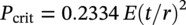
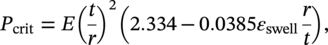
65.4 Important Mechanical Design Aspects
65.5 Liner Materials
65.6 Operating a Pipeline with a Liner
65.7 Lined Pipeline Systems—Application Examples
65.7.1 Liners in Hydrocarbon Flow Lines
65.7.2 Grooved PE Liners
65.7.3 Liners in a Reeled, Water Injection Pipeline
65.7.4 Liners in Sour Gas and Gas Condensate Pipelines
65.7.5 PA11 Liners in Sour Gas Pipelines
References
Thermoplastic Liners for Oilfield Pipelines
(65.1)
(65.2)