“You do not get what you expect – you get what you inspect” —(origin unknown) Our malfunctions survey (Table 1.1) included installation mishaps among the top five causes of tower malfunctions. Installation malfunctions lead to poor separation, lost capacity, instability, higher energy consumption, and higher carbon footprint, all with negative economic and HSE impact. In some cases, a tower may cease to work, forcing a premature outage. Proper inspection following construction and during turnarounds is the best tool to identify installation mishaps, design oversights, fouling, and damage and correct them before they hurt. Tower inspection is critical for trouble-free operation. In new and revamped columns, inspection is the last opportunity to detect any design, fabrication, or installation errors prior to startup. In existing towers, it is the last opportunity to detect and repair damage and undetected flaws and clean up any plugged or fouled internals. Remaining flaws are likely to bring about poor performance and even mechanical damage or HSE issues. Troubleshooting guru Norman Lieberman (290) describes a tower he designed but did not inspect that flooded prematurely due to an uninstalled impingement plate on the reboiler return. The author has a similar story about a revamp that he designed but did not inspect that fell short of meeting expectations due to a minor detail that would have been easily detected had he inspected it. Both of these experiences teach that good hard work can go down the drain due to a lack of inspection. Do not fall into this trap. Remember: you do not get what you expect – you get what you inspect. Prior to startup, the cost and effort of rectifying flaws is often negligible, becoming enormous after the startup. Additionally, new flaws introduced during the outage are extremely difficult to identify. Unlike the fabrication and design, which are usually well documented by drawings, specifications, and correspondence, few (if any) records are kept of the installation or the differences between the “as-built” tower internals and their drawings. If the tower performs poorly, there is often a scant basis for suspecting an assembly error. Nonetheless, a decision to shut a tower down for reinspection often hinges on this basis. A premature shutdown is extremely costly and may turn out most embarrassing if it fails to cure the problem. Inspection is one of the few times that process and plant engineers get to see the inside of equipment. It is an invaluable training opportunity. In half a day inside a tower, one can learn more about distillation towers than in a full university semester. So it is an opportunity not to be missed, especially for the inexperienced. To get the most out of such an inspection, it is crucial to know what to look for to prepare ahead of time. The author has seen cases when engineers entered the tower without adequate preparation and learned very little. This chapter reviews the common issues inspectors should look for and many of the tools that can help them achieve the most out of these inspections. It also describes good and bad practices for troubleshooting tower internals installation and assembly by inspection. Working in the confines of a column is potentially hazardous. Appropriate safety precautions are required to mitigate the hazards. Many of these precautions are required by law, The Occupational Safety and Health Administration (OSHA) standards, company standards, and other regulatory bodies. It will take a book just on this subject to describe all these. Such a description is outside the scope of this book. The aim of this section is to provide a brief generic overview of some of the key potential hazards in working inside a tower during installation, removal, inspection, and cleaning work. The list is far from comprehensive. To address each of these hazards, it is necessary to follow statutory regulations, OSHA standards, company standards and practices, safety supervisors’ guides, and other requirements. The hazards list is not intended to apply to any specific application, nor to replace any statutory or company standards. Common safety hazards include: The author strongly recommends declining or aborting a tower inspection if you are not satisfied that all the relevant hazards have been properly addressed or if you have any physical limitations, concerns, or fears that may limit your ability to perform the inspection. Remember also that inspection is a dirty job, which may unsettle your social or family life for a few days. There is a very important rule of thumb presented by Bouck (42): Know your limits. Your and others’ safety depends on you. Inadequate preparation of trays prior to installation may prolong the turnaround, adversely affect column performance, and even lead to safety issues. The guidelines below (43, 192, 307, 319) can help minimize these problems: Carbon steel trays and internals need protection from a damp atmosphere. Inside storage is recommended even when these internals have surface protection. Stainless steel does not require such protection, so the conventional wooden crate with tarred paper or plastic lining is often considered adequate (25). This is imperative with specialty and proprietary trays. Supplier drawings often omit key details, in some cases due to confidentiality concerns, leaving installers with no idea how certain parts fit in. The mock assembly unveils such details in time to contact the suppliers and obtain their guidance. In one case (43), such a mock installation identified a fabrication error that would have prevented the high-capacity trays from attaining their high capacity. Early detection enabled a remake within the time constraint. The author had similar experiences. A mock-up installation on the ground is also useful in other complex tray designs. In one case (43), a mock-up installation identified an issue with a modification of a complex chimney tray that decanted water. Had this modification been installed as shown on the drawings, the tray would have been dysfunctional. In another case, a mock-up installation of specialty trays at the vendor shop allowed a thorough inspection and was invaluable in reducing the tight installation time in a revamp. In addition, temporary strainers can be installed in outlet lines, especially those feeding pumps. Plugs are more effective than strainers alone, because some debris can get through strainers or damage strainer elements and then pass through them. In one case (434), blockage by debris broke strainers, and pieces of strainer casings damaged the pump. Strainer casings should be mechanically strong enough to withstand pump suction when fully blocked. Inadequate preparation of packing prior to assembly may prolong the turnaround, adversely affect column performance, even lead to safety issues. The guidelines below can help minimize these problems. Steps 2, and 4–7 primarily apply to random packings; steps 1, 3, and 8–10 apply to both random and structured packings. It is necessary to be familiar with the nature of the oil and, if needed, to adequately remove it. It is best to seek the supplier’s advice on the preferred removal procedure. Alternatively, the supplier can be requested to use a water-soluble lubricant in the press, which can be washed during commissioning, or to degrease the packing with solvent after pressing. Early removal of the oil may cause corrosion and should be avoided. Figure 10.1 Samples of ceramic saddles fresh from shipment. (a) Chipped saddles. (b) Nonuniform saddles. (From Kunesh, J. G., Chemical Engineering, p. 101, December 7, 1987. Reprinted with permission.) Figure 10.1 shows a few samples of ceramic saddles as received from shipment. The breakage (Figure 10.1a) is mainly of chipping at the corners (267). The large pieces can still be used, but the chips must be screened out as they are likely to lower the column capacity and increase its pressure drop. Screening must be carefully performed and closely watched; otherwise, it may cause more particles to break than it removes. In some cases (e.g., 267), it is necessary to pick chips out by hand. Figure 10.1b shows the size nonuniformity of saddles of a single nominal size as received from one shipment. Instead of ordering spare packings, the supplier can be requested to provide enough packings to fill the bed to the required height. The supplier will then allow for the spare volume. With ceramic packings, additional allowance should be made for any breakage occurring past the point where the supplier’s responsibility ends. Before selecting a supplier, manufacturers should be requested to submit samples for testing, and any unsatisfactory test results should be discussed. A desirable (or acceptable) performance specification should then be developed and included in the purchase order. Samples of the final shipment should be retested. Horizontal support rings left in the tower interfere with liquid distribution and reduce the available open area, with possible adverse effects on packing efficiency and capacity. Straight downcomer supports or other vertical bars are generally far less detrimental to distribution and open area, but make the installation of structured packings difficult. These are usually removed only if they are expected to adversely interfere with the new internals, their installation, or liquid flow through them (461). Some designers (340) prefer to always remove them. Inward projections of manholes can also interfere with the installation of structured packings, in which case they need to be removed (84). Strigle (461) states that with random packings, tray support rings need only be removed when they occupy more than 10% of the column cross-sectional area. Strigle’s recommendation for the maximum acceptable support ring width depends on column diameter, as shown in Table 10.1. In one 13.5-ft-diameter column (413), random packings performed well even though the tray support rings were not removed. In another case (432), the replacement of poorly performing trays by random packings in an amine absorber was only partially successful in improving performance, presumably because the support rings and downcomer bolting bars were not removed. Table 10.1 Maximum acceptable tray ring width left in a tower retrofitted from trays to random packings (461). With structured packings, it has been recommended to always remove the support rings prior to packing installation (174). Tests in a 3-ft-diameter column with a 14-ft-tall bed of structured packings showed that leaving in the 2″ tray support rings resulted in a 10% efficiency loss and a 40% rise in pressure drop. In larger columns, the support rings usually occupy a smaller fraction of the column area, and the pressure drop rise is likely to be smaller. The efficiency loss may escalate in taller beds due to distorted distribution profiles and in larger-diameter towers due to the higher ratios of tower diameter to packing diameter, which diminish the effect of lateral mixing (Section 4.3). In order to minimize irregularities and dead liquid pockets at the tower wall, it has been recommended to internally blind unused nozzles (340) in the packed zone. Inadequate removal of existing trays or packings can endanger workers, damage equipment, and prolong the shutdown. The following guidelines can help minimize the above problems: The air above the water level should be continuously monitored for explosivity and toxicity. When a hydrocarbon or water-insoluble organic is present in a small concentration in the water, the high repulsion of the water phase imparts a very high activity coefficient to it. Its volatility becomes several thousand times that of the pure component, which sends it into the air, where it can exceed the lower explosive or the allowable exposure limit. The objective of correct tray installation is to follow safe practices while minimizing installation errors and installation time. Practices prior to installation that help achieve the above installation objectives are presented in Section 10.2.1. This section discusses practices that help achieve the above objectives during the installation period: Random packings can be either wet-packed (Figure 10.2a) or dry-packed (Figure 10.2b,c). With wet packing, the column is filled with water following the installation of the bottom support plate. Packing pieces are gently poured from a short distance above the water level and are “floated” to the bottom. The water cushions the fall and promotes random settling. With dry packing, the packing pieces are dumped from a certain height above the top layer of packing. Figure 10.2 Random packing installation techniques. (a) Recommended wet packing technique; (b) recommended dry packing technique; (c) the chute and sock method of column packing; (d) bad packing technique, promoting hill formation. (Parts (a) and (b): Reprinted Courtesy of Koch-Glitsch LP. Part (c): From Chen, G. K., Chemical Engineering, p. 40, March 5, 1984. Reprinted with permission. Part (d): From Kister, H. Z., “Distillation Operation,” Copyright © McGraw-Hill, 1990. Used with permission of McGraw-Hill.) Wet packing minimizes breakage, compression, and mechanical damage to packings and supports. It also maximizes random settling and reduces packing density. This reduced packing density provides a small capacity gain and pressure drop decrease compared with dry packing and minimizes the required number of packing pieces per unit volume. Billet’s experiments (34) with 1½” Pall rings in a 20-in-diameter column showed that changing the packing technique from dry to wet increased column capacity by about 5%, lowered column pressure drop by up to 10%, reduced the number of packing particles by about 5%, and had a negligible effect on efficiency. The author also observed a 5% capacity improvement after switching the packing technique of a 3-ft column from dry to wet. Ludwig (305) reported cases in which the pressure drop was lowered by 50 to 60% and even more by switching the packing technique from dry to wet. The author believes that Ludwig’s cases are for ceramic packings in which breakage played an important role in increasing the pressure drop of the dry-packed beds. Dry packing avoids the introduction of water into a dry process, high hydrostatic heads, minimizes rusting of metal packings, and is quicker and less expensive. It is generally preferred in most modern metal and plastic packing applications, especially in the following applications: Listed below are applications where wet packing is advantageous. Wet packing is strongly preferred for breakable packings (step 1). For the other steps in the list below (2–4), wet packing offers a smaller advantage: Poor packing installation may induce maldistribution, flooding, loss of efficiency or capacity or both, instability, and excessive pressure drop (31, 305, 339, 518). Bad packing installation practices may also damage packings and supports. When correctly done, either wet or dry packing can provide good performance. Both techniques have traps. Failure to avoid these pitfalls, rather than a nonoptimal choice between wet packing and dry packing, is usually responsible for column malfunctions. Several guidelines for avoiding these pitfalls are listed below. Caution is required when dumping the first 2 to 3 ft of packings, as excessive fall height can damage the support plate or crush the packings. The support plate is usually of the gas injection multibeam type (140, 192, 407), clamped to a support ring. The levelness of the ring is not critical, and normal construction tolerances are usually acceptable (407). In near-freezing conditions, the fall height of plastic packings should not exceed 4 ft. The impact resistance of plastic often diminishes at low temperatures, and it is prone to breakage. In one case (192), polypropylene rings were dropped from a height of 23 ft onto a steel support at about 15°F, and 20% of them were damaged. Incorrect installation has caused numerous failures in columns containing structured packings. Inclined layering, incorrect layer orientation, heavy-footed stepping on structured packings, failure to achieve a snug fit of packings to the tower wall, and excessive compression of packings in an attempt to achieve a snug fit are a few of the many causes of poor performance. Some of the lessons learned are described below: Figure 10.3 Installation of structured packing elements. (a) Fitting the elements in one layer; (b) 90° rotation of one layer with respect to the layer below. (From Horner, G. V., The Chemical Engineer, (Supplement), p. 8, London, September 1987. Reprinted with permission.) Figure 10.4 Some steps in good practice of structured packings installation. (a) Lowering elements of packings using ropes. (b) Bending wall wipers outward. (c) Using a slide plate to fit centerpieces. (d) A gap between elements due to tower out-of-roundness. (e) Using filler sheets perpendicular to packing layers to fill the gap. (Copyright © FRI. Reprinted Courtesy of FRI.) Because of the multitude of installation traps that can impair the performance of structured packings, it is best to have the supplier provide an installation team. If impractical or too costly, the supplier should be requested to provide detailed installation instructions, which must be strictly adhered to, as well as a supervisor (at cost) to supervise the installation. The supervisor’s scope of work should include thorough hands-on training for the installation crews and watching that the packings are correctly installed. At times, a tower is to remain idle until there is economics to activate it again. Below are some considerations: In general, any departures from the design and fabrication drawings are a potential source of trouble. Added to these are any details that are not clearly marked on the tower drawings. Finally, anything that does not make sense should be questioned. “How is this supposed to work?” is an excellent key question. This section emphasizes some common traps that deserve particular attention, either because of their high frequency of occurrence in practice or because of the severe consequences of overlooking them. The discussions in this section center on inspections carried out by process and operations personnel. The discussions exclude column inspection for corrosion, fatigue, damage, and equipment mechanical integrity. These inspections should be carried out separately by inspectors specifically trained in these disciplines. However, the operations or process inspectors should be on the look for such issues and call on the right inspection personnel to evaluate them in detail. The earlier a fault is discovered, the less costly and time-consuming it is to correct, and the less likely that time pressure will prevent the correction altogether. For new installations, it was recommended that the inspection be carried out simultaneously with the assembly of new internals, as demonstrated by field experiences (329). Existing towers should be inspected as early as practical after an entry permit is issued. When safe and feasible, an inspection before cleaning and disassembly (322) can provide valuable data on fouling, corrosion, and internal damage. A second, briefer inspection may be needed after cleaning and repairs. It was suggested (322, 409) that trained tech service personnel are generally most suitable for performing inspections. The author endorses this recommendation. This helps balance the turnaround workload (operations personnel are usually the busiest during turnarounds). Tech service engineers generally have close familiarity with equipment fluid flow and mass transfer and a good understanding of the consequences of deviations from design dimensions. It has been stated (293), “The most important job of the process engineer working in a refinery or chemical plant is to inspect tower internals during a turnaround.” The inspections are best performed by new graduates and less experienced engineers (or operators). The experts and experienced engineers can follow later with checks of their own. Column inspection is an invaluable training exercise and provides the inexperienced with insights essential for improving their design and operation skills. It has been stated (293) that “Crawling through the trays is the only real way to understand how they work and what malfunctions can be expected.” The author concurs. Prior to the inspection, it is critical to provide the inexperienced inspectors with adequate training in “what to look for.” Usually, this is a classroom training 4–8 hours long by an experienced engineer knowledgeable of the towers to be inspected. The author is familiar with cases in which this step was skipped, leaving the inexperienced engineers to “swim or sink,” and when they missed some details, they were yelled at. This scenario is unfair, demotivating, and counterproductive and must positively be prevented. To maximize effectiveness, and to get the most out of the inspection as a training exercise, especially for the inexperienced, it is important to do homework prior to the inspection. What has been the past experience in the tower (plugging, corrosion, damage, where)? What is being changed (trays, distributors, feed pipes)? Why? Follow-up on the recommended action items is critical. Incorrect implementation is a common occurrence, and under time pressure, the tower is bolted up shortly after. A poorly implemented cure can be more lethal than the original illness and worsen tower performance. Do not let this happen. Keep close to the action, and always reinspect the implementation as soon as it is done. This is also recommended by troubleshooting maestro Lieberman (288). The answer to this question should be primarily based on the potential hazards of tower decontamination and, secondly, on history, monitoring key variables, and looking for problems well before the turnaround. Health, safety and environmental considerations prevail. Process-wise, if the tower is in clean service, with no history of, no evidence of, and little potential for corrosion, fouling, or damage; no signs of performance deterioration during service; and no statutory, safety, or environmental requirement to enter, then there is a good case for not entering the tower. In many cases where the tower ran well, the tower is opened with or without access to the spaces at the manholes. It is important to make the most of the opportunity and look or enter through the open manholes to the extent permitted by safe practices. Attention should be focused on packings, packing distributors and their piping, feed piping, cleanliness, corrosion, and damage. In one case (43), a small void at the top of a structured packed bed gave reason to remove additional layers of packings, which showed a large, corroded void further down in the bed. The entire bed needed replacing with corrosion-resistant packing. Monitoring the key variables also provides a guide to focus on problematic sections of the tower. For instance, if flooding was experienced near the top of the tower toward the end of the run, the inspection should closely look at fouling or damage near the top of the tower. Differential pressure monitoring (Section 2.8) and gamma scans (Chapter 5) can help identify the sections to be singled out for special attention. There are three common shortcuts that the author strongly recommends closely reviewing and in many cases avoiding altogether: Figure 10.5 Partial cleaning of trays is trouble. (From Lenfeld, P., and I. Buttridge, Chemical Engineering, p. 45, December 2013. Reprinted with permission.) In contrast, the author is familiar with turnaround chemical washes with no entry resulting in premature flood upon restart. Deposits moved by the washes blocked a couple of downcomers in one case and sumps in another. In the experience cited in step 2 (280), water washing is believed to have moved deposits to the unaccessed tray panels. Lieberman (290) reports water washing a 25-ft-tall bed of 3-in. Pall rings in an 8’-6” scrubber to wash off salts. Some of the salts settled lower in the bed, causing channeling and poor separation upon restart. Sloley (443) reports a case in which replacing a coked vacuum tower wash bed grid took “too long to wait,” so instead it was cleaned in place from the top with a high-pressure water lance. Upon restart, the grid pressure drop doubled; the water pushed down the solids, increasing the blockage of the area near the bottom of the bed. In all these cases, the plant needed to be shut down a short time after restart in order to clean the tower. Table 10.2 lists the common assembly mishaps reported in the literature as surveyed by our malfunction survey (198). Sections 10.3.4 through 10.3.11 will elaborate on these. Any inspector needs to focus on the items on this list. During a revamp, it is essential to critically examine the modification areas and to identify the liquid and gas passageways. Several cases have been reported (8, 43, 44) where following a modification, the passage of liquid to reach the section below was blocked. The prime column inspection tool is a checklist. Table 10.3 provides a generic master checklist. For each tower, a similar list should be prepared, including the relevant items, deleting the irrelevant items, and adding items not included on this checklist. For each satisfactory item, the inspector enters a tick, and for each unsatisfactory item, a number, with a comment of the same number spelled out on a separate sheet. Inapplicable items are left blank. Prior to inspection, design values and relevant tolerances are entered in the right-hand column of the table. Table 10.2 Assembly Mishaps (198). Any alternative checklist is satisfactory as long as it is sufficiently detailed and the user is comfortable with it. Miller (322) and recently Bouck (42) proposed “inspector survival kits.” The author has supplemented this list. Additional items, dictated by safety requirements, need to be on the list, but as these vary with the specific process, they were excluded from the list below. It is mandatory to verify with the safety department whether there are any specific requirements for taking any of the items from the list below into the tower. The updated list includes: Table 10.3 Column inspection checklist. The camera needs to be approved by the safety department. A few additional hints from an expert who inspected many a column (288): Deposits Collection and Analysis Deposits collection and analysis provide invaluable input to tower troubleshooting. In many instances, deposits of a new foulant appeared the same as those of a past foulant, but were entirely different and required a different mitigation strategy. Closely observe and photograph (and label the photos) the deposit pattern and watermarks on the trays. In one case (448), the observation that the caked, off-color polymer concentrated at the corners of the downcomers and at the corners of the inlet and outlet weirs led to the realization that the polymer was building up in the peripheral relatively stagnant zones of the tray, probably due to excessive residence times. Directing liquid to these regions brought the product within color specs and an acceptable run length. In another case (137), finding accumulated brown viscous hydrocarbons on the three lower trays in a section of a cryogenic demethanizer explained the premature tray flooding, by either foaming or crystallization. In a classic case (389), deposits analysis gave the breakthrough that led to the mitigation of a severe polymer fouling that plugged structured packings, caused tower burping, and led to off-spec products and short run lengths. The breakthrough was that the polymer was a cyanide type, which most likely formed due to the decomposition of a compound that was accumulating in the tower (Section 2.14). Increasing the top product flow rate mitigated the accumulation and therefore the polymerization and solved the problem. As shown in Table 10.1, mishaps in packing liquid distributors are foremost among the assembly mishaps. Below are some guidelines for inspection: Distributor Levelness Distributor levelness is central to good liquid distribution in packed towers (Section 4.8). Levelness checks are a critical part of distributor and redistributor inspection. The out-of-levelness tolerance used should be that specified by the supplier, with a typical value for high-efficiency separations 1/8″ high to low (43, 140). Lower out-of-levelness values may be difficult to achieve in the upper sections of tall (> about 100 ft) towers due to tower sway. In as much as practicable, distributor leveling, especially in such sections, should be performed under calm conditions. An adjusting leveling mechanism is built into the troughs and parting boxes for easy leveling. Following the checks and adjustments, it is important to check that all the leveling screws are tight and double-nutted (140). Three different techniques have been used for checking levelness: ZIPLEVEL® (Figure 10.6) This technique rose from a complete unknown in the field of packing distributor leveling to perhaps the most popular. Unlike laser methods (below), it does not require line-of-sight, does not amplify error with distance, and does not require calibration. It is simple, accurate, and of low cost, all of which contribute to its success. ZIPLEVEL® (519) measures the weight of a proprietary liquid sealed within its cord relative to a reference cell in the hub of its reel. It is a high-precision pressurized hydrostatic altimeter that reads elevations by measuring the pressure developed by gravity acting on the net height of liquid between the measurement module and the base unit. This makes it immune to both barometric pressure and altitude changes. Its proprietary liquid is sealed within, does not move in its cord, and is pressurized with a special gas to prevent bubble formation. It is stated not to be damaged by stepping on or kinking the cord though readings will be affected briefly. The procedures for using ZIPLEVEL in towers are simple and similar to that of a water level or other instruments. Its standard precision of 0.050″ (519) is usually sufficient for distributor levelness measurements, especially considering the tower sway mentioned above. ZIPLEVEL is reported to operate from −22°F to 158°F for up to a year of daily use on a single 9-V battery. It is reported to be set up in seconds and offers true one-person operation with no line-of-sight, no error with distance, no factory calibration, and no math. If the interior of the tower is more than a few degrees different than the outside, ZIPLEVEL requires acclimation to avoid error. The length of the cord to be used needs to be unpacked inside the tower, so the unit acclimates to the tower temperature for at least 10–15 minutes before use and up to 20–30 minutes with subfreezing ambient temperatures. Double-check your starting benchmark zero for repeatability at the end of the measurements. Figure 10.6 ZIPLEVEL® PRO-2000 altimeter. (Courtesy of Technidea Corporation.) The popular ZIPLEVEL PRO-2000 consists of a base unit that stores its handheld measurement module, 100 ft of interconnecting cord, and accessories. Accessories include a rubber protective boot for the measurement module, a unipod for measuring without bending, and a pair of stakes to secure the base unit on a hillside. The fully extended unipod doubles as a 4-ft vertical calibration standard for the system. Other models and accessories are also available, allowing sharing and plotting profiles, 3D maps, and data on photos. Laser techniques create a flat, level reference plane. The distributor level is measured with respect to this plane. A rotating laser is mounted to a tower attachment that projects a 360° light circle on the column wall. Readings are taken in reference to the light circle. Laser techniques can measure 1/16″ out-of-levelness in a large (<30 ft) distributor. Calibration is needed. Accuracy can be checked by marking the walls of a conference room and then rotating the laser and monitoring the reproducibility. Although most experiences with the laser techniques have been good, the author is aware of some that were less satisfactory. The water manometer technique is the time-honored way of checking distributor levelness. It uses a flexible plastic tube with two vertical steel rulers – one stationary, held by one person, and the other, held by the other person, is moved around with the tube. The tube is filled with water, and the hydrostatic level establishes a level reference plane. To get a good reading, the water should be colored (typically with food coloring). Some of the water often spills while moving around, so it is important to use rubber stoppers and bring some additional water to make up for losses. One needs to watch out for bubbles in the manometer water and eliminate them. Oil and dirt may introduce errors. Accuracy and reproducibility checks are mandatory, including a side-by-side check, as well as reversing the ends of the tubes along the full length. Photographing the readings can overcome meniscus reading problems. Orientation of Distributor and Collector Pipes Misorientation of distributor and collector pipes is a common flaw. In Figure 10.7a, an absorber did not absorb because its distributor and its parting box were rotated 90° from its intended orientation, so the feed pipe sparger became oriented 90° to the parting box. In Figure 10.7b, the feed pipe was too long, leaving a small clearance from the tray floor. Figure 10.7 Flawed orientation of distributor pipes. (a) Feed pipe installed at 90° to the parting box trough, when it should have been installed parallel to it. (b) Feed pipe too long, leaving a small clearance from the tray floor. (Part (a): From Kister, H. Z., W. J. Stupin, and S. Stupin, TCE, p. 44, December 2006/January 2007. Reprinted with permission. Part (b): Based on Olsson, R. F., Chemical Engineering Progress, October 1999.) Sections 8.18–8.23 describe additional cases of flawed orientation of distributor and collector pipes. The cases described there were due to design oversights, but a good inspection would have identified the flaws and possibly led to modifications to circumvent poor performance. Only one of all the cited cases (Figure 10.7b) was picked up in inspection before startup; the others were all picked up in inspections after the tower performed poorly. For effective inspection, it is important to address not only the question “Does the piping orientation match the drawings?” but also the question “Would it work?” Section 10.3.8 addresses this in detail and also presents many other watchouts for points of transition that apply to packing distributors. Special Checks for Spray Distributors Special considerations that apply to spray distributors are listed below. Some of these are described in detail in Section 4.15: Figure 10.8 Flaws picked by distributor inspections. (a) Plugged spray nozzle. (b) Spray nozzle spraying the pipe instead of the bed. (c) Bent drip tubes with square spoon base. (From Sanchez, J. M., Valverde, A., Di Marco, C., and E. Carosio, Chemical Engineering, p. 44, July 2011. Reprinted with permission.) Other Distributor Checks During inspection, it is also important to check the following: Assembly of packings was discussed at length in Sections 10.2.5 through 10.2.7. When inspecting a bed of existing packings, the following should also be checked: Figure 10.9 Looking for problems in the packings. (a) Fouled and slightly compressed. (b) Deformed. (c) Plugged support plate. (d) Damaged support plate. Trays and downcomers should be firmly bolted to their supports. Loose bolting may result in excessive deflection, leakage, deficient mechanical integrity, and flow restriction. Downcomer Panels, Panels Under Downcomers, and Their Fastening Tray active panels containing valves or holes must not be installed under the downcomers from the tray above. This includes false downcomers installed at feeds or refluxes. If present, they are likely to cause premature flooding or excessive inlet weeping, or both, as experienced by the author and others (112). In some cases, column out-of-roundness moves holes or valves from the inlet active panels to the area under the downcomers, and these should be blanked. For each downcomer, carefully look down from above, making sure you cannot see holes or valves. Loose or improper bolting of the panels beneath downcomers (e.g., Figure 10.10) or holes due to corrosion in those areas are likely to cause excessive leakage, which must positively be avoided. Liquid leaking from this area is likely to completely bypass two trays, making such leaks highly detrimental to efficiency. This area also has the highest leak potential because of the high liquid head. An inlet weir or a recessed seal pan (if present) further raises this leakage potential, and all its bolting should be firm and carefully checked. The above could not be emphasized more for leak-tight services. Figure 10.10 Downcomer gaps that cause leakage will reduce tray efficiency. Figure 10.11 Downcomer inspection checks. (a) Bulging downcomer. (b) Downcomer off its support bracket, often leads to downcomer bow. (c) Cracked downcomer. Downcomer panels must be firmly fastened to avoid leakage. They should be installed on the wall side of the bolting bars and not on the tray side to prevent leakage when the downcomer plate is pushed by the hydrostatic head of the liquid. Bolting should be audited for tight fastening. Z-bars, commonly used in revamps that modify downcomers, should fit tightly against the new downcomer panels and the existing weld-ins. Downcomer plates should be checked for firm support, so they do not bow under the downcomer liquid hydrostatic pressure. They should firmly fit into their bottom support brackets. Center downcomers should have spacers to maintain the downcomer width. Figure 10.11a shows a downcomer that bulged under the liquid hydrostatic head. Bulging is especially a problem when the bulge nears the front row of holes or valves, creating a path for vapor to enter the downcomer. Figure 10.11b shows a downcomer that came off its bottom support bracket. A downcomer bracket should be installed about every 3–4 ft (140, 288, 293). When an inlet weir or recessed seal pan is present, an improperly tightened downcomer may bow toward the weir, restricting flow at the downcomer outlet. The downcomer panels should be inspected for cracking (Figure 10.11c), and any cracks repaired. Tray Panels Fastening Tray panels and all internal parts should be adequately secured and tightened. Otherwise, they may lift during even minor pressure surges or loosen during operation. All clamps should fully grip the tray support ring or the bolting bar. In one case (42), a piece of an outlet weir was missing probably due to poor tightening of the bolting hardware or loosening of the bolting hardware by vibrations. Clamps are normally spaced about 6–7 in. around the trays’ periphery, 5 in. when close to the downcomer, and downcomer clamps are spaced about 4 in. (25). Double nutting should be used where bolting has shaken itself loose during the previous operation or where there is a potential for vibrations. It is also a good practice to double-nut tower attachments for major support beams and internal pipes. Some experts (140) require double nutting on all bolts to beams and support rings. In one case (254), an entire grid bed fell to the bottom of the column due to poor tightening; in another (254), poor tightening led to a loud banging noise from an operating column. Proper overlaps should be used when fastening tray panels. Washers should be of the correct size in friction fit assemblies; using the wrong size washers is a common error (140). When workers rush to open the manways at the turnaround, they often hammer the manway clips to the open position, which may bend the clips (42; Figure 10.13f). Clips with a permanent bend need to be replaced. There are special considerations for Nutter-style internal sliding manway clips, and these are discussed elsewhere (42). When dismantling manways, it is a good practice to keep the bottom manway bolted. Workers have almost fallen through an open bottom manway not realizing there were no more trays below. Special care should be taken to ensure proper tightening of the nuts and bolts at the drawoff trays (particularly for total drawoffs). At least one case (79) was reported where poor column performance was due to failure to tighten the nuts and bolts on a drawoff box. In another case (256), improperly installed hold-down clamps and missing bolts resulted in a draw pan being upset during startup. In leak-tight services, it is important to ensure that washers and gaskets are installed as specified. In one revamp (192), leaving out gaskets on a total drawoff chimney tray rendered the column inoperable. Gaskets must be carefully checked to ensure they are suitable for the service, are properly cut, and are securely held by the joints. In existing towers, prior to inspection check whether the gaskets are fabricated from asbestos, and if so, seek guidance from HSE for inspecting damaged gaskets. Tray gaskets need to be closely inspected to ensure they are in good condition. Torn or damaged gaskets (e.g., Figure 10.12) should be replaced, and the pieces removed from the column. When shear clips are used, they should not be welded to the tray support ring (288). Figure 10.13 shows a sample of miscellaneous issues with nuts, bolts, and clamps that were observed during inspections and that inspectors should be on the look for. The diagram is self-explanatory, and there are more examples in Ref. 42. Tray Panels Leakage from the tray active area is less critical than leakage from panels under the downcomers, but still should be minimized, especially where high efficiency at turndown is important. Bolles (in Ref. 192) recommended that cracks and crevices should not take up more than 2% of the tray area. If they do, excessive weeping and/or channeling may result. Figure 10.14 shows a sample of cracks in the tray floor observed during inspections that the inspector should be on the look for. Figure 10.12 Missing and damaged gaskets (a) on a tray support ring (b) in a packed tower downpipe. (Part (b): From Krishnamoorthy, S. and L. M. Yang, “Troubleshooting EB/SM Splitters: How Can a Maldistribution Analysis Help?,” in Kister Distillation Symposium, Topical Conference Proceedings, p. 43, AIChE Spring Meeting, San Antonio, Texas, March 26–30, 2017. Reprinted with permission.) Time pressure during turnarounds often breeds the question of whether to fix the cracks or not. As a general rule, if it is easy to seal the cracks, then it is best to seal them. If sealing the crack is costly and/or time-consuming, the magnitude of the crack, the cost and schedule impact of sealing it, and the consequences of not fixing it should be evaluated. As stated in Section 10.3.6, cracks in the panels under the downcomers (e.g., Figure 10.10), as well as cracks at the tray inlet, from which the weep will bypass two trays, need to be sealed. Large cracks (e.g., Figure 10.14a,d) also need to be sealed. In contrast, one can get away with leaving smaller cracks (e.g., Figure 10.14b,c) unsealed, assuming their area is small compared with the tray hole area and the trays operate near maximum rates most of the time. With new trays, and also in existing trays where this has not been done before, the hole area or number of valves should be checked, together with the diameters of the sieve holes or the dimensions of the valves (particularly the valve slot height or open float lift above the deck). This open area should be within 3–5% of the design (192). Care should also be taken to ensure that the holes or valves are of consistent dimensions and that any blanking strips are correctly positioned. This is especially important when the hole area or dimensions change from section to section, as panels are often interchanged. Premature flood due to panel interchange is common (e.g., 112). The author is familiar with one case of a tower performing below the design expectation, but the panel interchange was so extensive that the plant accepted the substandard performance rather than attempting to correct the problem in the short turnaround. The author is also familiar with major capacity losses incurred by grossly diminished hole areas, in one case on only one tray and in others in a section of the tower. Similar issues were reported by others (41). Finally, the author is familiar with many cases in which the sieve tray hole area increased due to corrosion and fewer cases in which it decreased due to scaling. Counting holes or valves is best performed outside of the tower. In new installations or revamps, it is best to install one or more trays on the ground, which makes valve or hole counting and checking easy. If practical, this should be done before the turnaround so that any corrective action can be taken in time. Most fixed valves, as well as some moving valves, are directional (e.g., Figure 10.15a,b). Suppliers’ drawings show the required direction, and the direction is often also etched on the valve cap. The inspectors should ensure that the panel installation adheres to these requirements. As a general rule, unless the drawings show otherwise, the wide legs of the fixed valves should face the liquid flow (as in Figure 10.15b) to minimize weep. Nonetheless, misdirection of panels has been common, especially on manways. Misdirecting may lead to an increased weeping and a slight loss in capacity and efficiency. In most cases, misdirecting only leads to a relatively small loss of performance. Should redirecting a large number of panels threaten to prolong the turnaround, or be costly, redirection may not be justified. Figure 10.13 Miscellaneous fastening issues. (a) Nuts and bolts incorrectly installed. (b) Nuts and bolts incorrectly fabricated. (c) Unfastened nuts and bolts. (d) Loose clamps. (e) Light duty bolting provides poor mechanical strength, left panel uplifted during service. (f) manway clip with a permanent bend. (Parts (a–c): Courtesy of Karl Kolmetz, Consultant. Part (f): From Bouck, D., Chemical Engineering Progress, p. 26, September 2018. Reprinted Courtesy of Chemical Engineering Progress (CEP). Copyright © American Institute of Chemical Engineers (AIChE).) Figure 10.14 Cracks in tray active areas. (a) Due to misalignment of tray panels. (b) Due to incorrect fabrication. (c) Due to poor assembly. (d) Due to damage. Figure 10.15 Checks of layout of fixed valves. (a) Directional round fixed valve. (b) Directional trapezoidal fixed valve. (c) Fixed valves installed upside down. (Part (b): Courtesy of Sulzer Chemtech.) The opposite applies to trays installed upside down (e.g., Figure 10.15c). Such installation leads to a major loss of performance and must be corrected. In one case (254), bubble caps were installed under the tray panels; this column flooded at 30–40% of the design. Another situation where misdirection cannot be tolerated is when it affects the functionality of devices like weirs or downcomers. A case history by Golden cited in Ref. 192 is of tray panels in a low-liquid-rate amine contactor that were rotated 180° to the desired orientation. The inlet weirs were therefore installed near the tray outlet and were ineffective for sealing the downcomers. Vapor entered the downcomers and interfered with liquid descent, which caused excessive liquid carryover from the tower. To minimize the carryover, the liquid rate was lowered to 20% of the design rate, which provided poor tray washing. The tray valves plugged, and frequent cleaning became necessary. After the fault was corrected, normal liquid rates were reinstated and the plugging problem disappeared. It is important to closely audit any plugging, corrosion, or damage (Figure 10.16). Deposit samples are invaluable in shedding light on the foulants, even if these are known. There have been many instances in which deposits of a new foulant looked the same as those of a past foulant, but were entirely different and required a different mitigation strategy. Explore for bent, warped, or bowing tray parts. Good photographs should be taken of corroded regions, damaged regions, warping, and cracks. These should be forwarded to personnel who have expertise in the relevant discipline to see whether any action is needed to prevent recurrence. For instance, a crack shown in Figure 10.16d indicates possible fatigue or vibrations that need to be further investigated. Tray levelness is normally not critical in conventional one- and two-pass trays (192, 303). Since tray-by-tray levelness checks are tedious, it is often satisfactory only to spot-check their levelness. Checking tray levelness becomes important in multipass trays, where it may affect the liquid distribution to the passes, in dual-flow trays where vapor can preferentially channel through shallower parts, and in specialty trays. Figure 10.16 Plugging (a–c), under-deposit corrosion (c) and cracks (d) on trays. (Part (c), courtesy of Karl Kolmetz, Consultant. Part (d), courtesy of Sulzer Chemtech.) Figure 10.17 Scenes from inspections of moving valve trays. (a) Missing valves. (b) Valves stuck open. (c) Watermarks showing valve spins. With moving valve trays, inspectors should also look for popped-out valve floats (Figure 10.17a). This is very common. The popped-out floats should be properly reinstalled (if the floats are found) or replaced. If only a few floats are randomly missing (<3%) and timely replacement is impractical, then “do nothing” is generally acceptable. Some experts accept even a higher percentage of missing floats, up to 5–10% (293). While replacing valve tray floats, attention should be paid to replace by the same type whenever possible. Many valve trays contain alternate rows of light-gauge and heavy-gauge floats. The light floats should be replaced by light floats and the heavy with heavy floats. Failing to do so (very common) may detract from the optimum performance, but seldom causes a major operating problem. What is critical is that the installers correctly replace the floats. There have been incidents where the new floats were a loose fit and all popped out again in the next run (42); the author had similar experiences. In another case, the installers bent back the legs of the floats so the floats could not rise above the tray floor, causing premature flooding and forcing an unplanned outage to fix the problem. The symptoms were like severe plugging of the bottom trays. Popped-out valve caps are also experienced in large-opening fixed valves where the valve caps are fastened to the tray floor by tabs (rather than an integral part of the tray floor). This problem is far less severe and less frequent than in moving valves and is experienced when the tabs are not properly bent (a manufacturing issue) or corrode. The inspection should determine what caused the floats to pop. Are the legs worn or corroded? Are the holes expanded due to wear or corrosion (if so, adding light-gauge retainer rings is needed before replacing the floats)? Were the floats blown out by a process upset? By impingement by high-velocity flashing feeds (in this case, the feed distributor should be modified, like in the case study in Refs. 60, 61)? Valve floats may stick to deposits on the tray floor, and their opening may be restricted. Check that the floats can move freely. Float movement may also be restricted by deposits at the valve legs; check for these too. Floats in moving valves also stick open (Figure 10.17b) or spin (watermarks in Figure 10.17c). Sticking open reduces the turndown. Spinning may damage the tray floor and is usually not a big issue, but may justify using valves with stops (a small tongue projecting into the hole to stop the spin) during the next turnaround. It is important also to ensure that moving valves do not easily come out of their orifices. If they do during inspection, they are likely to do the same in service. With bubble caps, at least a sample of the caps should be removed, and the clearance between the riser and cap measured and inspected for cleanliness. Dirt accumulating in this area can cause premature flooding (293 describes one case). When replacing the caps, check that the nuts that secure the caps in place on the threaded nut protruding from the bubble cap are not overtightened (288). One case was reported (144) in which overtightening these nuts reduced the clearance between the caps and the risers, inducing premature flood. In another case, not knowing the clearance between the caps and the risers, which was not on the drawings and not in decades of inspection reports, led to an expensive replacement of welded-in bubble-cap trays that was completely unnecessary. Also check that the outlet weirs are shorter than the risers but are taller than the bottom edge of the caps. Downcomer Clearances and Weir Heights The only tray internal issue that specifically made it to the top 10 assembly mishaps (Table 10.2) is the downcomer clearance. This is both because it is common to find incorrectly installed clearances and because incorrectly set clearances generally have a greater adverse impact on tower performance than most other tray internals installation errors. Clearances that are too small can cause premature downcomer backup flooding or can easily plug and cause the same. Clearances that are too large can allow vapor entry into the downcomer with possible downcomer unsealing flood (Section 2.11) or just a loss of tray efficiency. Clearances that vary along the downcomer length maldistribute liquid to the tray. With multipass and specialty trays, incorrectly set clearances can lead to liquid and vapor maldistribution to the passes with efficiency and capacity penalties. In one case (161), a column flooded prematurely after replacing valve trays by sieve trays. The cause was scale left on the support rings raised many panels beneath the downcomers, reducing the clearances from 1″ to 5/8″–3/4″. In another case (292), reducing clearances from 2″ to 1″ in a stripping section caused premature flooding. In another case (286), a stripping tray was installed with zero clearance, flooding the entire stripping section and propagating to the rectifying section above, causing off-spec product. In another case (93), premature flooding started three trays from the bottom due to vapor entering the downcomer. The latter two cases teach that it is sufficient to have one incorrectly set clearance to bottleneck an entire tower. In one more case (254), the downcomer clearance was about 7 to 8 in. at the feed tray due to miscommunication, and premature flooding (due to lack of downcomer seal) resulted. In another case (9), excessive downcomer clearances caused downcomer seal loss accompanied by the loss of tower capacity and product purity. Figure 10.18a shows an invaluable tool for inspecting downcomer clearances. This template should be inserted under the downcomer clearance in a number of locations along the downcomer length. The template is marked at quarter-inch intervals, which permits clearance measurement within ±1/8″, which is almost always satisfactory. Most major tray suppliers are delighted to provide templates like this (upon request) as they want their trays to work. Of course, short rulers or tape measures (Figures 10.18b,c) can also be used to improve accuracy, but are much slower. Some inspectors use wooden blocks (of different sizes) that are inserted under downcomers. They work, but the blocks often slip out of the inspector’s pocket, leaving the inspector without a tool until the slipped block is found or replaced. Figure 10.18 Inspections of downcomer clearances. (a) Template for inserting under the downcomer plate to determine the downcomer clearance. (b) Clearance too large, 72 mm where it should have been 40 mm. (c) Clearance too small, 29 mm where it should have been 44 mm. (Part (a): Courtesy of Sulzer Chemtech. Part (b): Courtesy of Karl Kolmetz, Consultant. Part (c): From Sanchez, J. M., A. Valverde, C. Di Marco, and E. Carosio, Chemical Engineering, p. 44, July 2011. Reprinted with permission.) In large-diameter towers (>10 ft), it was recommended (140) to take at least three measurement points along the clearance and allow variations of no more than 1/8″ along the length. Special caution is required when the downcomer clearances change from one tower section to another. A common error is to interchange tray parts, and this may cause incorrect clearances to be set. One incorrectly set clearance is sufficient to bottleneck an entire tower. If the column was previously in service and no changes were made, clearance measurements need only be spot-checked to ensure the absence of corrosion, scaling, or fouling effects. The guidelines above extend to outlet weir heights. Fortunately, in conventional one- or two-pass trays, incorrectly set outlet weir heights are less likely to cause a spectacular tower failure like those described above. However, outlet weir heights are frequently incorrectly set, which may reduce tray efficiency and should be avoided. Correct setting of outlet weir heights is critical for multipass and specialty trays, as variations in weir heights will maldistribute the liquid to the passes, accompanied by efficiency and capacity penalties. Figure 10.19 Outlet weir installation issues. (a) Weir displaced and pushed away from under its retaining washers; some tray liquid can flow through the gap under the weir. (b) A missing piece in a swept-back weir, causing liquid maldistribution on the tray. (From Bouck, D., Chemical Engineering Progress, p. 26, September 2018. Reprinted Courtesy of Chemical Engineering Progress (CEP). Copyright © American Institute of Chemical Engineers (AIChE).) Other issues to look for include excessive gaps near the walls, weir pieces displaced and pushed away from their retaining bolting (Figure 10.19a), or missing weir pieces (Figure 10.19b). As above, this is critical for multipass and specialty trays. Keep an eye open for trusses and draw sumps mounted over outlet weirs that the restrict downcomer entrance area, especially in foaming or high-pressure systems. These have led to premature flooding (Section 8.5). Picket-fence weirs (192, 245) contain pickets or weir blocks to reduce the effective weir length. In the spray regime, this design is used to keep the liquid on the trays and, in multipass trays, to balance the liquid flow between passes. The dimensions of the pickets should be per the drawings, but reasonable deviations can usually be tolerated when approved by the supplier. The pickets should be held together by stiffening brackets and not “flap in the wind.” Incorrect installation of inlet weirs can be a lot more troublesome. In services where they are installed on every tray, usually low-liquid load services, their function is to give adequate seal to the downcomer and good liquid distribution to the tray. Incorrect setting may allow vapor into the downcomer, causing a premature downcomer unsealing flood, and/or maldistribute liquid to the tray, which at low liquid loads may lead to drying of tray sections, liquid entrainment, and poor efficiency. If installed too close to the downcomers or if the downcomer plate bows onto them, they may cause restriction and premature flood. In one case (486), bowing of several downcomers over the inlet weirs led to a premature flood and capacity restriction. In most services, inlet weirs are only installed on selected trays, typically the top tray, to distribute liquid to the tray. A common error is to have the inlet weir installed in some other location in the tower. In one case (254), an inlet weir intended for the top tray was located five trays below, effectively closing off the downcomer. In one more case (112), an inlet weir on a tray blocked the flow from the tray above, restricting capacity. In another case (61), during the replacement of a corroded feed tray by an in-kind, an unintended inlet weir was installed on the tray, resulting from the supplier’s misinterpretation of the tray drawing that called for an inlet weir on the top tray only. The narrow <0.5″ gap between the downcomer and inlet weir (Figure 10.20a) precluded the installation of a downcomer brace, leaving the downcomer dangling against the weir. Fortunately, due to the low liquid load and the extended tray spacing at the feed, no operational issue resulted. Figure 10.20 Misplaced inlet weirs. (a) Incorrectly installed on feed tray, causing narrow gap for liquid exiting the downcomer. (b) Due to panel reversal, interrupter bar becoming ineffective. (Part (b): From Sanchez, J. M., A. Valverde, C. Di Marco, and E. Carosio, Chemical Engineering, p. 44, July 2011. Reprinted with permission.) With circular moving valve trays, a short inlet weir (about ½″–¾″), referred to as “interrupter bar” or “breaker bar,” is often installed to prevent liquid from opening the front row of valves and weeping through them. In one case (409, Figure 10.19b), a panel was rotated, rendering the interrupter bar ineffective. The inspection tools for weir heights are the same as those described above for downcomer clearances, except that the template in Figure 10.18a is turned upside down to fit over the weirs and marked accordingly. Seal Pans A seal pan is provided below the bottom tray, often also at the tray just above the feed, to stop vapor ascending the downcomer. In some chemical towers, especially with smaller tray spacings (<20″), a seal pan is provided at the bottom of each downcomer to permit a larger clearance to be used without excessive downcomer backup. Seal pans are often awkward to access and, as a shortcut, left uninspected or only partially inspected. The author learned in the school of hard knocks that this can be fatal to the tower performance (216). Incorrect seal pan installation is one of the most common installation errors in tray towers and often leads to very poor performance. Troubleshooting maestro Lieberman (288) concurs, stating “If you have concluded that I’ve had lots of bad experiences with flooding due to seal pan malfunctions, you have drawn the correct conclusion.” The author recommends expanding every possible effort to ensure proper inspection of the seal pans, both during initial installation and again in every turnaround. It is amazing how often seal pans are not installed at all or installed at an incorrect location. The diagram on the left in Figure 10.21 shows a seal pan that needs to be installed above the feed tray; the photo on the right shows what the photographer caught following the installation. The seal pan simply was not there. In another case (69), the bottom seal pan was inadvertently blocked off during a revamp that replaced a reboiler by steam injection. In one more case (489), an unsealed overflow pipe from a chimney tray prevented liquid descent, causing liquid buildup above the chimneys and entrainment (Section 8.6 and Figure 8.6b). Figure 10.21 Anything missing? (Courtesy of Mr. Andre Ohligschläger, Nobian, Frankfurt, Germany.) Figure 10.22 Clearances to be checked for a typical bottom seal pan arrangement. (From Kister, H. Z., Chemical Engineering, p. 107, February 9, 1981. Reprinted with permission.) Figure 10.23 Incorrectly installed downcomer causes premature flooding. (a) Correct. (b) Incorrect. (From Kister, H. Z., Chemical Engineering, p. 107, February 9, 1981. Reprinted with permission.) Figure 10.22 shows the clearances that need to be checked (a, b, and c). Clearance b should be less than c and less than the overflow weir height. It is also essential to check that the stiffener lip at the bottom of the downcomer plate immersed in the seal pan liquid does not significantly reduce dimension c to interfere with the flow (140) and that the downcomer plate is solidly supported. If this plate bends under liquid hydrostatic force, liquid downflow will be impeded and flooding of the bottom tray may initiate. Lieberman et al. (144, 292, 288) describe experiences with restricted “c” clearance. In one case (288), a discrepancy between the tower and tray fabricators caused dimension c to be 1″ when it should have been 3″, leading to restriction and premature flood. Figure 10.23 shows a sloped downcomer from the bottom tray to the seal pan installed back to front (191, 216). The incorrect arrangement (Figure 10.23b) restricted the liquid flow at the bottom seal pan, producing cyclic flooding in service. This tower was the first that the author took from design to startup and turned success into failure until the flaw was diagnosed and repaired. This hard-earned lesson from the school of hard knocks taught the author, and hopefully the industry, the importance of avoiding shortcuts in seal pan inspections. Corrosion, water trapping, and collection of debris or deposits are common issues affecting both new and operational units (Figure 10.24). The photographs are self-explanatory. Ensure that the weep hole(s) work. Trapped water from commissioning can lead to operating problems. In one case (342), plugged bottom seal pan weep holes trapped water, which later caused a pressure surge and tray damage. Good practices for weep hole sizes are in Ref. 192. When the tower base contains a preferential baffle dividing it into a reboiler draw and a bottoms product draw compartments, it is imperative that all the seal pan liquid overflows into the reboiler draw compartment. Failure is likely to lead to starving the reboiler of liquid and to lights in the tower bottoms. Odd Features It is important to look for and question any odd features observed during inspections. Some odd features can bottleneck or adversely affect performance; others are quite harmless. In all cases, they should be noted and evaluated. Figure 10.25a shows an obstruction at the downcomer exit. No one knew the reason, and the tower operation was fine. Figure 10.25b shows truss lugs. These are used for tray support in large towers but stick out above the tray floor, impeding liquid flow and in fouling services potentially collecting solids. Changing the truss lugs can be costly and, in the absence of operating issues, also unnecessary. Figure 10.24 Checking seal pan condition and integrity. (a) Fouled. (b) Corroded. (c) Trapping water. Figure 10.25 Some odd features. (a) Obstruction at the downcomer exit. (b) Truss lugs perpendicular to tray liquid flow. Specialty Trays These contain intricate features, many of which are omitted from the tray drawings, often due to confidentiality concerns by the supplier. When shown, they are often in insufficient detail. It is best to install a couple of trays from each section on the ground well before the turnaround, ideally by the crew that will be installing them in the tower. Often, tray parts can be installed in different ways, with the drawings providing insufficient guidance to the correct way. The supplier should then be consulted and provide guidance. Photographs and videos, emphasizing the issues in question, should be taken for future reference. Figure 10.26 Incorrectly installed froth initiators on specialty trays. (a) The five froth initiators on the left correctly installed, the three on the right installed backward. (b) All froth initiators installed backward. Many specialty trays contain “push valves.” These are fixed or moving valves with a long front leg and a short back leg (or closed at the back), inducing horizontal vapor flow. These push valves should be installed per the supplier drawings. If the drawings are not clear, the supplier should be questioned. As a general rule, the openings should direct the vapor issuing from them either in the direction of flow or toward the stagnant regions on the sides of the main flow path (or both). Figure 10.26 shows incorrectly installed froth initiators (or bubbling promoters) on specialty trays. Froth initiators inject some of the rising vapor into the liquid issuing from the downcomers in order to aerate the liquid upon tray entry and also to impart this liquid a push in the direction of flow. Three of the froth initiators in Figure 10.26a, and all the froth initiators in Figure 10.26b, were installed backward, sending this vapor into the downcomer. The author has seen cases in which vapor entering downcomers by a similar mechanism choked the downcomers and incurred a tower capacity limitation. It is also important to check that froth initiators are firmly fixed to the tray and do not come loose. Some specialty trays feature a multitude of downcomers and passes. Good liquid split to each of these passes is essential for achieving the design tray efficiency. It is therefore critical to positively ensure that tray levelness, weir heights, and downcomer clearances are within the (usually very tight) tolerances set by the proprietor. Tower sway may render these inspections difficult on windy days. The author is familiar with cases of poor separation in tall towers containing specialty trays with multiple downcomers resulting from a relatively small degree of out-of-levelness (which significantly exceeded the manufacturer’s specifications). Materials of Construction It is essential to ensure that all tray parts, including clamps, bolts, nuts, and washers, are installed according to the materials of construction specifications. If lower-grade materials are arbitrarily substituted (even in only one tray or one section of the column), severe corrosion may occur. It is not uncommon to find that all tray parts, except for a very few, are fabricated from the correct materials, but these few are usually sufficient to cause problems. The materials of construction are often marked on hardware and tray parts. A magnetic rod can be used to distinguish austenitic stainless steel (300 series) from carbon and martensitic stainless steel (400 series). Particular attention must be given to nuts, washers, and bolts. Often, those used are of an inferior grade. This could be caused by inadvertent mixing of nuts and bolts or installers running out of an item and using an inferior substitute they find in their toolbox. The substitute corrodes in service (e.g., Figure 10.27), causing a variety of problems such as mechanical failure, leakage, rusting, and inability to undo when required. One inspection (329) identified four installed trays as well as many nuts and bolts fabricated from 304 SS where 316 SS was specified; these would have failed in service. Another inspection (291) revealed stripping trays and bolts in a refinery vacuum tower fabricated from carbon steel when 410 SS was specified. Figure 10.27 Inspection pinpoints incorrect materials of construction: (a) washers; (b) a valve float. If different materials are used in different parts of a tower, care must be taken to ensure that no interchanging of materials occurs between sections. Internals of existing towers should be inspected for corrosion and operation damage. The materials of any changed parts should also be checked. Damage If damage occurred, the inspection should explore and identify the mode. By “mode” we mean how it happened, not why. The reason is sometimes well known and at other times obscure. Refs. 192, 201 discuss many possible mechanisms of damage, which can be identified or at least narrowed in on once the mode of damage is determined. Upward push on the trays is consistent with a pressure surge below the trays, high liquid level at the tower base, fast depressuring from the tower top or from a location above the damage, or a sudden step-up in condensation. Downward push is consistent with a vapor gap problem, subcooled liquid entering into the bottom sump, liquid slugging from above, or rapid depressuring from the tower bottom. Trays above the feed bent up while those below the feed bent down may suggest rapid flashing at the feed. Trays above the feed bent down while those below the feed bent up may suggest rapid quenching at the feed due to cold liquid entry into a hot column. Bending or cracking can suggest heavy stepping, overtorquing, or vibration. Loose hardware and cracking can also indicate vibrations. Of course, there can be many other explanations for various modes of tray damage. Identifying the mode of damage can guide the user to the most likely mechanism. Figure 10.28 Some dimensions that should be inspected and their typical installation tolerances. Tolerances Figure 10.28 depicts typical tolerances recommended in many literature sources surveyed in Distillation Operation (192). These are shown only as a general guide. When company or supplier specifications differ, they should prevail over those shown in Figure 10.28. The inspector should be aware of the possible adverse effects of departures from the specified or recommended values, as described in sections discussing the relevant parts. What to Look for Incorrect orientation of internal pipes, baffles, and other removables is one of the most common installation errors. These are often installed in situ by people who have little understanding of column operation. Figure 10.29 is an excellent illustration. It shows correct and incorrect ways to assemble the inlet bend of a liquid drawoff line. The correct arrangement (Figure 10.29a) was intended to prevent drawing solids into the liquid outlet line. The incorrect arrangement installed (Figure 10.29b) possibly made more sense to the installer, thinking that the pipe was to overflow liquid or to catch the falling liquid. A good, but uneducated logic. This arrangement caused 160 psig vapor rather than liquid to escape through the outlet pipe (191) into an atmospheric storage tank, lifting its roof; fortunately, no one was hurt. Hence, it is essential to ensure that such pipes have not been installed upside down or sideways in the column. In another excellent illustration (164), a revamp added product draw sumps beneath the downcomers a few trays below the top of a tower. The product was drawn from the sumps, with tower reflux descending onto the tray below via the clearances between the downcomers and the sumps. The installers presumably did not understand the need for the clearances and welded them shut. The reflux was unable to descend, causing flooding above. Figure 10.29 Orientation of a bottoms drawoff. (a) Correctly installed (liquid in drawoff). (b) Incorrectly installed (vapor in drawoff). (From Kister, H. Z., Chemical Engineering, p. 107, February 9, 1981. Reprinted with permission.) For liquid feed, critically review the possibility of vapor presence or vapor flash upon entry, especially with packed towers. Sections 4.9 and 4.13 provide detailed discussion with case studies. When checking the location and orientation of internals during inspection, note should be taken of the possible interference of internals with instruments or other parts. It is common to have different internals shown on different drawings, and interferences between these remain unappreciated until the parts are assembled. Explore the possibility of plugging of any internal piping and vapor channels, especially those that are difficult to check. In one case (281), plugging of internal pipes bottlenecked a tower for 12 years and evaded several inspections. Incorrect location or orientation of instruments is a common flaw. Thermocouples may be installed in a stagnant region or in a region where the feed or weep from above hits the thermocouple, therefore giving erroneous readings. Pressure taps are sometimes installed in turbulent regions, or at the wrong nozzles, and consequently give incorrect indications. Strategy A very useful technique, recommended by the author and others (409), for critically inspecting any point of transition (feed, draw, chimney tray, change in diameter or number of passes), is to imagine yourself as a pocket of liquid or vapor. This pocket enters at a given velocity (which you should calculate) and travels in an initial direction dictated by the entrance geometry. Once inside the tower, the pocket will seek the easiest path, be deflected by walls or baffles in its path, and change direction as it hits them. Baffles and walls also break and/or redirect its momentum. Your challenge: “Would it work? Would you (the pocket of liquid or vapor) get to your intended destination without obstruction and without upsetting or adversely interfering with the tray action?” Closely look for watermarks. They are invaluable in identifying mysteries, often unexpected ones. The watermarks in Figure 4.26 identify a horizontal direction of liquid coming out of distributor openings. The watermarks in Figure 10.17c show that the valve floats have been spinning. The watermarks in Figures 10.30a and b show a 7-ft vortex in a tower base and leaks from a reboiler draw pan. None of these issues was expected and could have remained undetected were it not for the watermarks. Figure 10.30 Watermarks reveal unexpected phenomena. (a) A 7-ft vortex in the bottom of a tower. (b) A leaking reboiler collection pan, with arrows pointing to leak locations. (Part (a): Contributed by R. F. Olsson. Part (b): From Cardoso, R., and H. Z. Kister, Hydrocarbon Processing, p. 27, May 2020. Reprinted with permission.) Items that Frequently Go Wrong Below is a list of items that commonly go wrong and need to be closely watched by a process/operation inspector: Figure 10.31 Some pipe distributor issues identified by inspection. (a) Feed pipe incorrectly installed; (b) clear slot (left) versus fouled slot (right); (c, d) arrows point at unintended holes in pipe; (e) warped and leaking plate flanges in pipe. (Part (a): Courtesy of Karl Kolmetz, Consultant. Part (e): From Cardoso, R., and H. Z. Kister, “Refinery Tower Inspections: Discovering Problems and Preventing Malfunctions,” Distillation 2013, Kister Distillation Symposium, p. 91, AIChE Spring Meeting, San Antonio, Texas, April 28–May 2, 2013. Reprinted with permission.) Figure 10.32 Practices to be avoided in bottom feed arrangements. (From Kister, H. Z., Chemical Engineering, p. 138, May 19, 1980. Reprinted with permission.) Figure 10.33 Looking for obstruction to liquid flow toward the draw nozzle. (a, b) Supports perpendicular to liquid flow inside a draw downcomer impede liquid flow toward the draw nozzle. Figure 10.34 Chimney tray with well-mounted hats. Liquid collected between the weirs on the hats is directed toward the middle of the tray over closed lips that prevent interference with the rising vapor. The middle of the tray provides a path for the liquid toward a sump (not shown). Figure 10.35 Lower level tap installed behind an angle iron intended to keep the tray support area on a chimney tray dry to prevent leakage from the tray. This disabled the level transmitter. (From Kister, H. Z., B. Blum, and T. Rosenzweig, Hydrocarbon Processing, p. 101, April 2001. Reprinted with permission.) Water Testing Visual inspection for leakage can be misleading. The author has seen many situations where a pan “did not look like it would leak,” but water testing revealed a significant leak. For chimney trays, total drawoff pans, liquid outlet pans, bubble-cap trays, and seal areas behind inlet weirs, it is imperative to perform a leakage test. A leakage test is conducted by plugging weep holes and then water-filling the chimney tray or draw or seal area up to near the top of the weir, marking this level, and then monitoring how fast the water leaks down. A leakage rate of 1″ per 20 minutes for normal services (192), or as little as 1″ per hour (even less) for services where leakage is to be positively avoided, are common criteria used. Any leaking joints need to be tightened or repaired, and the test then repeated. Watch the repair work. There have been cases where the leaking joints were repaired by silica cement instead of seal welding. At the end of the test, all temporary plugs must be removed. At the conclusion of the water test, once the temporary plugs are removed, all the water should drain out. Remaining puddles indicate low points trapping pockets of water, which may cause operating problems and, in hot towers, also pressure surges. It has been argued that a tray that does not leak under test conditions may leak under operating conditions, and vice versa, but experience has taught that the water test generally provides a reliable indication of leakage under operating conditions. Water testing should be conducted with solid-free, noncorrosive water and, in the case of stainless steel, also water low in chlorides. The quantity of water needed for the test should be estimated ahead of time, and additional pumps ordered as needed. Work underneath the tested pan should be stopped during the tests. Figure 10.36 shows a massive leak from a once-through thermosiphon reboiler draw pan (60, 61). The leak induced lights into the bottoms product. Initial visual inspection did not reveal any integrity problems, but identified the watermarks in Figure 10.30b. Upon water introduction using hoses, the leak was so massive that it was impossible to build a liquid level in the draw pan. Gasketing gave some improvement, but the pan still failed the leakage test. Seal-welding the entire draw pan eliminated the leakage and the lights losses in the bottoms and reduced steam consumption, saving the refinery $1.5 million per year. In another case (168), “no amount of care in installation of the gaskets (of a chimney tray collector) prevented distortion of the gaskets in service, and liquid bypassing.” References (60, 61) describe a second case, where the draw pans had big gaps and no gaskets. A water test proved that the draw pans were incapable of holding liquid level. Seal welding eliminated the leakage and improved product recovery and purity. Case study 10.4 in Ref. 201 describes another case in which leakage from a diesel draw pan in an atmospheric crude tower caused a large loss of diesel product to the much lower value residue. That leakage lasted for at least 11 years, with the hidden flaw becoming the norm. When a leakage test was conducted, the water could not even fill the draw pan. Seal welding eliminated most of the leakage, giving a major improvement in diesel yield. An atmospheric crude tower in another refinery experienced a similar loss in diesel yield due to incorrect seal pan installation, which would have been detected by a water test. To improve the diesel yield, high-capacity trays were installed. During their installation, the seal pan problem was detected and corrected, which by itself would have improved the yield. Figure 10.36 Water testing a reboiler draw pan shows massive leaks from the pan. (From Cardoso, R., and H. Z. Kister, “Refinery Tower Inspections: Discovering Problems and Preventing Malfunctions,” Distillation 2013, Kister Distillation Symposium, p. 91, AIChE Spring Meeting, San Antonio, Texas, April 28–May 2, 2013. Reprinted with permission.) Draw sumps should drain into a drawoff nozzle flush with the sump floor, usually centrally located in the sump. With this arrangement, weep holes are not needed and should be sealed off if found. When a preferential baffle divides the tower bottom base into a reboiler draw and a bottoms product draw compartments, there is usually no need to water test. An exception is when the bottoms product stream is small compared with the reboiler draw stream. In this case, leakage across the baffle can starve the reboiler of liquid, leading to lights in the tower bottoms. In this case, water testing of the reboiler draw compartment is a good idea. In situ water testing of packings distributors is invaluable, which is further discussed in Sections 4.15 for spray distributors and in Sections 4.16.2 and 9.2.8 for gravity distributors. The column should be inspected for proper cleanliness and absence of debris. While cleaning, steps 1, 4, 5, 9, 13 in Section 10.2.3 and step 10 in Section 10.2.1 are important. Chemical cleaning is sometimes practiced. Washing and chemical cleaning are discussed elsewhere (192). The inspection should pay special attention to the cleanliness of distributors, downcomers, seal pans, and nozzles. Debris left in the column is a very common experience, as listed in Table 10.2. Debris commonly found in columns can consist of working tools, clamps, nuts, bolts, gaskets, shipping covers, gloves, rags, ear plugs, paper, boards, masking tape, cups, and beverage containers. Each can cause bottlenecks or severe operating problems if not removed. Some troublesome experiences have been reported (88, 222, 288, 319). In packed towers, dirt and sand may be lodged in narrow distributor or parting box troughs. These can often be sucked out by handheld vacuum cleaners. Plugged small holes can be reamed out with thin rods or metal wire. Temporary plugs are commonly used during construction and cleaning at tower outlets to prevent small parts such as clamps, nuts, and bolts from entering outlet lines and in weep holes (for leak testing). These plugs must be removed prior to startup. All weep holes must be cleared of possible plugging; in one case (342), weep hole plugging resulted in tray damage. Trash often travels past the bottom nozzle and finds its way to the bottom line. This line needs to be adequately flushed or blown during commissioning. Also, closely inspect draw nozzles and vortex breakers for trapped gloves and rags (288). When the tower was previously in service, inspection by backlighting may reveal internal blockages in pipes, tubes, mist eliminators, and other internals, even when the device appears visually clean (392). Lieberman and Lieberman (293) describe experiences where poor column performance resulted from a variety of debris left inside, including a rag caught in a vortex breaker in a jet fuel draw causing the shutdown of an entire refinery, and a case in which a complete scaffold including boards and piles was left inside a tower. Safety considerations permitting, immediately upon completion of column inspection, manhole doors should be shut and from then on should only be kept open while work (e.g., tray reassembly) is being performed inside. This would keep rain, sand, dust, and animals from entering the column. There have been cases (e.g., 284) where animal carcasses lodged in tower internals and caused premature flooding. It is essential to maintain a continuous close watch of activities around the column during the period preceding the final bolting up of the column. Common errors during this period are (i) manways left loosely placed and unbolted or loosely bolted to the trays, (ii) debris reintroduced, (iii) pipe scaffolds left in the tower, and (iv) bottom baffle hatchways put into place but left unbolted. Leaving manways unbolted or loosely bolted is a very common experience. Lieberman and Lieberman (293) state that the problem is not just common, it is universal. The author has experienced numerous cases of missing or unbolted manways, and many more are described in the literature. In the author’s experience, missing manways deserves a much higher spot in Table 10.2 than the ninth spot that it received. A few of the many cases are described below. One 10-ft ID chemical tower (226) was returned to service after a routine turnaround in which no modifications to the trays were performed. The tray manways were dismantled for inspection but were not reinstalled following the inspection. The tower flooded at 70% of the rated jet flood, which did not happen previously. In the most common cases (123, as well as some that the author is familiar with), poor separation and excessive entrainment were experienced due to missing or unbolted manways. In one case, separation was poor, but everything looked good on the gamma scans; in fact, the trays with properly installed manways were thought to be entraining (112). One classic case (287, 294) showed how leaving manways uninstalled on only four trays in a 30-tray atmospheric crude tower was enough to bottleneck production and lead to building a new vacuum feed heater (with adverse carbon footprints) that would have been unnecessary had the manways been installed. The four uninstalled manways were in the section separating diesel from residue. Their absence led to more diesel in the residue and reduced bottoms temperature, both of which increased the heat duty on the downstream vacuum tower feed heater, which in turn led to building a new vacuum heater to overcome the bottleneck, which could have been circumvented by bolting the four manways. Sometimes good luck is on your side; one of the author’s experiences had been finding a few manways left sitting on nearby tray decks from the last turnaround, leaving a large gap in the tray floor; surprisingly, the column still functioned. There are different supervision procedures to circumvent such incidents. The level of effort expended varies with the procedure. Procedure selection should be based on the safety, environmental, and economic consequences of having to shut down the unit because of the unbolted manways, the criticality of the service, and the degree of confidence in circumventing such malfunction. One low-effort component that is invaluable in minimizing, even avoiding, such malfunctions is to clearly explain to the supervisors and work crews the importance of properly bolting up the manways and the consequences of unbolted manways. In the author’s experience, as well as a few other experts he talked to, workers want to do a good job and will pay much closer attention when they understand why they are doing it and what is at stake. At the same time, inform the work crews that plant personnel will perform spot checks. It is important to alert the work crews to potential miscommunication upon shift changes. In one case, the leaving shift bolted the top manway, leaving several unbolted manways below in an endeavor to prevent unauthorized entry. The next shift thought the work was complete and wanted to leave, but fortunately were stopped by the process inspector. One lesson is that it is important to make sure that all manways are accounted for. There have been other cases (293) where only the manways near the tower external manholes were bolted. Some of the common techniques are listed below: One benefit of this procedure is affording one final check of fastening all the nuts and bolts, being able to fix any issues on the spot, and positively preventing the reintroduction of debris. While the main issue is manways not being installed or adequately bolted, there are smaller issues that also need to be watched. When the tray contains directional valves, manways should be installed at the desired direction. Manway locking clamps need to be oriented in the correct direction (25). Many older installations of Nutter trays have unique manway hardware that requires correct orientation and installation, as discussed in detail elsewhere (42). When tray design varies from section to section, interchanging needs to be avoided. A good practice is to check this ahead of time and to mark the manways and the desired direction before their installation commences. In towers that have a preferential baffle that divides the tower base into separate reboiler draw and bottoms product draw compartments, a check should be made that the baffle hatchway has been bolted. In one case (304), poor column performance resulted from a failure to detect (during inspection) that a bottoms hatchway had not been bolted. The previous sections emphasized tower internals inspection, but the inspectors must not lose sight of some external units that need to be inspected while the tower is down for maintenance. These include: Figure 10.37 Deformed mesh taken from a Y-strainer which would allow solids to flow to spray nozzles and potentially cause plugging. (From Sanchez, J. M., A. Valverde, C. Di Marco, and E. Carosio, Chemical Engineering, p. 44, July 2011. Reprinted with permission.)
Chapter 10
Troubleshooting by Inspection
10.1 SAFETY PRECAUTIONS FOR WORK INSIDE THE COLUMN
10.2 TROUBLESHOOTING STARTS WITH PREVENTIVE PRACTICES DURING INSTALLATION
10.2.1 Preinstallation Dos and Don’ts for Tray Columns
10.2.2 Preinstallation Dos and Don’ts for Packed Towers
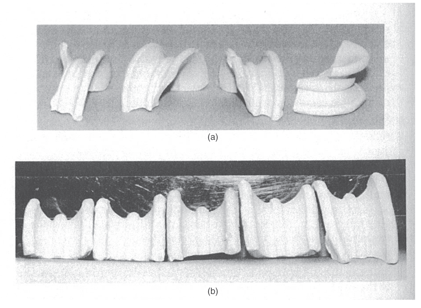
Column diameter (ft)
Acceptable ring width (in.)
Excessive ring width (in.)
4
1¼″
1⅝″
6
1⅞″
2⅜″
8
2½″
3¼″
10
3⅛″
4″
12
3¾″
4¾″
10.2.3 Removal of Existing Trays and Packings
10.2.4 Tray Installation
10.2.5 Dry versus Wet Random Packing Installation
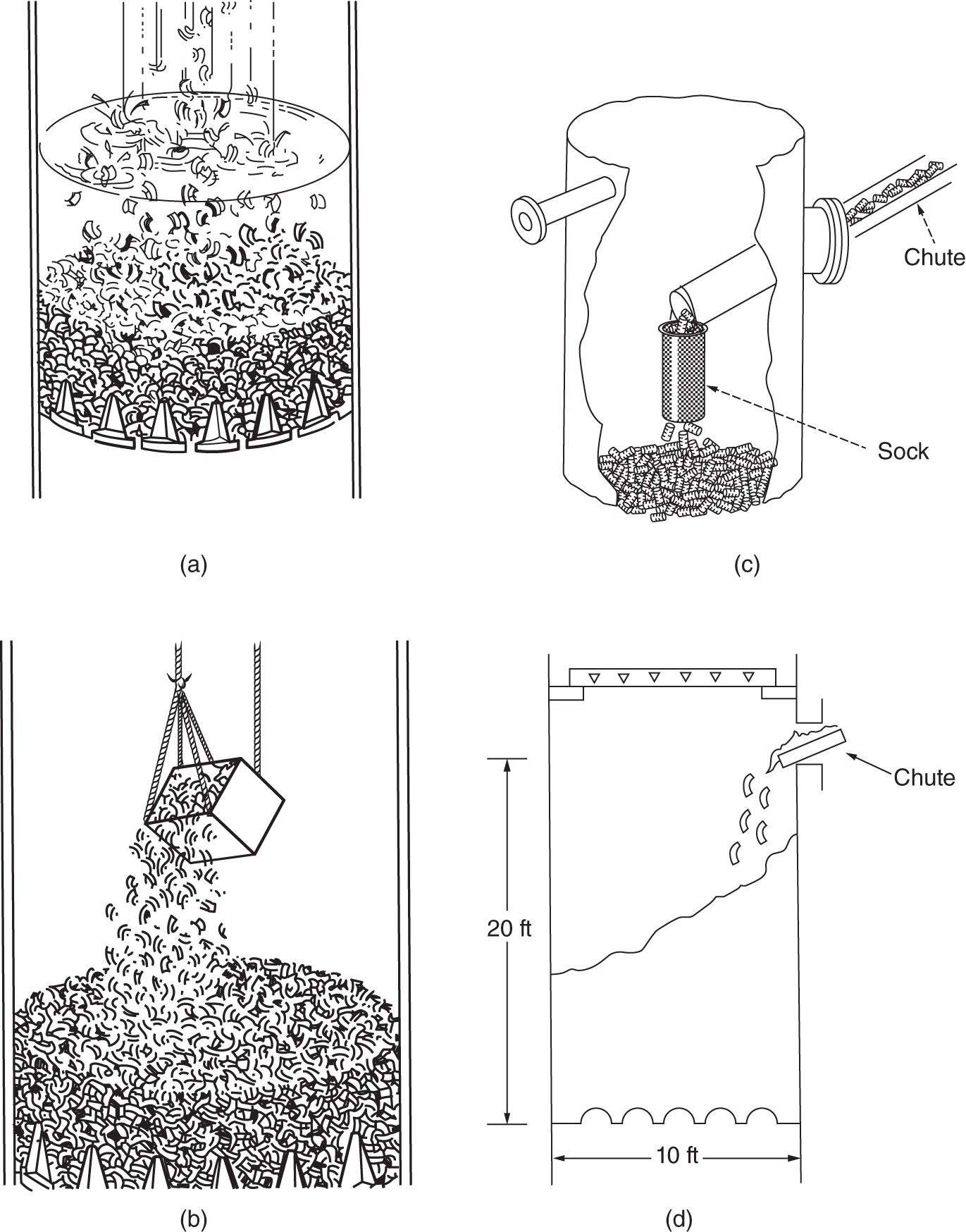
10.2.6 Dos and Don’ts for Random Packing Installation
10.2.7 Dos and Don’ts for Structured Packing Installation
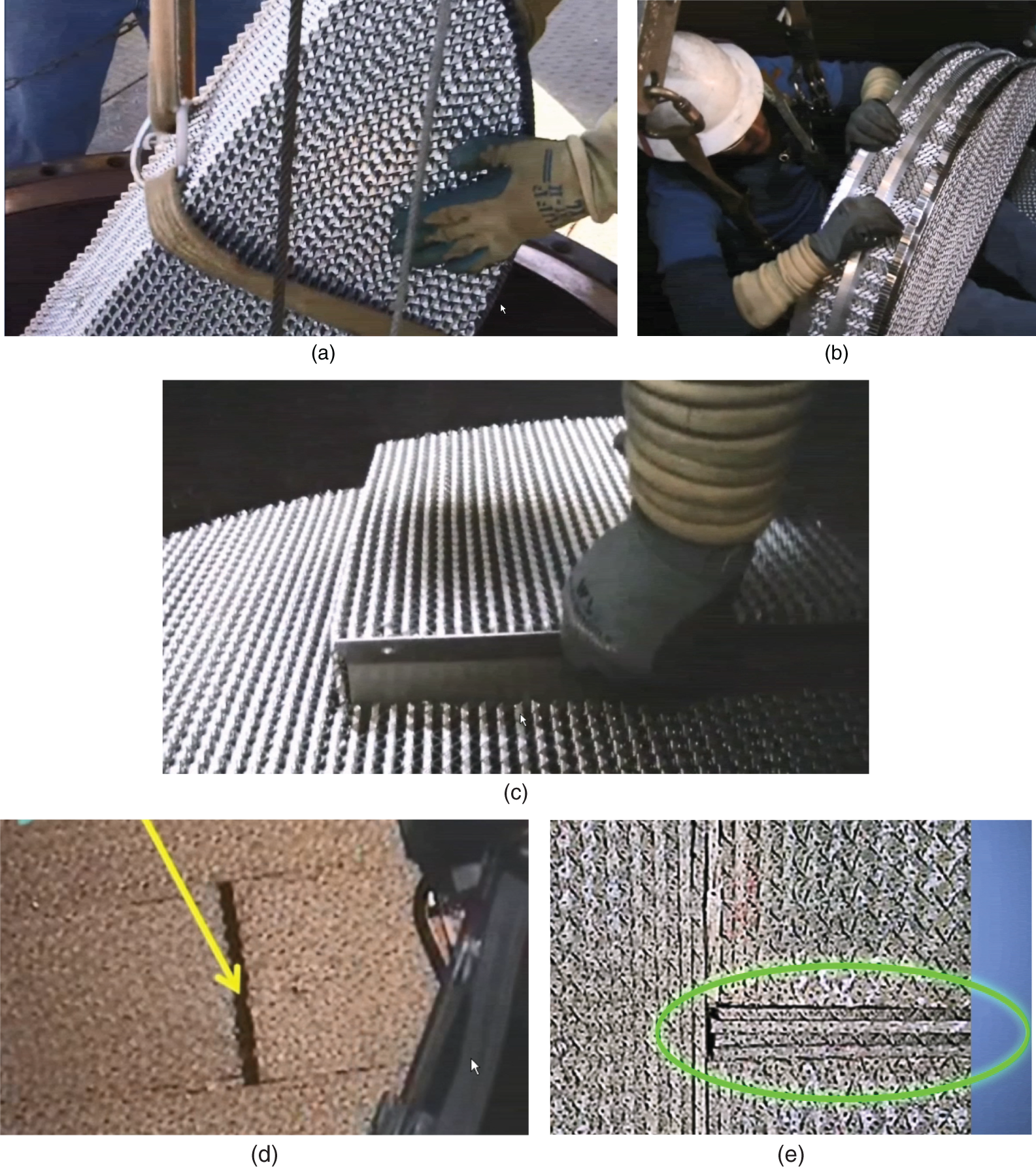
10.2.8 Some Considerations for Towers Out of Service for a Time
10.3 TOWER INSPECTION: WHAT TO LOOK FOR
10.3.1 Strategy
10.3.2 Should the Tower be Entered at the Turnaround?
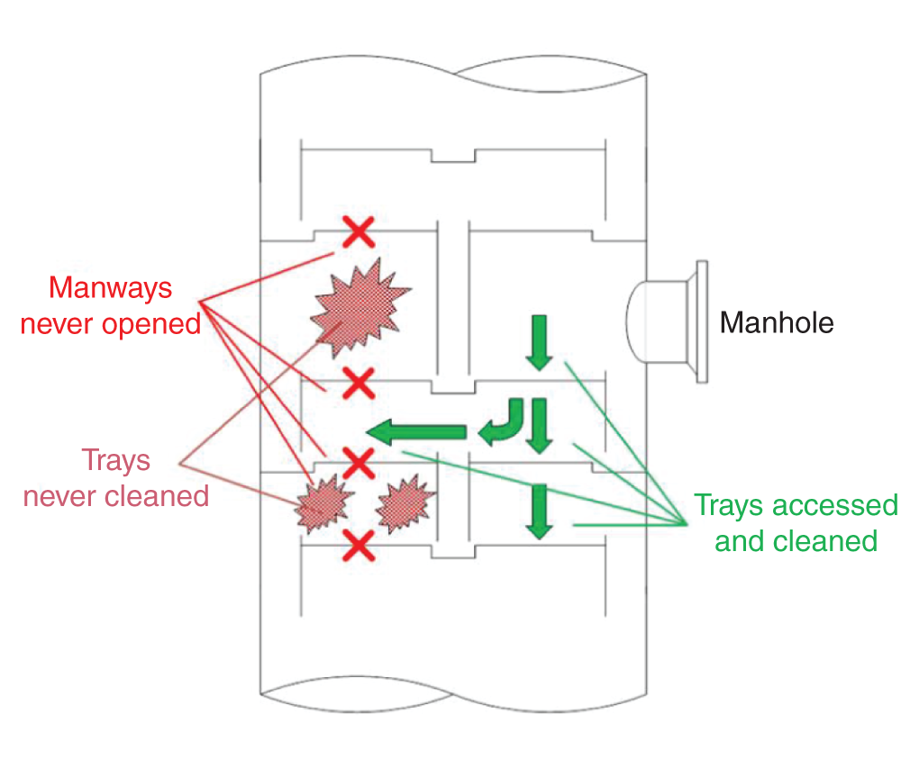
10.3.3 Inspector’s Checklist
Cases
1.
Packing liquid distributors
13
2.
Packing assembly
13
3.
Untightened nuts, bolts, clamps
9
4.
Tray panel assembly
8
5.
Feed/draws obstruction, misorientation
7
6.
Leaking collectors, low liquid load trays
7
7.
Downcomer clearances
5
8.
Debris left in column
5
9.
Unbolted tray manways
4
10.
Materials of construction
4
Column
Inspector
Date
Tray no.
Top
Bottom
Design
1
2
3
4
5
6
7
8
9
10
Value ± Tolerance
Points of transition
Orientation of internals
Passage obstructions
Possible impingement
Watermarks
Instrument location
Chimney trays
Riser-hat clearance
Riser diameter
Riser number
Hats correctly mounted
Flow obstruction to outlet(s)
Unintended liquid descent
Hats strong, supported?
Vapor rise obstruction
Vapor impingement
Buckling, riser bow
Instrument taps
Trays
Downcomer clearance
Weir height
Downcomer width
Downcomer brackets/bow
Hole diameter
No. of holes/valves
Valve direction
Light/heavy valve arrangement
Panel alignment/overlap
Valves secure?
Cracks and crevices
Holes/valves under downcomers
Tray levelness
Tray spacing
Tray/downcomer materials
Trays/downcomers secure
General
Deposits found? Sampled?
Corrosion found?
Bolting firm?
Double nutting?
Fastening materials
Gaskets
Absence of debris
Damage: bow, warp, cracked
Unexpected features
Sumps
Inlet weir/seal pan width
Inlet weir/seal pan depth
Weep hole area
Weep hole diameter
Gaskets: tightness
Others
10.3.4 Packing Distributor Checks
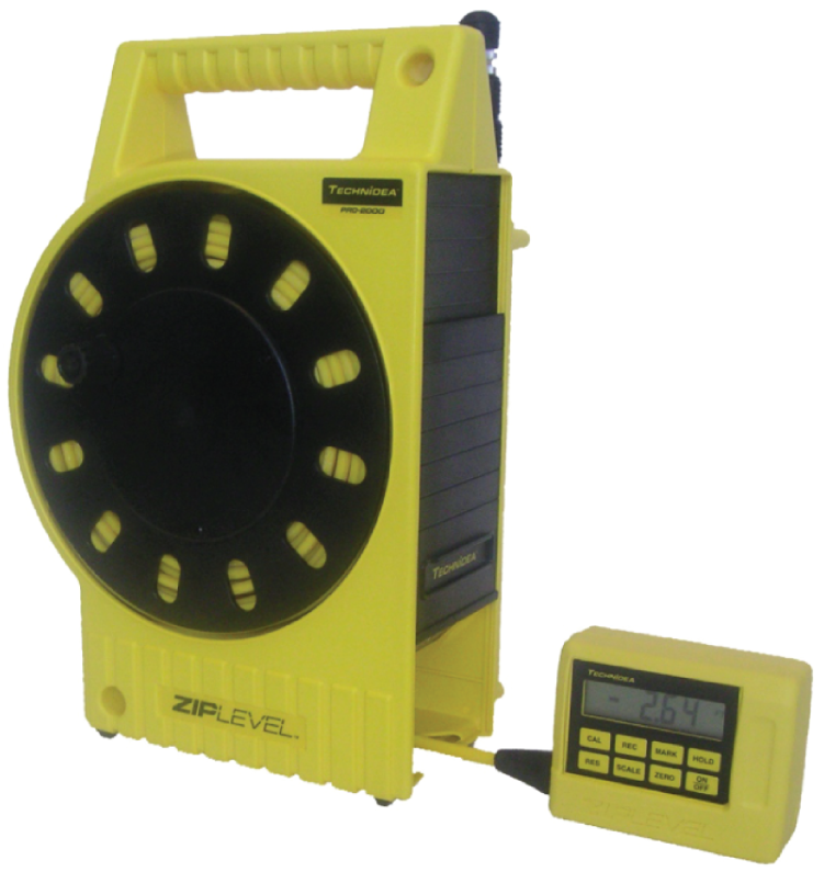
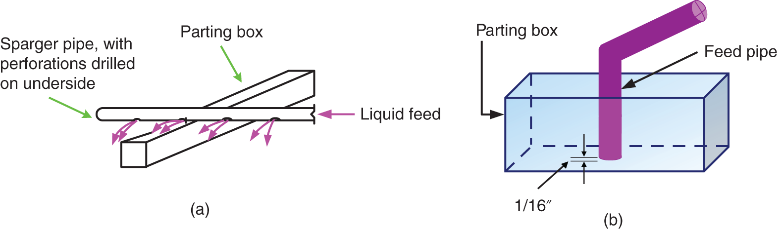
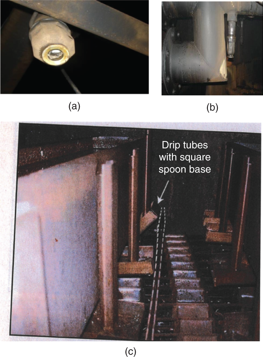
10.3.5 Packing Assembly Checks – Existing Columns
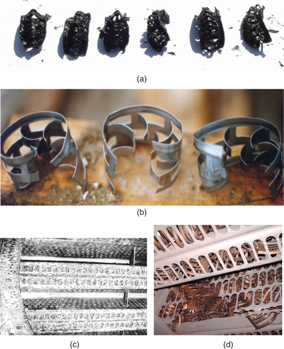
10.3.6 Untightened Nuts, Bolts, Clamps, and Downcomer Panel Assembly
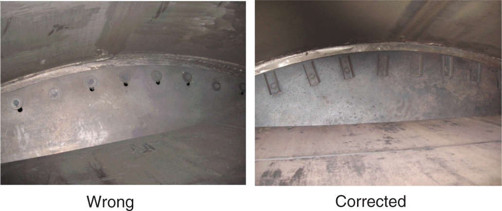
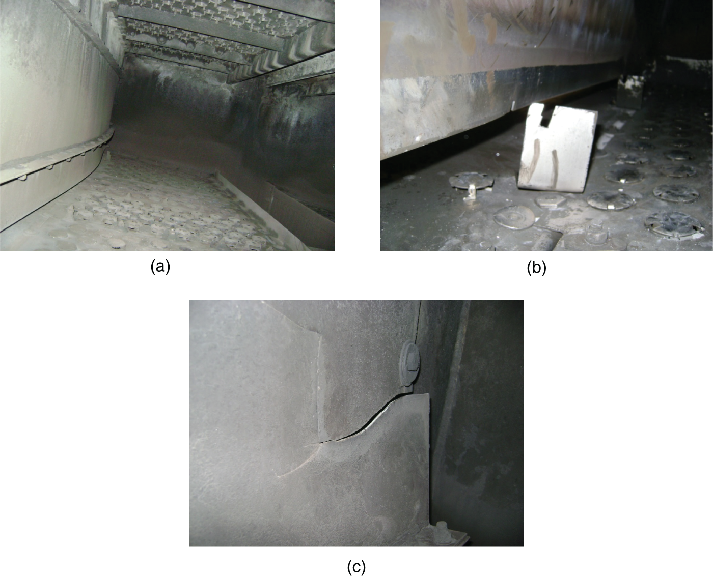
10.3.7 Tray Assembly
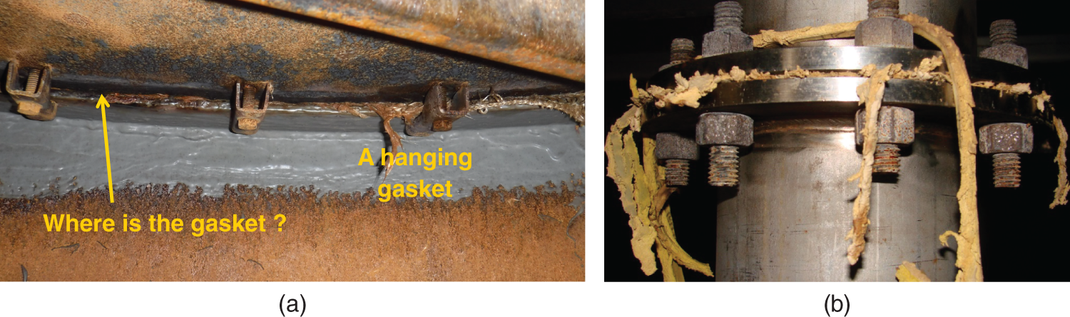
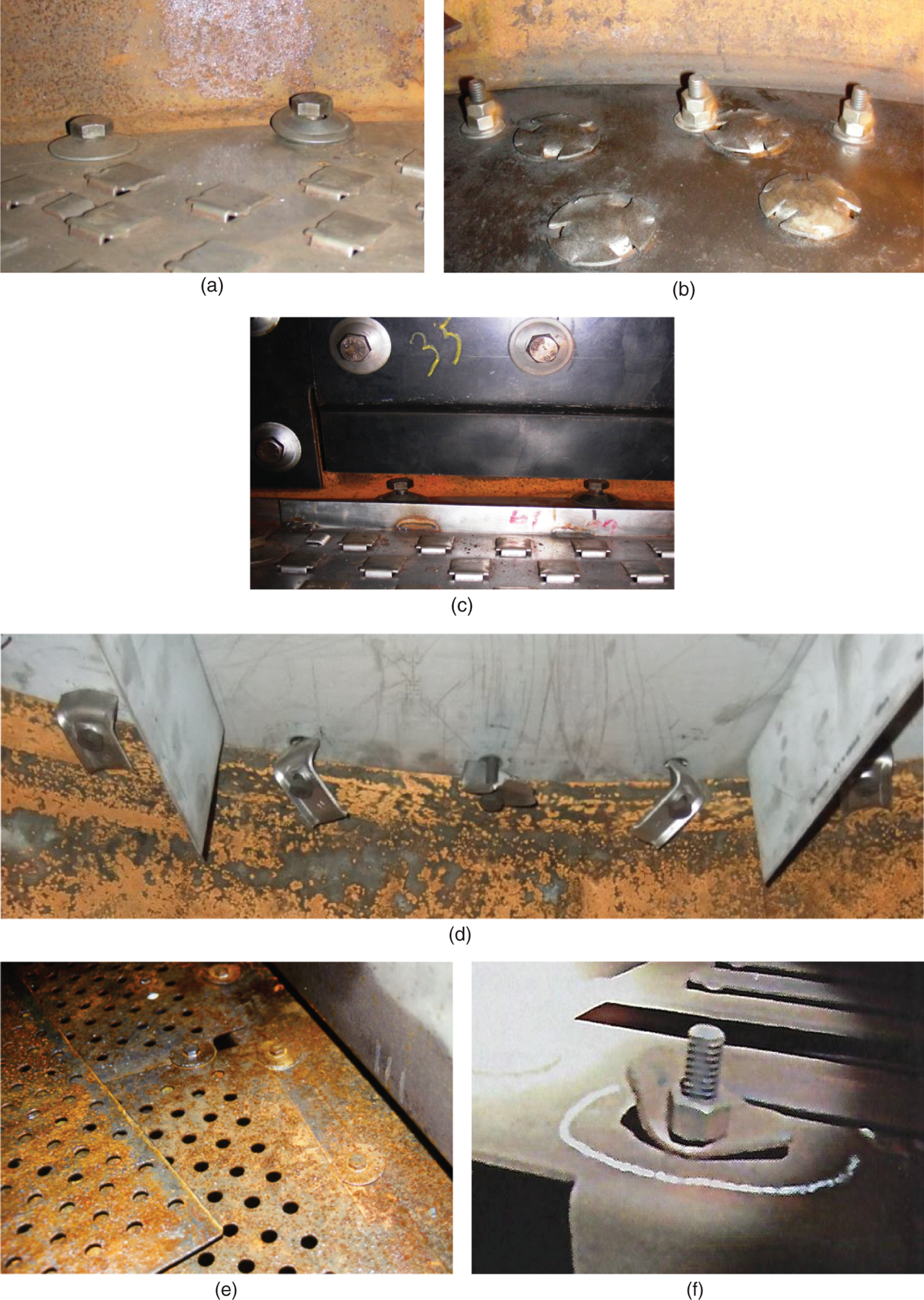
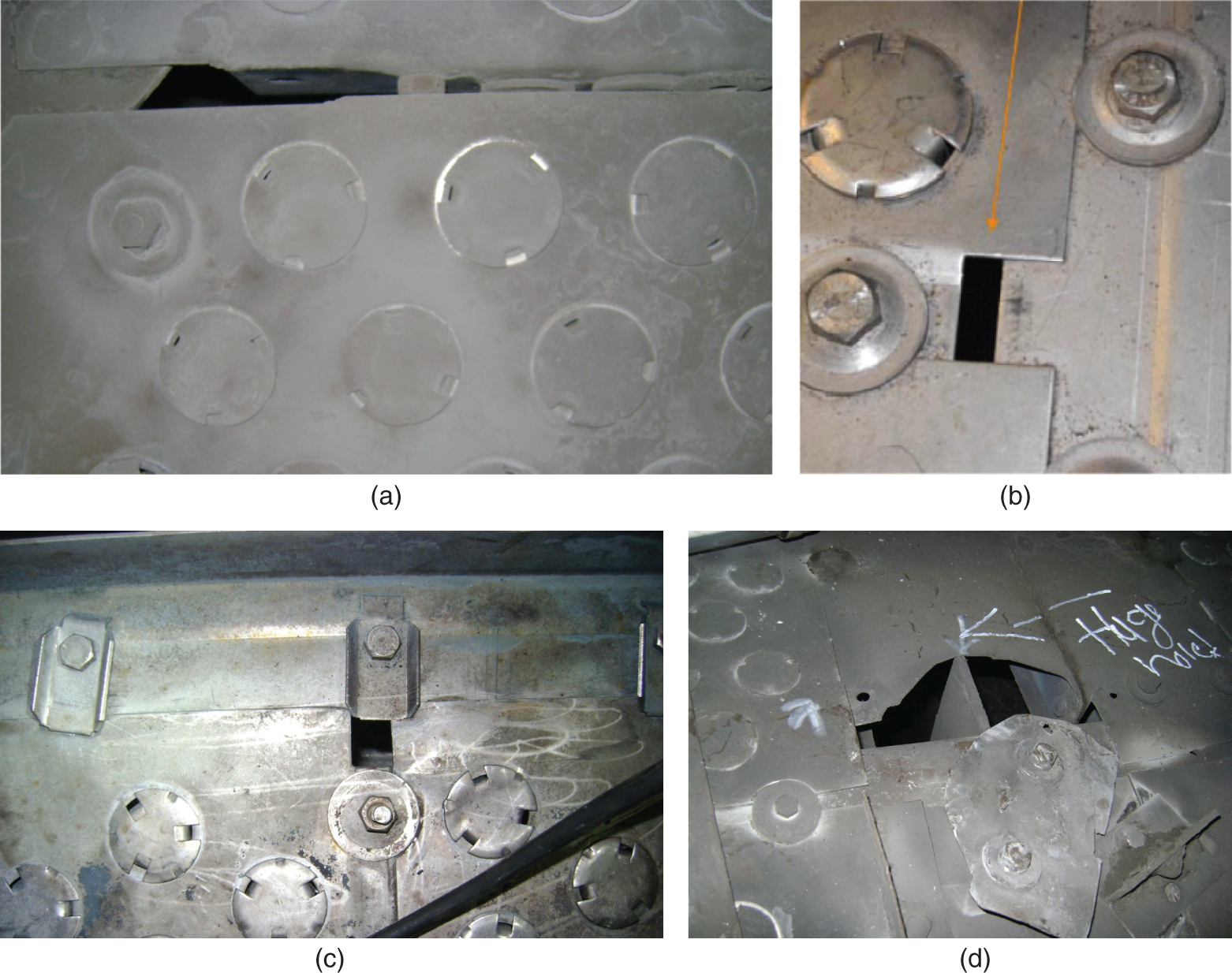
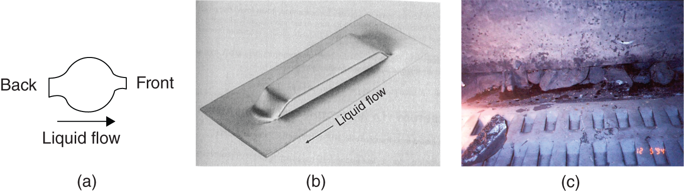
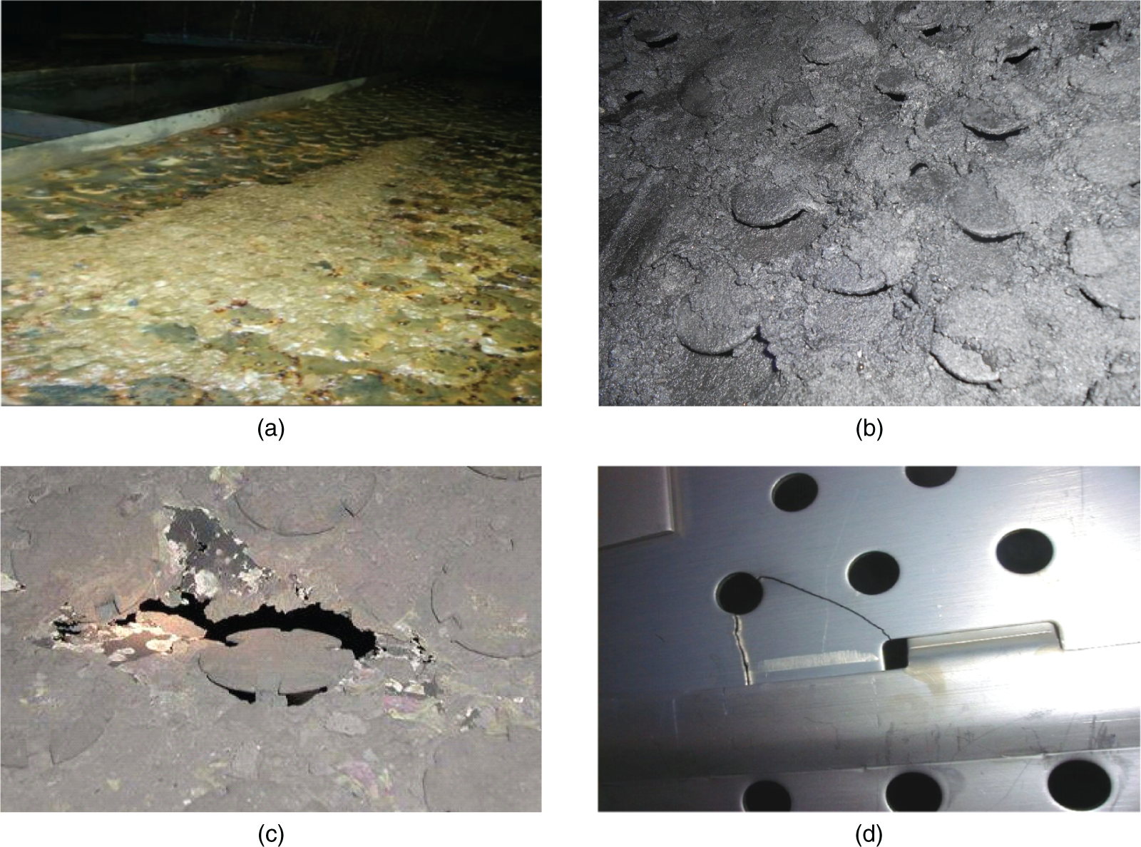
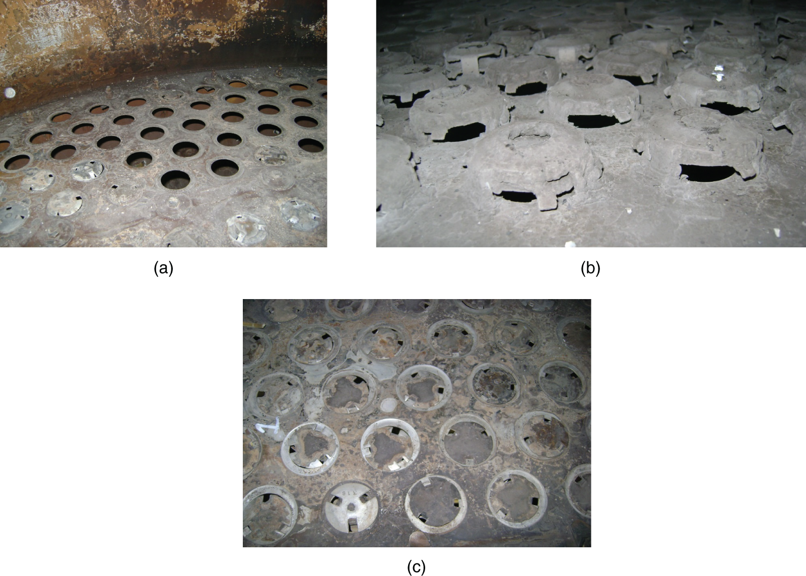
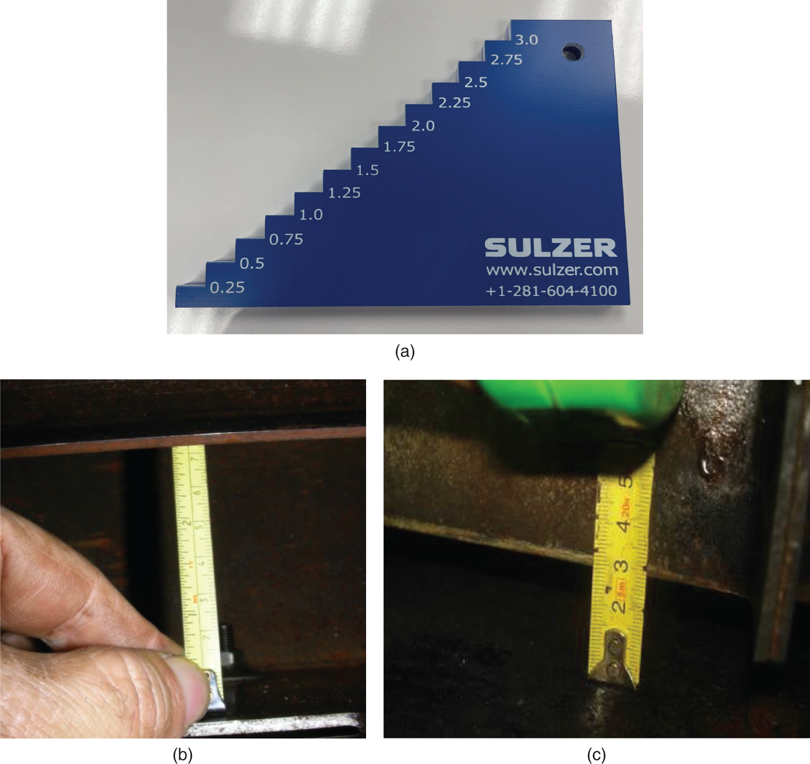
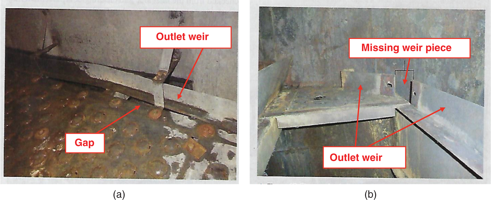
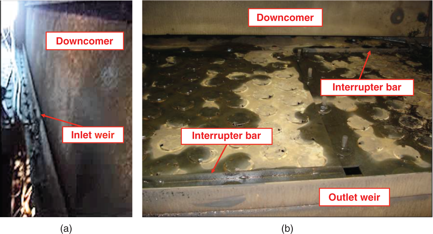
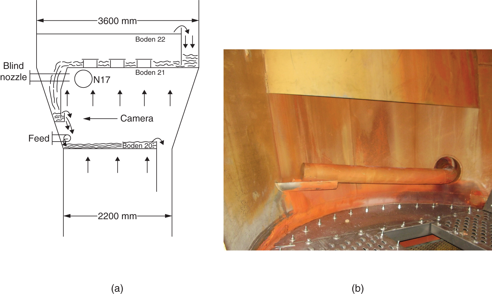
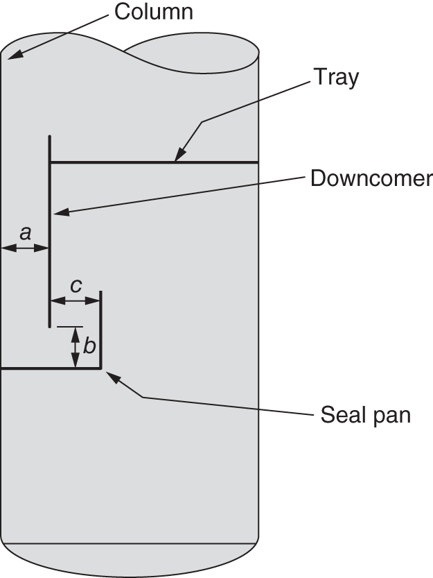
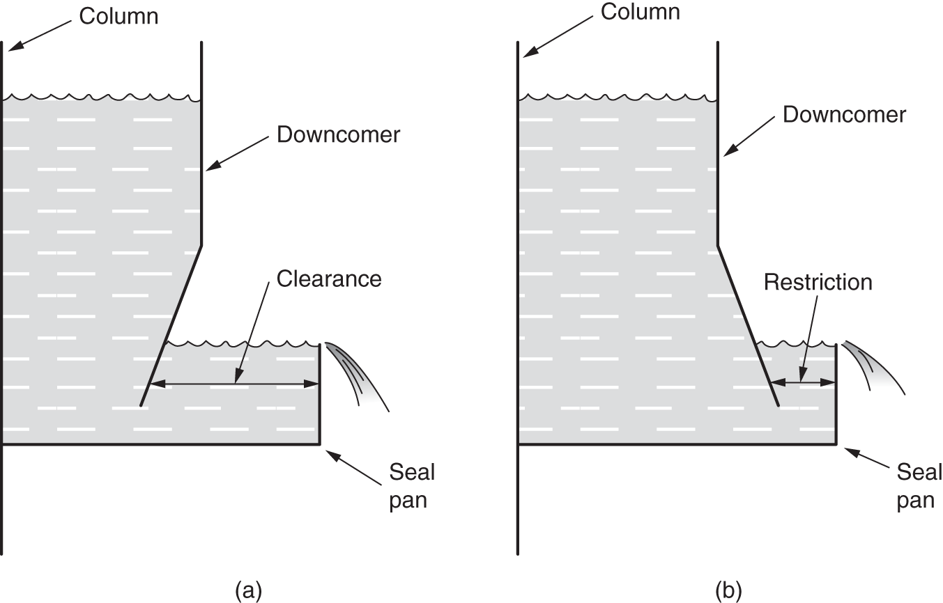
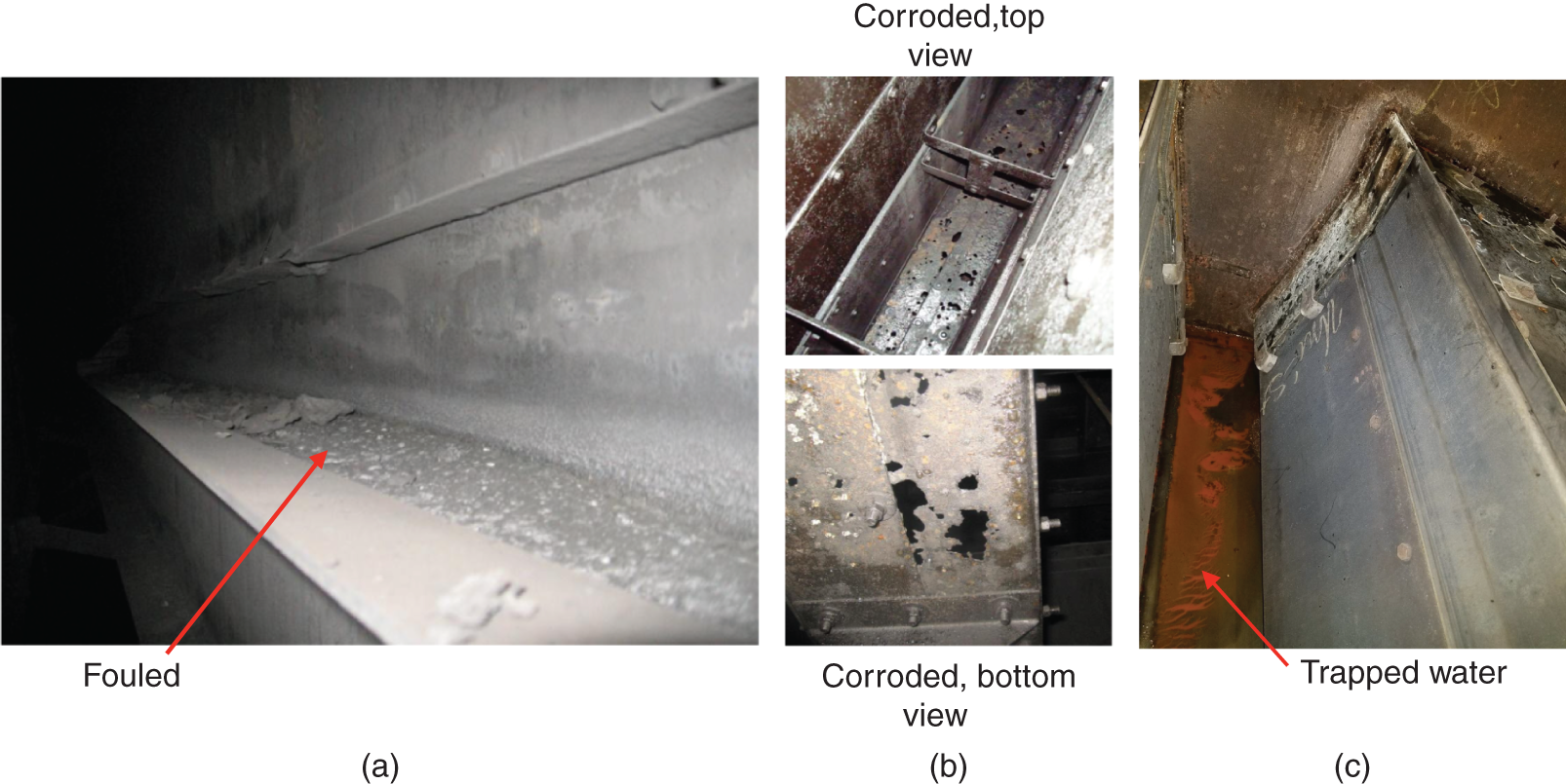
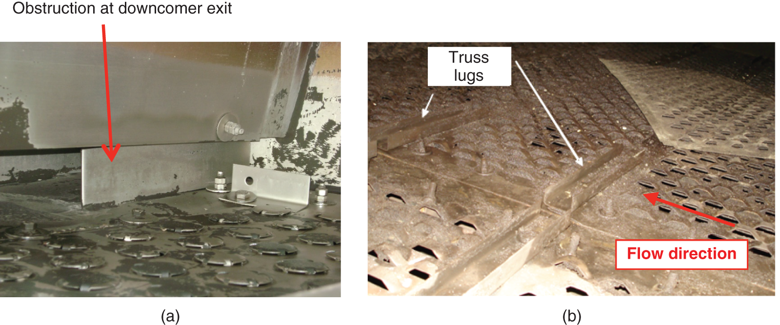
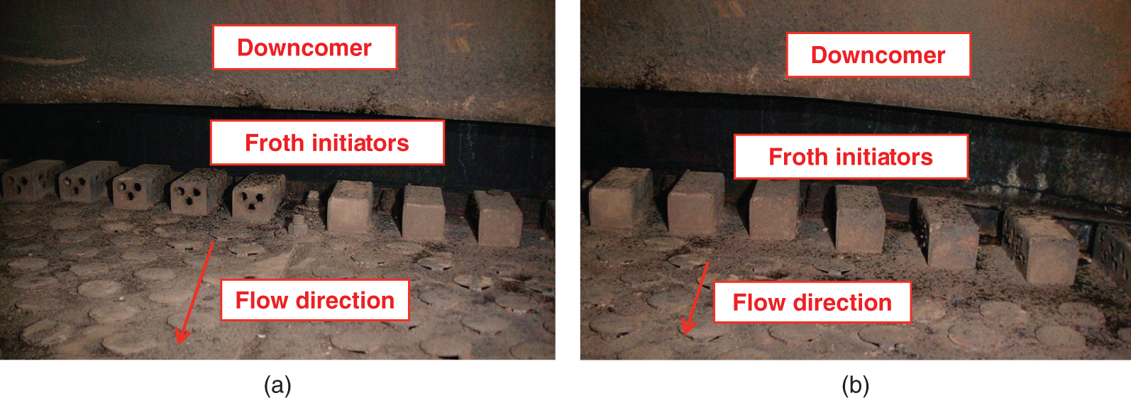
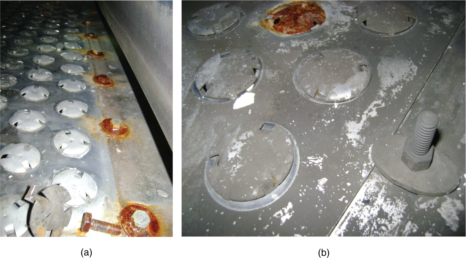
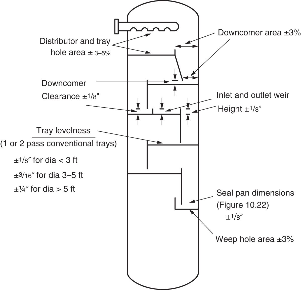
10.3.8 Feeds/Draws Obstruction, Misorientation, and Poor Assembly
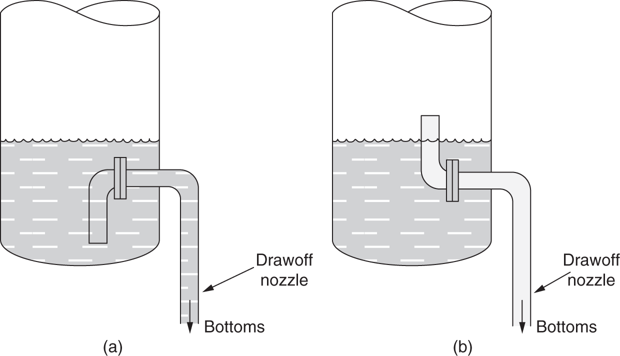
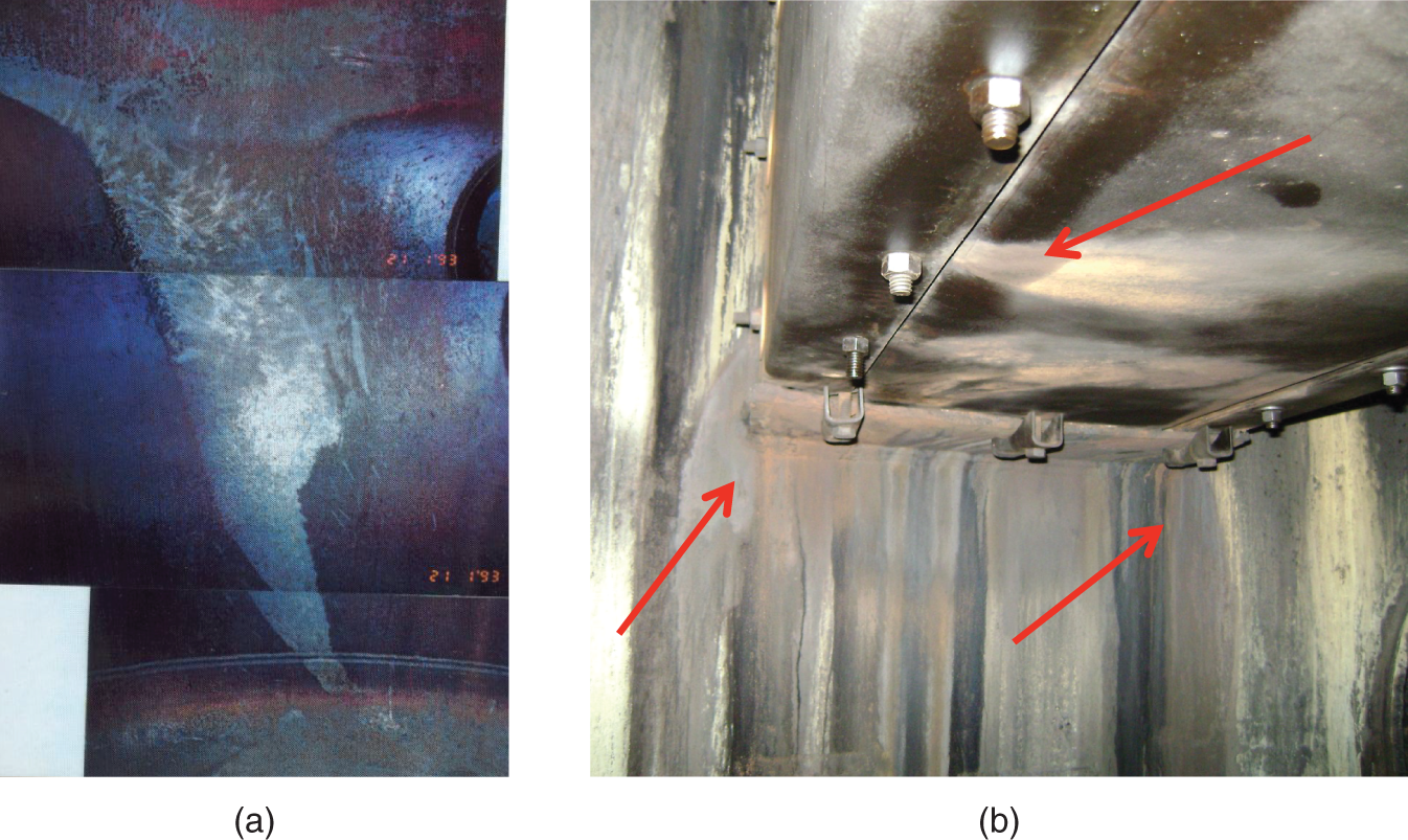
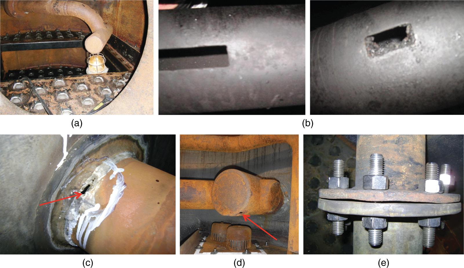
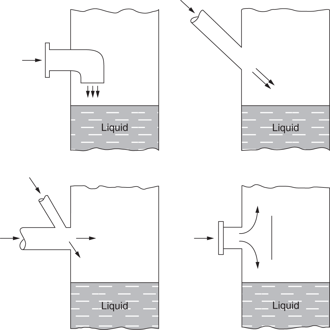
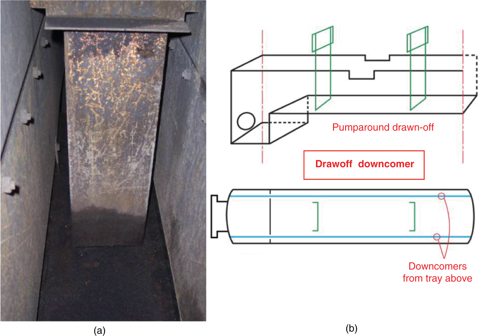
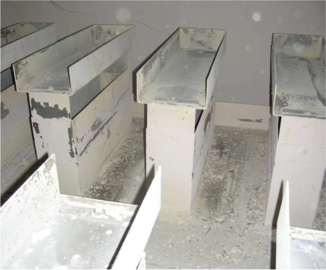
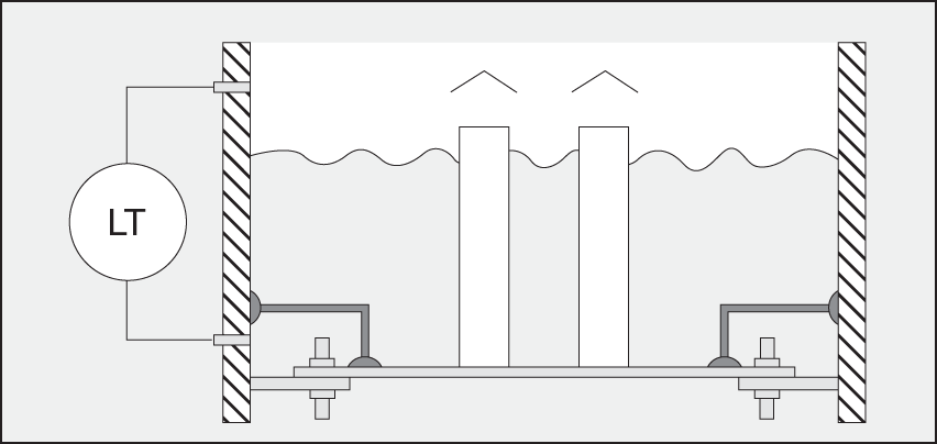
10.3.9 Cleanliness of Internals
10.3.10 Final Inspection
10.3.11 Externals Inspection