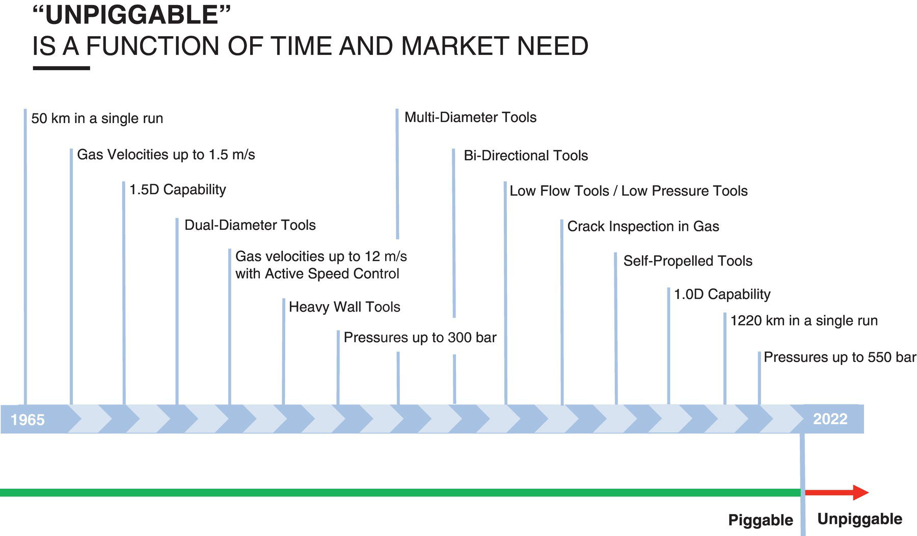
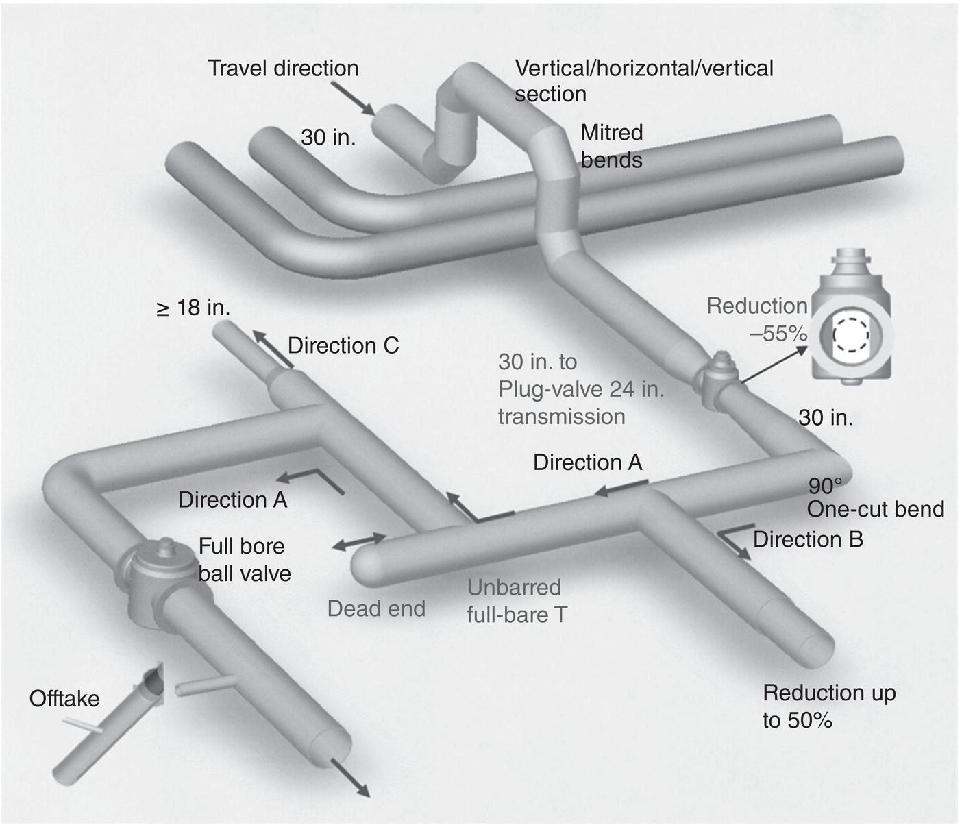
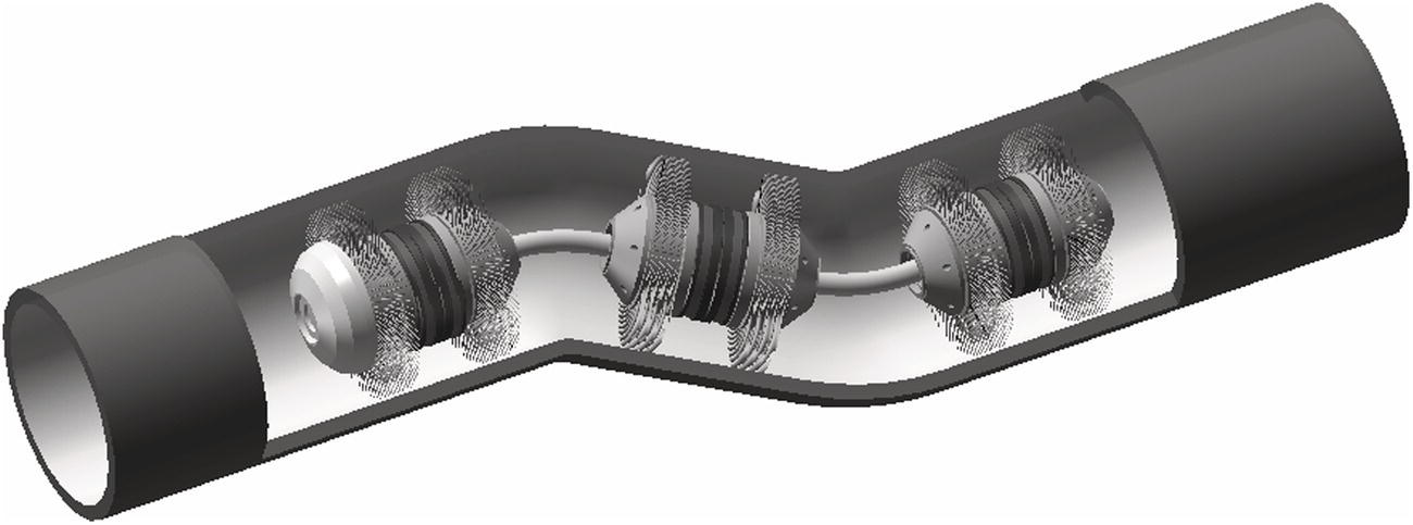
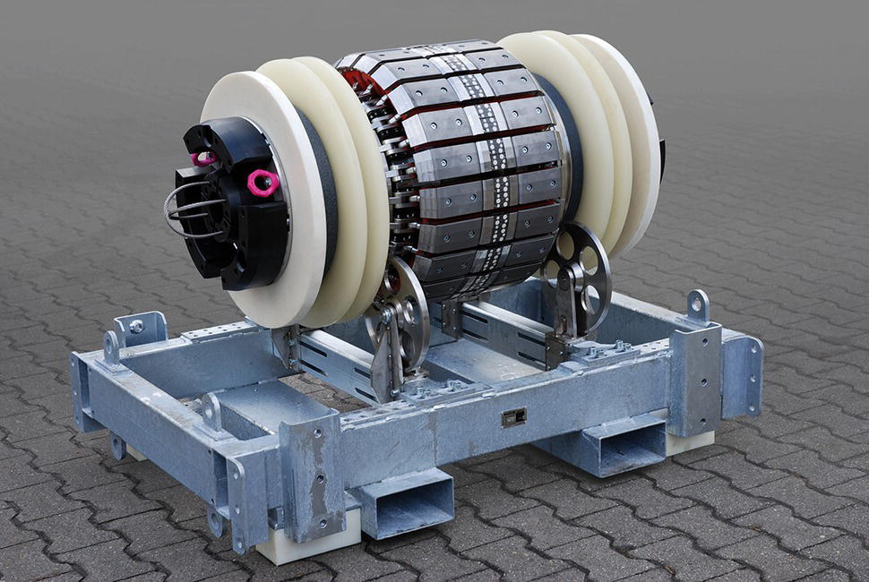
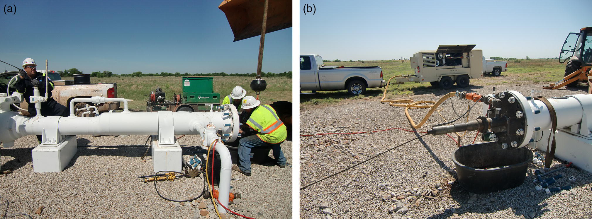
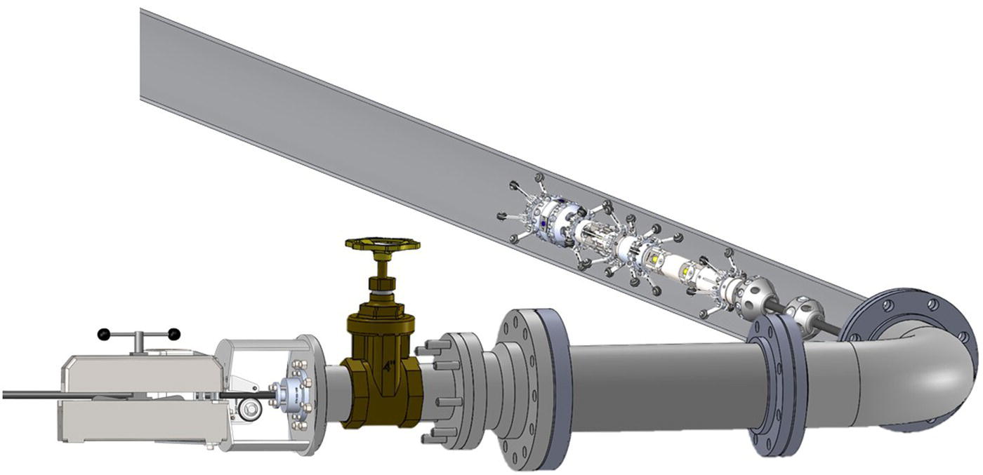
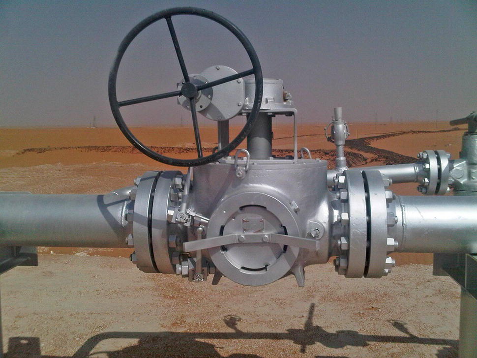
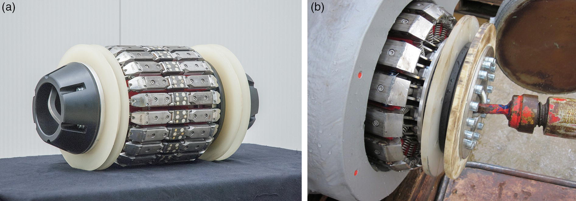
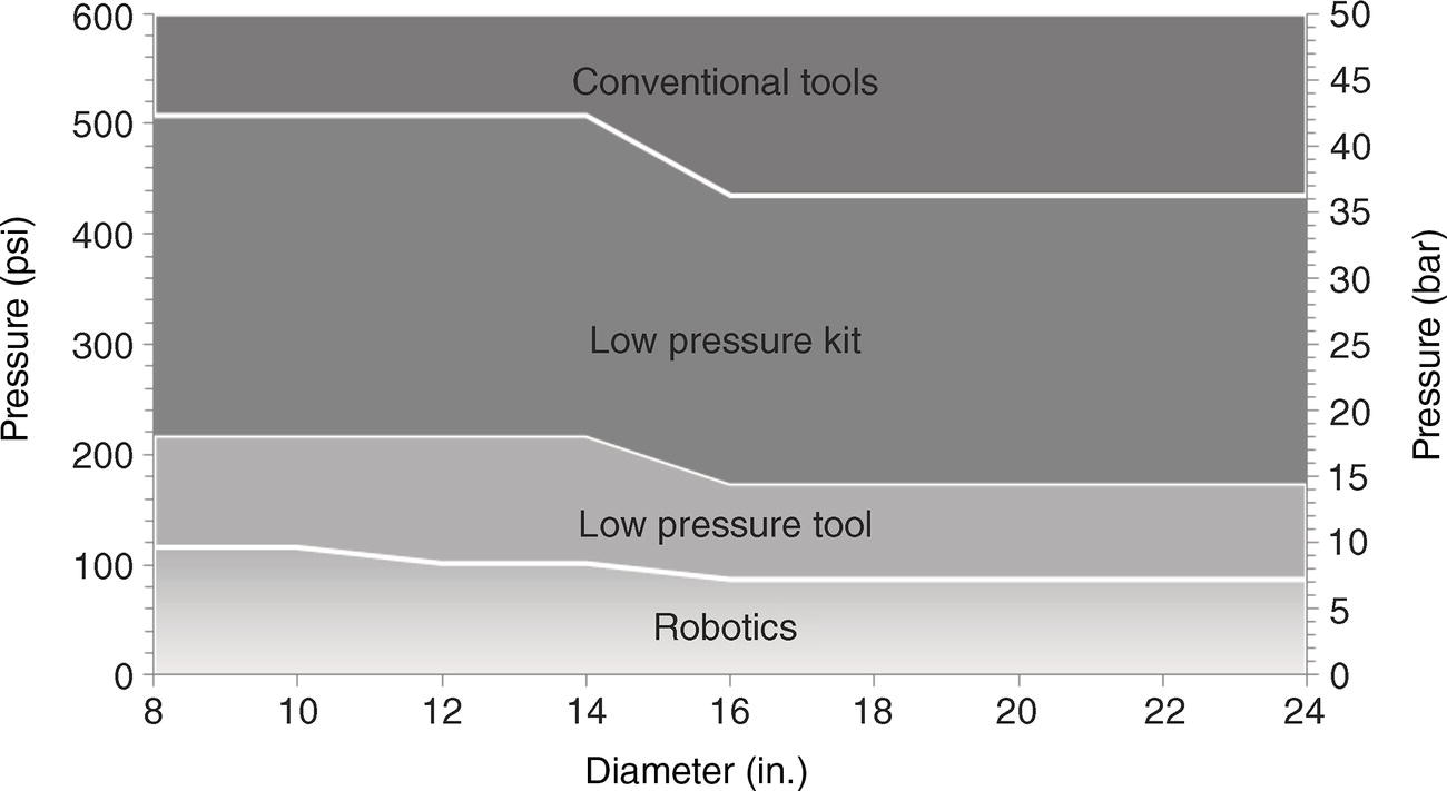
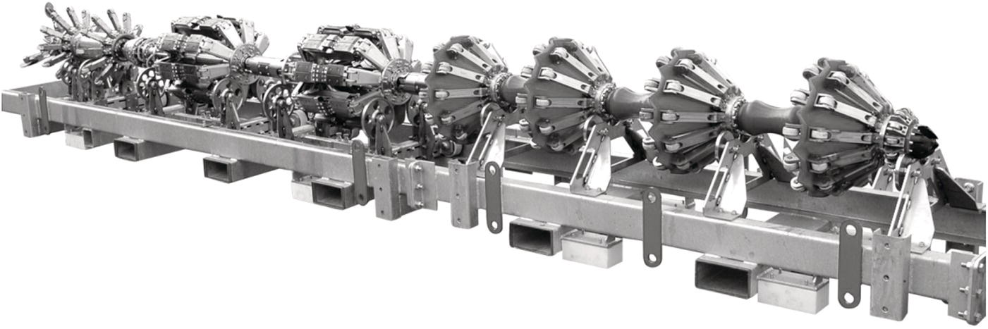
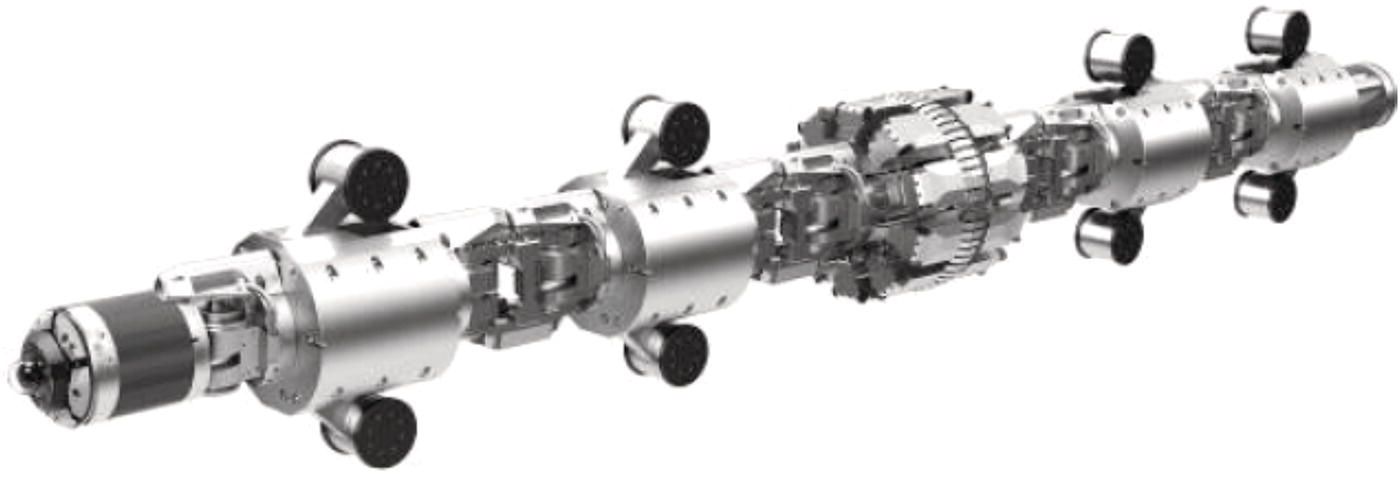
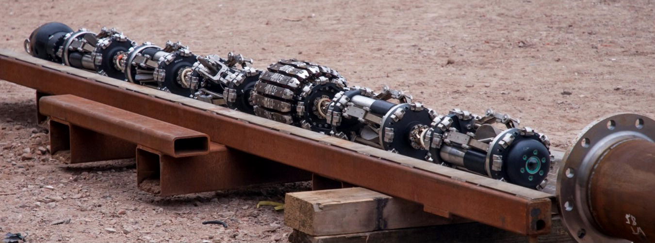
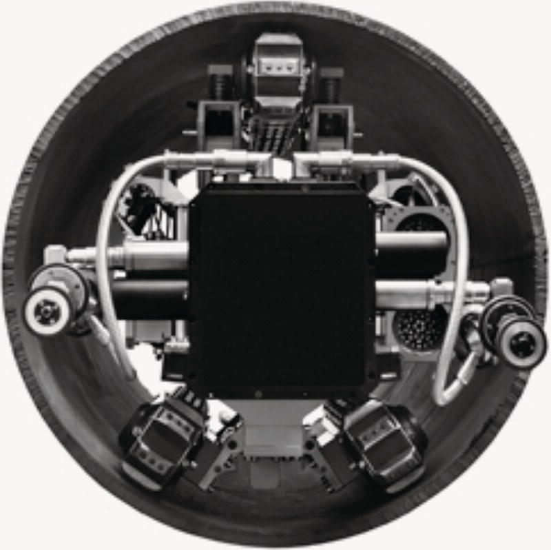
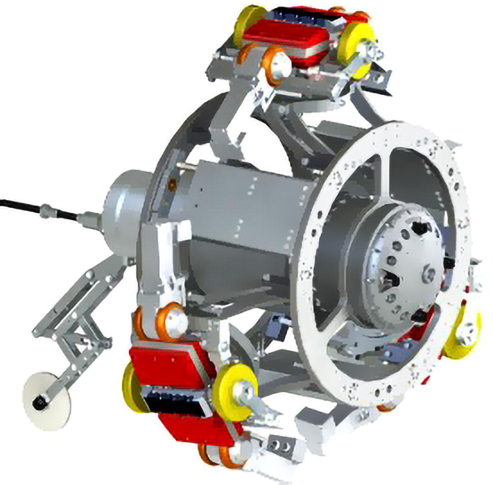
Tom Steinvoorte ROSEN Europe B.V., Oldenzaal, The Netherlands Pipelines have been proven to be the safest way to transport and distribute gaseous and liquid hydrocarbons. Regular inspection is required to maintain that reputation. Today, a large part of pipeline systems can be inspected with “standard” in-line inspection (ILI) tools. Since first use in the early 1960s, ILI tools have been developed and improved significantly. Challenges of the early days of pipeline inspection, such as high speed in gas lines, tight 1.5D bends, dual diameter, heavy wall thickness, high pressure and temperature, multidiameter, and long distances, have been resolved, and modern ILI tools are able to cope with these challenges. Figure 33.1 shows the “unpiggable timeline.” It is believed that, to date, still up to 40% of the world’s oil and gas pipelines cannot be inspected with existing tools and procedures, and as mentioned previously, reasons why pipelines are classified as unpiggable are numerous. To operators, these unpiggable pipelines are equally important to the overall integrity of the pipeline system; suitable inspection solutions are therefore required. Although alternatives such as direct assessment and spot checks using in-field, nondestructive testing exist, the most valuable information can only be obtained from the inside of the pipeline using ILI devices. This chapter will discuss the definition of an unpiggable pipeline, the challenges related to their inspection, ways of making unpiggable pipelines piggable, recent technology advances, and the process of selecting a suitable inspection solution. As a result of the increasing focus on the inspection of these unpiggable pipelines, many case studies and contributions have been presented at industry conferences and seminars. Although the word “unpiggable” does not exist in dictionaries, the word is frequently used in the pipeline industry. The word “unpiggable” is typically used for pipelines that do not allow an ILI tool to be run from start to finish. In the process of identifying a solution for an unpiggable pipeline, it first has to be identified why the pipeline is considered “unpiggable.” The reasons why pipelines cannot be pigged are numerous but can be categorized as follows: A prerequisite to an ILI is that ILI tools can enter and exit the pipeline. Conventional inspection approaches require launchers and receivers that enable ILI tools to access and exit the pipelines. The pipeline contains installations, such as plug valves, 90° miter bends, dead ends, and off-takes, that cannot be passed with conventional ILI tools. Figure 33.2 shows typical challenges. The pressure and/or flow in the pipeline is not sufficient, or too high, to propel the ILI tool through the pipeline within its specified operating velocity. Aggressive media may also pose a challenge for the ILI tool to navigate the pipeline. Not only the individual categories but also the combination of these have to be considered. For example, for multidiameter, low-flow and thick-wall gas pipelines, magnetic flux leakage (MFL) tools are available. The combination of the three challenges may, however, require the development of a new ILI tool—or inspection may perhaps not even be possible at all. Figure 33.1 Unpiggable timeline. Figure 33.2 Unpiggable installations. In the recent past, there has been an increasing focus on providing solutions for the population of these unpiggable pipelines, and it has been recognized that the word “unpiggable” is not appropriate. Any unpiggable pipeline can be transformed into a piggable pipeline by modification of the pipeline and/or its operating conditions; if there are no traps, they can be installed; if a pipeline is considered unpiggable due to, for example, a one-cut 90° miter bend, it can be changed out; unfavorable operating conditions can be adjusted to the needs of the inspection tools. The pigging of one pipeline may just require more effort and investment than that of another. Therefore, the industry now refers to these pipelines as “challenging” or “difficult to pig” rather than “unpiggable.” In principle, there is even a difference between “difficult to pig” and “difficult to inspect.” For example, a foam pig might still be able to pass a special miter bend, but the same might be impossible for a hard-body pig. As already discussed, the development of solutions for unpiggable pipelines is a function of time and market need. In response to increasing demand, ILI vendors have developed and will continue to develop innovative solutions and procedures for the inspection of challenging pipelines. A challenging pipeline inspection today can be a standard pipeline inspection tomorrow. Considering the aforementioned contributing aspects, we now come to the definition: a pipeline is defined as “unpiggable” or “challenging” if inspection with current conventional technologies and procedures is considered not feasible. Contrary to piggable pipelines, challenging pipelines often were not designed to be pigged. In addition, documentation is often incomplete or not available at all. Pre-inspection cleaning and gauging may not be possible either, so important questions related to bore restrictions and cleanliness are left unanswered. Consequentially, these unknown conditions need to be considered in the overall inspection approach. Not designed to be pigged often means that there is no access point available for a tool to enter/exit the pipeline. Temporary or permanent traps or (modified) spool pieces can be considered. Just a pipeline opening in explosion-safe conditions may already be sufficient for self-propelled solutions, for example. Modifications often require the pipeline to be taken out of service. Not only the pipeline modification itself but also the consequence of the pipeline taken out of service (e.g., production deferment) must be considered. The selection of a suitable inspection technology does not depend on the objective of the inspection alone; the conditions of the pipeline must be considered, as well, as the technology may have to cope with the (often unknown) conditions in the pipeline. Especially for self-propelled solutions, friction forces and power consumption must also be considered. Even if the tool can move in the pipeline, the recorded data might be not satisfying because of too much wax and/or debris in the line. Once a suitable technology has been selected, this technology has to be brought to the pipe wall, where it needs to do its intended job. Conventional pigging uses the medium to propel the tool/technology. When this is not feasible, other solutions, such as tethers or crawlers, have to be considered. A clean pipeline is a prerequisite for successful inspection of a challenging pipeline for several reasons. To achieve optimum measuring results, inspection tools require a fairly clean pipe surface for MFL, electromagnetic acoustic transducer technology (EMAT), eddy current (EC), and remote field eddy current (RFEC); a clean surface is needed for ultrasonic testing (UT). Because debris may also influence the run behavior of the ILI tool, it can potentially affect data quality (e.g., speed excursions in low-flow or low-pressure gas pipelines). Larger amounts of (unexpected) debris might even prevent the tool from reaching the end of the pipeline (the tool becomes lodged). Whereas the risks associated with running conventional ILI tools are well-understood and accepted, this is not necessarily the case for unconventional inspection solutions. Although operators often would like to use the most recent and advanced technologies, they often hesitate “to be first.” Also, the question, “What if the system fails?” has to be answered, and well-designed failsafe mechanisms have to be in place in case the risk of a tool being lodged in a pipeline cannot be accepted. Extensive testing may also be required to demonstrate the system’s capability in a controlled environment. One of the biggest challenges with difficult-to-inspect pipelines is the unique combination of the specific factors that make each particular pipeline an inspection challenge. As with every pipeline inspection, the first step is to complete the pipeline questionnaire. Additional information—for example, configuration of bends, elevation profile, the possibility to change operation conditions, or to take the pipeline out of service—is typically required to support the selection process. Figure 33.3 Challenging pipeline inspection approach. (With permission of ROSEN Group.) Once the objective of the inspection is known, the challenges are identified, and the boundary conditions are known, there are various options that need to be considered to prepare for the actual inspection. Figure 33.3 shows the basic approach. To inspect an unpiggable pipeline from the inside, the first step that should be considered is to modify the pipeline (e.g., creating flow or pressure, exchanging fittings or tight bends that prevent an ILI tool from passing, or installing pig traps). An alternative approach to inspecting lines with insufficient pressure or flow, or for pipelines that do not have traps, is to pull an ILI tool through the line by using a cable and winch. This requires the pipeline to be taken out of service and can only be used for shorter sections of the pipeline. Vendors specify an inspection-length capability of up to 2.5 mi (4 km), but the presence of bends significantly reduces the practical distance that can be covered. This is the case especially for the MFL technology because of the drag resulting from the magnets. Individual capabilities depend on the amount, location, orientation, and radius of bends; the friction force of the selected technology in the pipeline; the total length to be inspected; and the amount of debris expected; a detailed assessment is required. A cable-operated inspection approach can be used both unidirectionally and bidirectionally. For a bidirectional application, the tools can be pumped in with, for example, air and pulled back via the cable. A further alternative is a self-propelled tool, which is described in Section 33.2.4. Cable-operated inspection is also commonly referred to as wire line inspection. If a pipeline modification is not feasible for the intended application, then the next step is to assess the feasibility of modifying an existing tool. Examples include multidiameter tools, bidirectional tools, and low-friction tools that are capable of inspecting low-pressure gas pipelines. Section 33.4 provides an overview of recent developments in ILI tools. If the inspection of these pipelines is not feasible with a free-swimming or cabled inspection tool, even after modification of piping or tools, then self-propelled solutions are required, which can also be free-swimming or tethered. In this case, running pre-inspection cleaning and gauging tools is typically not possible. As a part of the inspection approach, the cleanliness of the pipeline has to be considered, and alternative cleaning solutions may be required. High-speed flushing with, for example, diesel to dissolve paraffin or to remove sediments can be considered. Hydro-jetting may be possible, as well. In some cases, hard encrustations can be broken out with the tethered ILI tool itself and then flushed away. In case upfront cleaning is not possible, the inspection solution has to cope with a certain amount of debris; inspection without cleaning. Other challenges relate to the geometry of the pipeline as well as the operational conditions during the inspection. Slippery surfaces may affect the traction of drive wheels, inclination, wall thickness changes, bends, and offtakes need to be considered as well. Due to the variety of challenges, the optimal solution for unpiggable pipelines often is not a single tool but rather a project-by-project-driven tailored solution. A detailed upfront assessment is required to identify the specific conditions the inspection device is expected to encounter. The unique nature of the specific factors that make each individual pipeline an inspection challenge often requires a solution tailored to the specific needs. A wide range of solutions is necessary to satisfy the market’s needs, but pigging vendors often hesitate to invest in them because the application range for each of these solutions might be limited. Self-propelled solutions are available, but the specific requirements nevertheless limit each application to a smaller group of pipelines matching the conditions required for these solutions. Section 33.4 provides an overview of available solutions. Once one or more suitable inspection solutions are identified, the most suitable approach has to be selected. Aspects to consider in the selection process include Since the early days of pigging, ILI tools have been developed and improved significantly. This chapter will discuss several of the more recent developments in ILI tools. For those pipelines that only have access from one end, special bidirectional ILI tools have been developed. Geometry, circumferential MFL (CMFL), UT wall thickness measurement (UT WM), EMAT, and UT crack detection (UT CD) tools are readily available (see Figures 33.4–33.6 and also Ref. [4]). However, most of them are not yet available in all required diameters. This will depend on market demand. Figure 33.4 Bidirectional geometry tool. Figure 3 in “Multidisciplinary Pipeline Inspection Project, development of in-line ultrasonic Inspection tool to be able to pass multiple mitre bends and 1D back to back bends in one inspection run,” by L.J. Gruitroij, A. Hak Industrial Services B.V., The Netherlands, © 2013 Pigging Products and Services Association. A. Hak is Intero Integrity today. (Reference [1]/with permission of Pigging Products and Services Association.) Figure 33.5 Bidirectional UT geometry and WM ILI tool. (Reference [2]/Quest Integrity Group.) Figure 33.6 Bidirectional MFL ILI tool. (Adapted from Ref. [3].) For pipelines requiring a bidirectional inspection, specific procedures have to be developed to bring the ILI tool to the end point and back to the entry point. The propulsion methods described below must be carefully reviewed on a project-by-project basis. If a propulsion method has been selected for the application of a bidirectional tool, procedures have to be developed to ensure the ILI tool traverses the entire section of the pipe to be inspected to achieve the inspection objectives. For a free-swimming bidirectional tool, the easiest way of navigating through a pipeline is by pumping the tool to the end point, stop it, and then reverse the flow in the pipeline system to propel the tool back to the launching facilities. If a parallel line is available, this can be done by simply connecting these via flexible hoses or by installing a temporary pump spread on the other side to push the product back in the opposite direction. Short sections of gas pipelines can be inspected by pushing the tool against the product pressure into the pipeline up to the end point. The remaining gas volume behind the tool is then used to send the tool back to the entry point by controlled pressure release at the launching facilities. For the inspection of vertical sections, a gravity-based approach can be used. In addition, the tool can be pushed down the pipeline using the hydrostatic pressure of a storage tank and pumped back by permanently available or temporarily installed pumps. Typical applications include loading lines and branch connections in storage tank farms. Another approach of deploying a bidirectional tool is to push the tool into the pipeline by using flow (e.g., nitrogen or air) and then recovering it by pulling it out using a winch and a cable. Figure 33.7 shows such a setup. Alternatively, a push–pull system with measurement equipment can be used when no flow can be created. The tool can be pushed for 60 m into a pipeline and pulled back without using a crawler or winch, as shown in Figure 33.8. Pipelines with a need for frequent maintenance cleaning are sometimes fitted with ball valves, which offer the option of launching a cleaning tool. Figure 33.9 shows such a valve. This kind of ball valve offers a cost-efficient solution because the pigging operation requires significantly less effort compared with cleaning using conventional pig traps. Figure 33.7 (a) Tool loading (left) and (b) launcher setup (right). (Adapted from Ref. [5].) Figure 33.8 Push–pull tool. (With permission of ROSEN Group.) Figure 33.9 Pig launch valve. (Reference [5]/with permission of ROSEN Group.) The cleaning tool is inserted into the valve while the valve is closed, and the door can be opened. After the door is closed, the valve is opened, and the tool is launched with the flow. The next downstream ball valve has the same functionality and is used as a receiver. At one end of the ball valve, a steel mesh is installed to stop the tool. The ball of the valve can be rotated by 360°; hence, it can be used as a launcher and receiver (not applicable to all pig valves). If only one valve is available, the cleaning can be done with a bidirectional cleaning tool. The tool is launched as described above. Once the end of the pipeline has been reached, the flow is reversed, and the tool is pumped back to the ball valve. If cleaning can be done only bidirectionally, ideally, the bidirectional cleaning pig should be designed such that the majority of the debris is removed and pushed out on the return (driving cup design: soft in, aggressive out). In the past, these ball valves have been used for cleaning only. With the new small and short bidirectional ILI tools, these lines can now also be inspected. MFL metal loss and geometry inspection services are available. Figure 33.10a shows a 10″ MFL tool, and Figure 33.10b shows the tool being inserted into the valve. The main challenge in inspecting low-pressure gas pipelines is speed excursions, which are usually caused by obstacles such as excessive girth welds, bends, dents, wall thickness changes, and debris. The tool stops at such an obstacle because the pressure (force) is not high enough to move the tool over it. After a certain time, the pressure behind the tool builds up and forces the tool over the obstacle. In some cases, tool speeds of over 67 mph (30 m/s) are reached, whereas most MFL ILI tools have a maximum speed specification of 11 mph (5 m/s). Furthermore, after the tool starts to move again, the head pressure in front of the tool is typically low; therefore, the high-speed phase is elongated. Additionally, excessive, uncontrolled speed excursions may even cause damage to the tool or the pipeline. Figure 33.10 (a) 10″ MFL tool for launch valve (left) and (b) tool loading (right). (Adapted from Ref. [5].) When exceeding the target tool speed, the magnetic field is affected in a way that makes it difficult to correctly size or even identify corrosion features. Furthermore, the resolution is impaired. To reduce speed excursions in low-pressure gas pipelines, conventional MFL tool performance can be improved by selecting a friction-reducing cup/disc configuration. Dedicated low-flow, low-pressure tools also feature friction-reducing magnetizers in combination with reduced tool length and weight. Figure 33.11 shows a selection guideline for low-pressure gas pipelines. With dedicated tools, pipelines with gas flow below 0.5 m/s can nowadays be inspected, as well. A detailed assessment of pipeline geometry and operating conditions is typically required to better estimate the tool’s performance in the given conditions. Advanced software simulation tools allow prediction of the expected run behavior and assist in optimizing tool setups. Another challenge for pipeline ILI is multidiameter pipelines. Most multidiameter pipelines have not been designed as such, but over decades, operators have decided to connect two or more pipelines of different diameters to fulfill their system requirements. Conscious decisions have also been made to build multidiameter pipelines. Over the past years, several multidiameter tools have been developed, built, and successfully deployed in a multitude of projects. Figure 33.12 shows multidiameter MFL tools; see also Ref. [6]. One of the most significant challenges for self-propelled ILI solutions is the pulling force required to propel the measurement unit and cable (if present) while coping with ID restrictions, wall thickness changes, bends, debris, and so on. Figure 33.11 Selection guideline for low-pressure gas pipelines. Figure 33.12 Multidiameter ILI tool. (Adapted from Ref. [6].) Traditionally, wheels are used to provide the driving force. To enhance traction, active suspension systems are available. Another approach to propelling a tool is to generate differential pressure with an onboard pump. Other approaches include brush drives and cam drives. Conventionally, power is provided by a tether that connects the device to an external power source. The tether is furthermore used for data transfer, enabling external data storage, online monitoring, and control of the inspection tool movement (forward, backward, stops, and speed variation). The fourth function of the tether is to pull the tool back to its entry point, either as a part of the inspection approach or as a fail-safe system. For tethered operations, the friction forces resulting from bends need to be considered, as well. A detailed assessment considering the combination of individual bend radius, angle, and location is required. Horizontal bends are much easier to pass than vertical bends. As a rule of thumb, tether operators typically specify a maximum cumulative bend angle of 270°–360° depending on the diameter; a maximum of a nearly 1200° total bend angle has been achieved. Although larger bend openings can be negotiated, they will limit the possibility of pulling the tool back. Furthermore, inspection length in combination with power consumption must be considered, while the pipeline trajectory, geometry, and configuration play a role in power consumption, as well (e.g., vertical climb; longer distances require thicker cables to minimize the power loss over the cable). Thicker cables result in a return to higher power consumption because additional force is required to pull the cable. If the application of a tether is not feasible, then an onboard power supply can be considered (e.g., batteries). To extend the inspection range of battery-powered crawlers, online charging systems and onboard power generators using turbines or wheels are being developed. As mentioned previously, a low-friction measurement technology is preferred. The most common technology applied on self-propelled inspection tools is therefore UT technology [7]. To reduce drag, neutrally buoyant cables are used. Winches with a cable length of up to 12 km are available. Optionally, two 12-km winches can be connected, which extends the total inspection distance to a total of 24 km. The presence of bends may, however, significantly reduce the practical range. Some of the offered UT crawlers can provide more than UT wall thickness (corrosion), including geometry measurements (based on UT stand-off measurement), crack detection with UT shear wave technology, time-of-flight diffraction (TOFD) in axial and circumferential directions, and camera inspection. For pipelines that cannot be cleaned, or pipelines that do not have a liquid coupling, MFL is often preferred. Also, the type of defects (e.g., pitting) to be detected may require MFL. MFL-based crawlers are shown in Figures 33.13 and 33.14. The bulky design of the MFL measurement principle is, however, less favorable, especially considering the passage capability that is desired to better cope with the often unknown conditions in a pipeline. Also, the friction forces associated with MFL technology make this technology more difficult to apply. The forces required to move the inspection unit are significantly higher compared to propelling UT units. This is especially valid if the device is also required to overcome wall thickness changes, bends, dents, or debris. Figure 33.13 10″–14″ MFL crawler. (Adapted from Ref. [8].) Figure 33.14 Multi-trotter MFL crawler. (Adapted from Ref. [9].) To (partly) overcome these challenges, low-friction magnetizers and/or magnetizers with low saturation levels are applied, and more powerful crawlers have been developed. To avoid some of the limitations of a tether, MFL crawlers typically carry their own batteries, with the tether being used for control and monitoring only. Wireless control or autonomous systems are available if the operation does not allow for a tether. The practical range highly depends on the specific pipeline conditions. Next to the two mainstream ILI technologies—MFL and UT—addressed in Chapter 29, a variety of crawler solutions and measurement technologies have become available in recent years. Several of them are described hereafter. Figure 33.15 EMAT crawler [10]. (Courtesy of Diakont.) Internal eddy current1 (IEC) technology is used for the detection of internal corrosion of up to 10 mm in depth. The low friction and low power consumption of these eddy current solutions are favorable for crawler applications. EMAT for wall thickness measurement is used in combination with a crawler and rotating sensor arms. Figure 33.15 shows a tool. The Helix is a motion platform that uses a helical drive for the deployment of the measurement technology as well as for the axial movement of the inspection device. Figure 33.16 shows a tool. Figure 33.16 RoHelix crawler. (Adapted from Ref. [9].)
33
Unpiggable Pipelines
33.1 Introduction
33.1.1 What is an Unpiggable Pipeline?
33.1.1.1 “Unpiggable,” “Challenging,” or “Difficult to Pig”?
33.1.1.2 Continued Development
33.1.1.3 Definition
33.1.2 The Main Challenges
33.1.2.1 Documentation/Knowledge
33.1.2.2 Access
33.1.2.3 Measurement
33.1.2.4 Motion Platform
33.1.2.5 Cleanliness
33.1.2.6 Risk Mitigation
33.1.2.7 Combined Challenges
33.2 Challenging Pipeline Inspection Approach
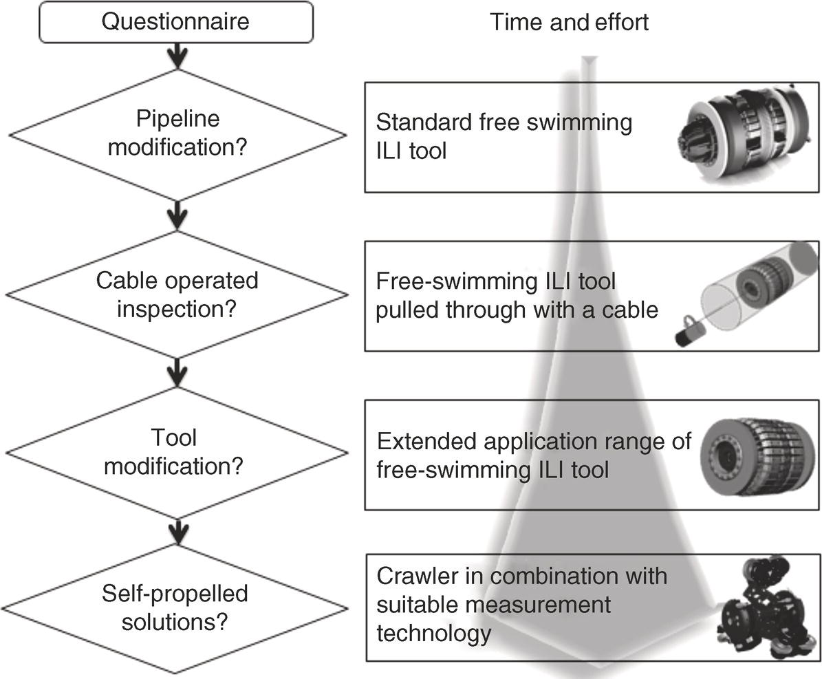
33.2.1 Pipeline Modification
33.2.2 Cable-Operated Inspection
33.2.3 Modification of Existing Tools
33.2.4 Self-Propelled Inspection
33.2.5 Selection Process
33.3 Free-Swimming ILI Tools For Challenging Pipeline Inspections
33.3.1 Bidirectional Inspection
33.3.2 ILI Tools for Launch Valve Operation
33.3.3 Low-Pressure Inspection of Gas Pipelines
33.3.4 Multidiameter Inspection
33.4 Self-Propelled Inspection Solutions
33.4.1 UT-Based Crawlers
33.4.2 MFL-Based Crawlers
33.4.3 Others
References
Bibliography: Sources of Additional Information
Journals, Conferences, and Other Sources with Content Related to Unpiggable Pipeline Inspections
Note