Abstract
Industrial combustion processes are unique compared to the other chapter subjects in this book by virtue of their scale and diversity. For example, a large flame produced by a flare in a petrochemical plant could exceed 100 m in length, and individual burners in large power boilers could be over 100 MW firing capacity each. There are numerous types of combustors that have many names such as heaters, furnaces, ovens, kilns, dryers, boilers, thermal oxidizers, crackers, reformers, and smelters. The processes range in temperatures from as low as 300K for some food heating and drying processes to as high as over 2,000 K for some glass and metals production processes. Fuels can be solid (e.g., coal), liquid (e.g., oil), or gaseous (e.g., natural gas). Some processes are batch (e.g., rotary aluminum melting furnaces) or continuous (e.g., float glass furnaces). The combustors come in a wide range of shapes and sizes including both horizontal (e.g., cement kiln) and vertical cylinders (e.g., vertical cylindrical process heaters), approximately spheres (e.g., electrical arc furnaces with supplement burners), and rectangular boxes (e.g., cabin heaters used in the petrochemical industry). Some include heat recuperation that may be recuperative (e.g., air preheaters used on process heaters) or regenerative (e.g., air preheaters used in glass melting furnaces). Some processes use oxygen-enhanced combustion ranging from low-level enrichment (e.g., to enhance scrap aluminum melting) up to complete replacement of the combustion air with pure oxygen (e.g., supplemental burners used to enhance electric arc furnaces).
Introduction
Industrial combustion processes are unique compared to the other chapter subjects in this book by virtue of their scale and diversity. For example, a large flame produced by a flare in a petrochemical plant could exceed 100 m in length, and individual burners in large power boilers could be over 100 MW firing capacity each. There are numerous types of combustors that have many names such as heaters, furnaces, ovens, kilns, dryers, boilers, thermal oxidizers, crackers, reformers, and smelters. The processes range in temperatures from as low as 300K for some food heating and drying processes to as high as over 2,000 K for some glass and metals production processes. Fuels can be solid (e.g., coal), liquid (e.g., oil), or gaseous (e.g., natural gas). Some processes are batch (e.g., rotary aluminum melting furnaces) or continuous (e.g., float glass furnaces). The combustors come in a wide range of shapes and sizes including both horizontal (e.g., cement kiln) and vertical cylinders (e.g., vertical cylindrical process heaters), approximately spheres (e.g., electrical arc furnaces with supplement burners), and rectangular boxes (e.g., cabin heaters used in the petrochemical industry). Some include heat recuperation that may be recuperative (e.g., air preheaters used on process heaters) or regenerative (e.g., air preheaters used in glass melting furnaces). Some processes use oxygen-enhanced combustion ranging from low-level enrichment (e.g., to enhance scrap aluminum melting) up to complete replacement of the combustion air with pure oxygen (e.g., supplemental burners used to enhance electric arc furnaces).
This chapter has been divided into six sections: metals industry, process heating, power generation, infrared heating and drying, flares, and oxygen-enhanced flames. Some of those sections are further broken down into subsections. The purpose of this chapter is not to attempt to be comprehensive, as that would be beyond the scope of the book, but rather to be representative of the many types of industrial combustion processes. This should give the interested reader a flavor for what combustion is used for in industry. As might be expected, heat transfer, thermal efficiency, pollution emissions, and reliability are important in most of these processes.
There are some good reference books on the subject of industrial combustion the interested reader could consult for further details on many of the processes pictured in this chapter. Griswold’s (1946) book is very practically oriented and includes chapters on gas burners, oil burners, stokers and pulverized-coal burners, heat transfer, furnace refractories, tube heaters, process furnaces, and kilns [1]. Stambuleanu’s (1976) book on industrial combustion has information on furnaces [2]. British Gas sponsored a very useful book on industrial combustion processes that specifically use natural gas as the fuel [3]. Trinks et al. (2004) have written what many consider to be the bible of industrial furnaces [4]. Deshmukh (2005) discusses a range of topics of interest in industrial combustion including fuels, burners, and refractories, where the emphasis is more on metal treatment [5]. Mullinger and Jenkins (2008) discuss a wide range of industrial furnaces and processes [6]. There is a series of books on industrial combustion that includes much information on a wide range of aspects including heat transfer [7], computational fluid dynamics [8], pollution [9], burners [10], testing [11], oxygen enhancement [12], and specific types of process in the petrochemical industry [13, 14].
5.1 Metals Industry
5.1.1 Ladle Preheating
Figure 5.1 shows a schematic of a burner firing into a vessel called a ladle that is used to transport molten metal from one station to another in a metals production plant. Burners are used to keep the refractory lining of the ladle hot so the molten metal will not freeze and solidify inside the ladle and the refractory will not be thermally shocked. Figure 5.2 shows a burner mounted in an end wall firing into a ladle. Figure 5.3 shows a burner firing on an end wall of a ladle preheating station without a ladle in place so the flames can be seen. This burner uses both air and oxygen as the oxidizer. The amount of oxygen used depends on the size of the ladle, the temperature of the ladle, the cost of the oxygen and the fuel, and the turnaround time needed for the ladle. Figure 5.3 shows a 2 MW natural gas flame firing with (a) minimum oxygen participation, (b) medium oxygen participation, and (c) maximum oxygen participation.
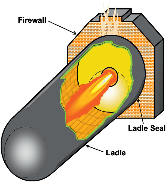
Figure 5.1 Drawing of a ladle used to transport molten metal which is being heated by a burner to keep the liquid metal from solidifying.
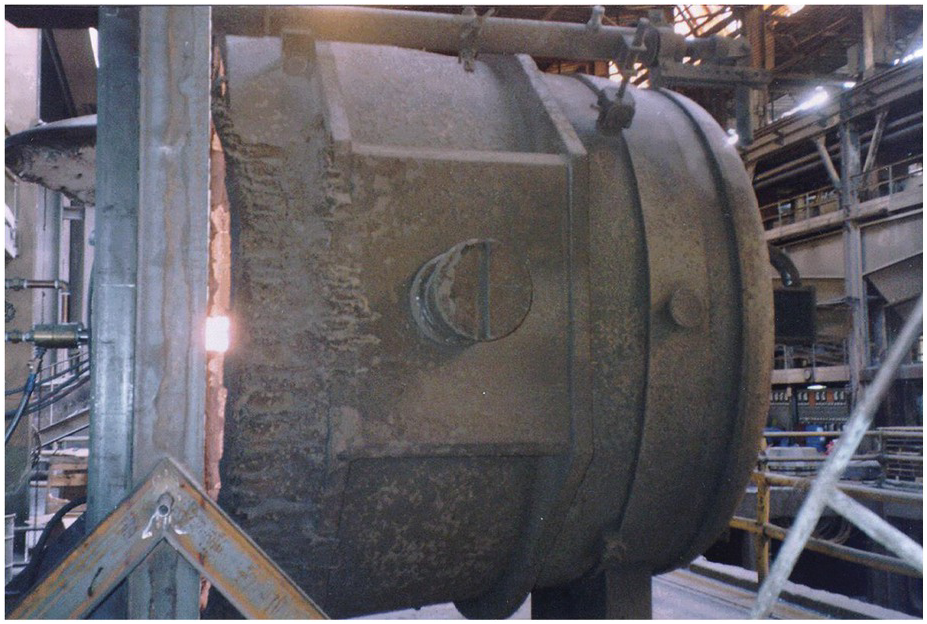
Figure 5.2 Actual ladle on a stand with a burner mounted on an endwall on the left with the burner firing from left to right.
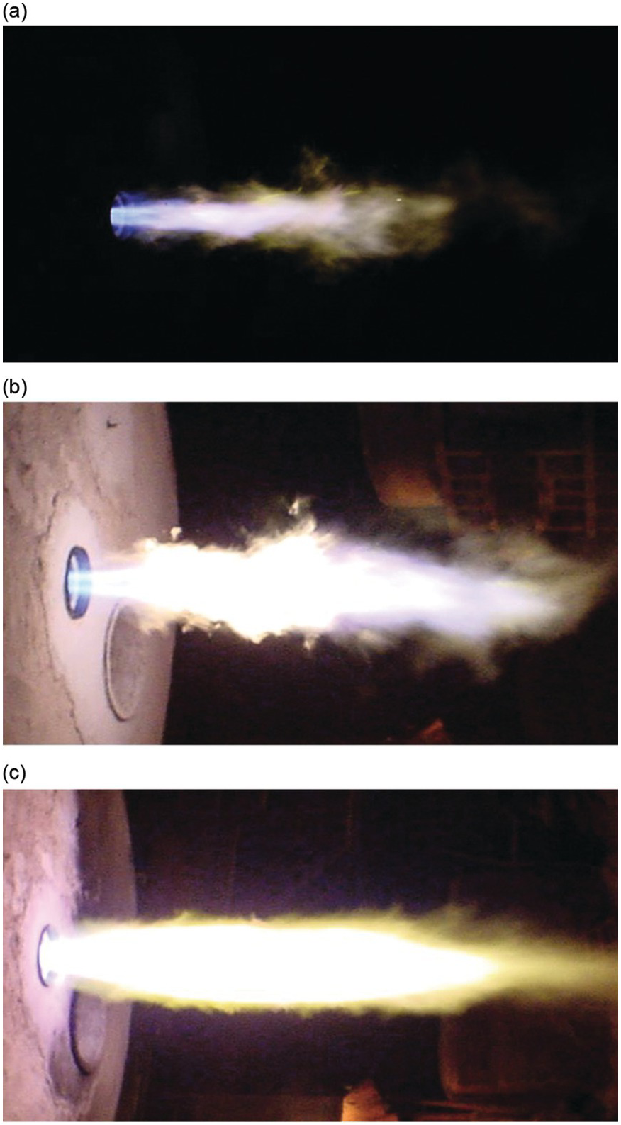
Figure 5.3 2 MW natural gas flame with (a) minimum oxygen enrichment of the combustion air, (b) medium oxygen enrichment, and (c) high-purity oxygen.
5.1.2 Experimental Investigation of a Concept of Low-Scale Reheating with Fuel-Rich Combustion
Industrial furnaces for reheating semifinished metal products are often direct fired with natural gas and air. To ensure a complete combustion, the furnaces are fired fuel lean. Oxidation of the metals exposed to the furnace atmosphere causes significant material losses and additional work in further processing. A reheating concept, which reduces scale formation, was developed. It involves fuel-rich combustion, post-combustion of the unburned off-gas, and efficient preheating of the combustion air. Experiments show a significant reduction of scale formation for copper and copper-nickel alloys in the off-gas of a fuel-rich combustion with an air ratio of λ = 0.96 and a maximum temperature of 950°C, but also for steel, alloy 1.2367 in off-gas of a combustion with an air ratio of λ = 0.95 and a maximum temperature of 1,152°C.
As part of the project, the primary combustion is investigated with different measurement techniques. To characterize the combustion at different operating conditions, especially the dimension of the flame, a camera system with an intensified CCD-sensor and a band pass filter (peak transmission at 308 nm) for the detection of OH*-chemiluminescence is used and compared to photos of the flame with an exposure time of 1/60 s. A conventional recuperative burner with a maximum capacity of 40 kW is used, which is fired with natural gas and cold air. The combustion chamber has a height of 0.94 m and a diameter of 0.6 m.
Figure 5.4 shows a photo of the flame compared to the measured OH*-intensity at a temperature of 900°C and 1,100°C, a burner capacity of 30.5 kW, and an air ratio of λ = 1.15. The figure of the OH*-intensity is obtained by calculating the average of 300 exposures that were recorded in 30 seconds. Figure 5.5 shows the distribution of the OH*-radicals for an increasing burner capacity from 10.4 kW to 40.5 kW at an air ratio of λ = 1.15 and a furnace temperature of 900°C. Figure 5.6 shows the distribution of the OH*-chemiluminescence at different air ratios at a furnace temperature of 1,050°C.
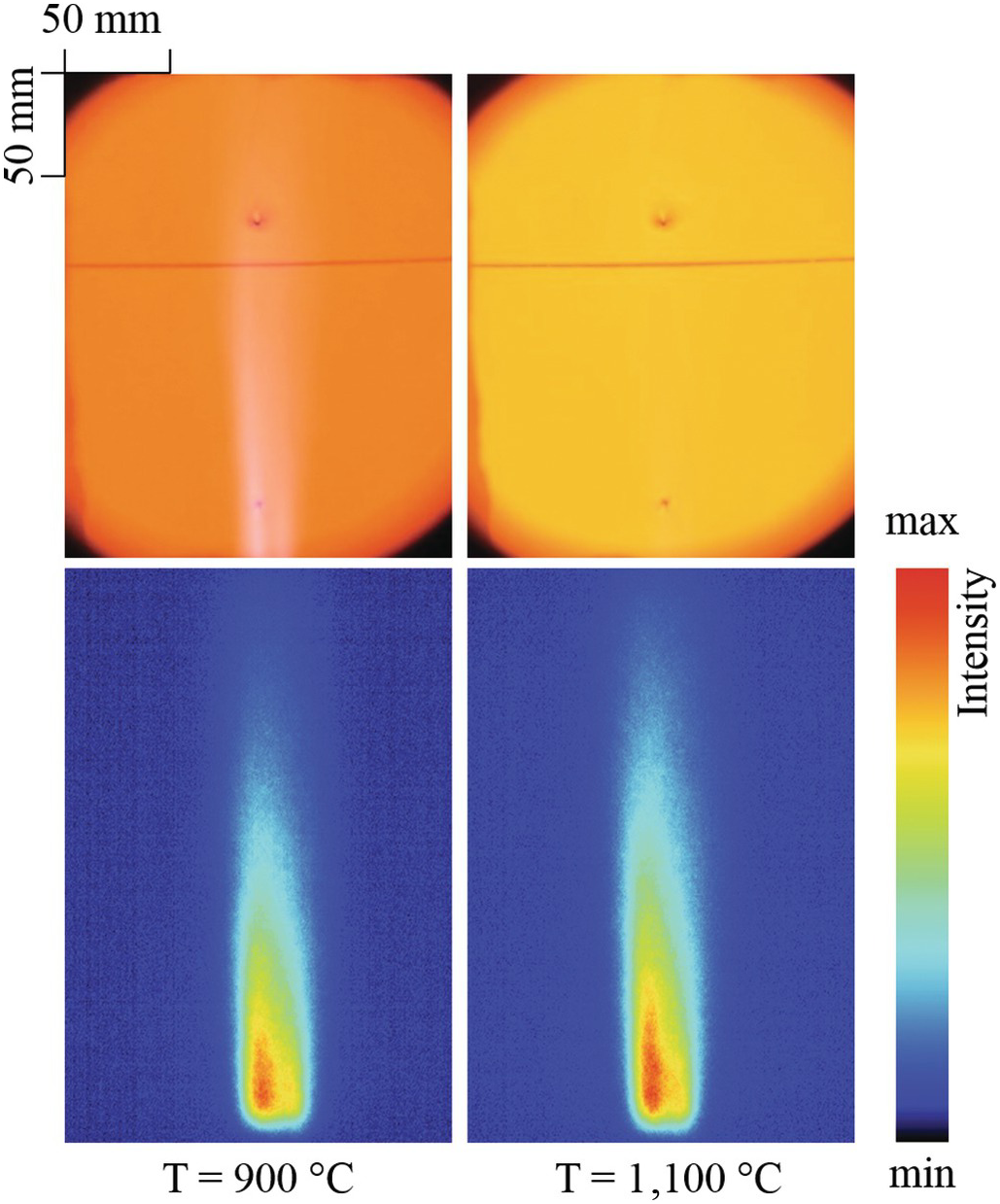
Figure 5.4 Photographs (top) and OH* intensity measurements for a recuperative burner used in metal reheating at furnace temperatures of 900°C and 1100°C.
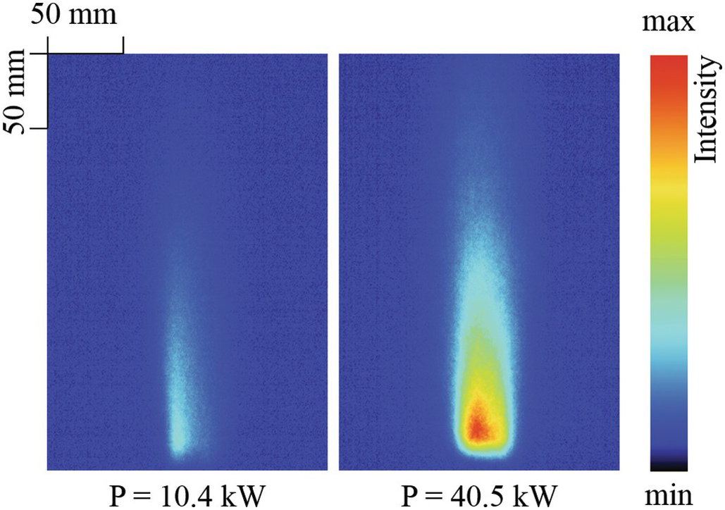
Figure 5.5 OH* intensity measurements for a recuperative burner used in metal reheating at 10.4 kW and 40.5 kW firing rates in a furnace at 900°C.
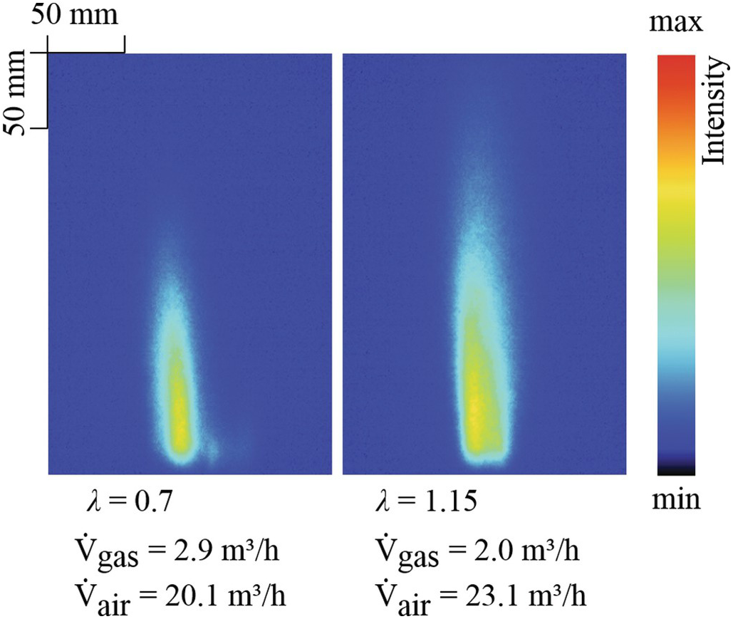
Figure 5.6 OH* measurements at different air/fuel ratios for a recuperative burner used in metal reheating in a furnace at 1050°C.
The results show a stable combustion for a burner capacity of 50–100% with an air ratio of 1.15–0.7, respectively. The burner capacity of 50% was limited due to soot formation. For the fuel-rich combustion the measurements of the OH*-distribution show a decreasing length of the reaction zone with increasing air ratio, whereas the position of the maximum intensity remains constant.
The project of the Research Association for the Mechanical Engineering Industry e. V. (FKM) proposed by the Research Association for Industrial Thermoprocessing Equipment e. V. (FOGI) was promoted via the German Federation of Industrial Research Associations e. V. (AiF, AiF-No. 17810 N) as part of the program for the promotion of Industrial Collective Research (IGF) by the Federal Ministry for Economic Affairs and Energy on the basis of a decision by the German Bundestag.
5.1.3 Flame Impingement
Direct flame impingement is used in the metals industry for reheating metals before they are shaped and formed. An example application is reheating the edge of a continuous metal sheet because the edges cool off more quickly than the center. The more nonuniform the temperature of the sheet, the more difficult it is to handle and process the metal, which often means either lower quality or more waste if the edges are cut off. Figure 5.7 shows a schematic of a flame impinging normal to a plane surface. A series of experiments were conducted using a commercial burner shown in Figure 5.8 made by Nordsea designed to using natural gas and high-purity oxygen. Figure 5.9 shows the effects of the oxidant composition with 5 kW natural gas flames using the following oxidants: (a) air and (b) high-purity oxygen. Figure 5.10 shows the effect of firing rate with oxygen/natural gas flames at firing rates of (a) 15 kW and (b) 35 kW. Figure 5.11 shows the effect of the distance between the burner and the target where (a) shows a close spacing and (b) shows a longer spacing.
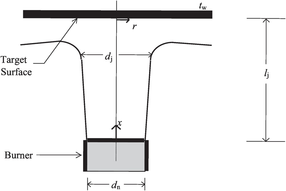
Figure 5.7 2D schematic of a flame jet impinging normally onto a plane surface.
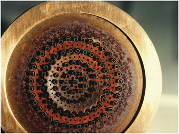
Figure 5.8 Outlet of a Nordsea burner designed to fire high-purity oxygen with natural gas for use in metal heating.
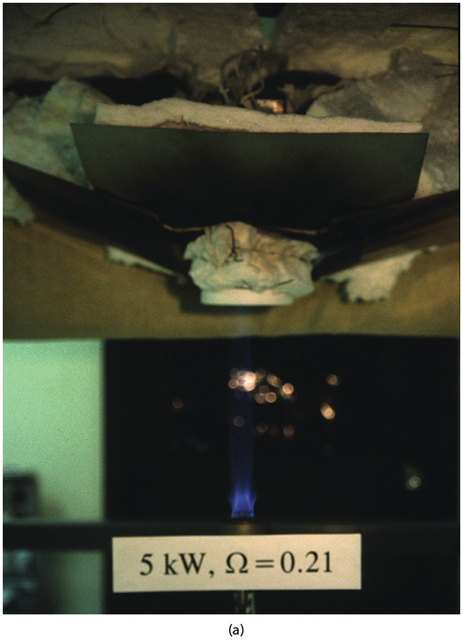
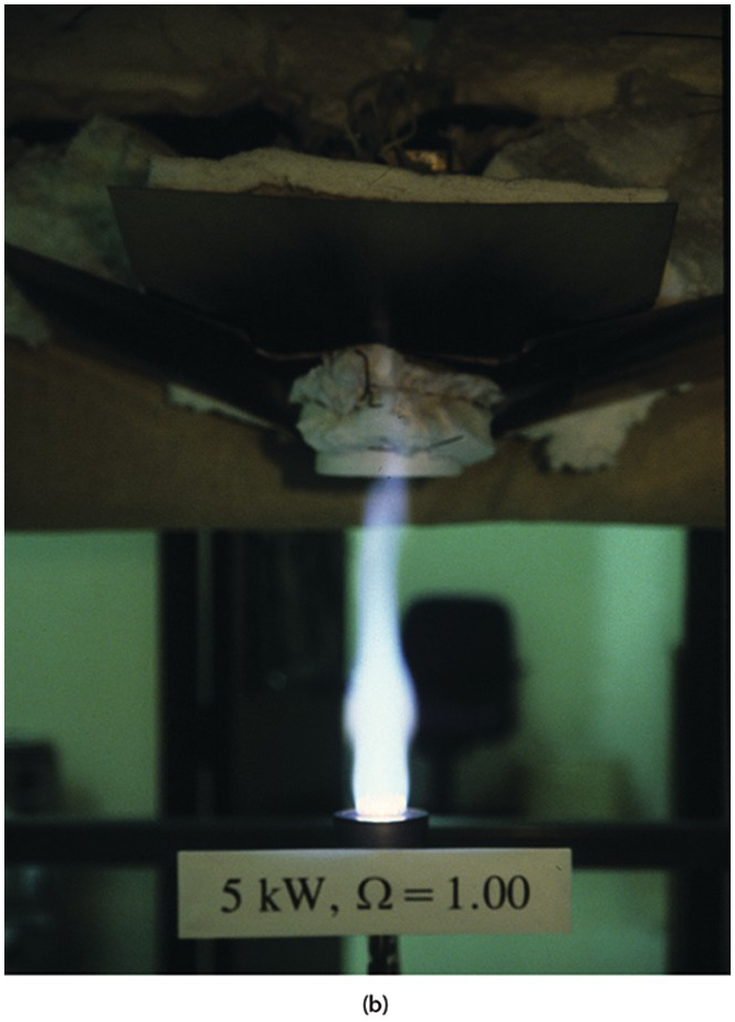
Figure 5.9 Burner in Figure 5.8 firing natural gas with (a) air and (b) high-purity oxygen.
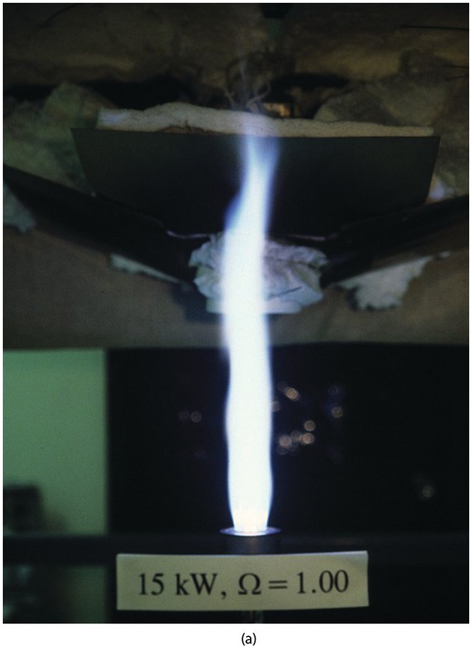
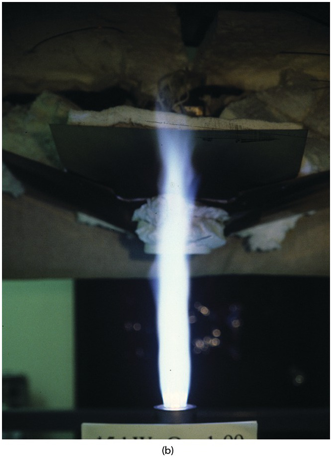
Figure 5.10 Burner in Figure 5.8 firing natural gas with high-purity oxygen at firing rates of (a) 15 kW and (b) 35 kW.
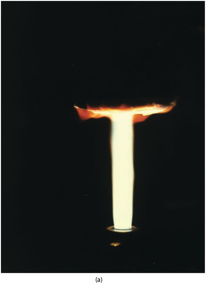
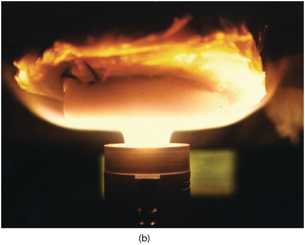
Figure 5.11 Burner in Figure 5.8 firing natural gas with high-purity oxygen with (a) long and (b) short spacing between the burner and the plane target surface.
This research was partially funded by the Gas Research Institute (Chicago, IL) for the project entitled “Development of Rapid-Heating Furnaces for Metal Reheating.”
5.1.4 Development of an Energy-Efficient Burner for Heat Treatment Furnaces with a Reducing Gas Atmosphere
A main reason for metal loss of semifinished metal products during heating in reheating and heat treatment furnaces is scale formation. In this project, a burner was developed that produces a low oxidizing (reducing) atmosphere in the furnace. A recuperative burner generates a reducing furnace atmosphere due to fuel-rich combustion of natural gas and air. Complete combustion of the furnace atmosphere is ensured by injection of additional air and takes places in an open radiant tube resulting in high process energy efficiency.
Experimental and numerical methods were used to quantify operating conditions for the prototype burner design. The experimental setup consisted of a concept-burner (see Figure 5.12), which is installed in a combustion chamber. In the experiments, off-gas composition and temperature in the annular gap and in the off-gas after the recuperator were measured to determine the maximum temperature in the annular gap, length of the post-combustion zone, off-gas emissions, and energy efficiency of the burner.
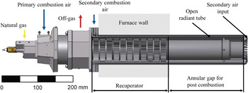
Figure 5.12 Drawing of a concept burner installed in a heat treating furnace.
The burner operates in a flame and a flameless combustion mode. Figure 5.13 shows the burner in the flameless combustion mode, which is fired with natural gas and air. The secondary air for the post-combustion of the off-gas is injected through small metallic tubes at the off-gas inlet of the open radiant tube. The burner is designed for a maximum capacity of 40 kW. The primary, fuel-rich combustion was investigated for different air–fuel ratios in the range of 0.7 ≤ λprimary < 1. The total air ratio is less λtotal < 1.05.
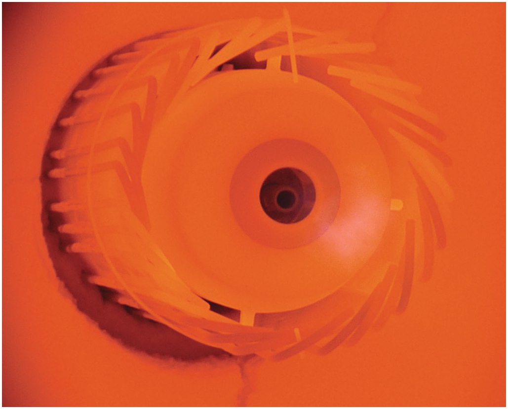
Figure 5.13 Burner shown in Figure 5.12 operating in flameless mode.
Figure 5.14 shows the burner firing in the flame mode. Secondary air is injected inside the annular gap. Therefore, there is no need for metallic tubes outside of the open radiant tube. The nominal burner capacity was 80 kW. The burner operated with a primary air ratio of λprimary = 0.75 and a total air ratio of λtotal ≈ 1.15, depending on the fuel and oxidizer. Due to the combination of fuel-rich combustion and post-combustion, the total NOX emissions were low. For further reduction and temperature homogenization, the burner can operate in the flameless combustion mode (see Figure 5.15).
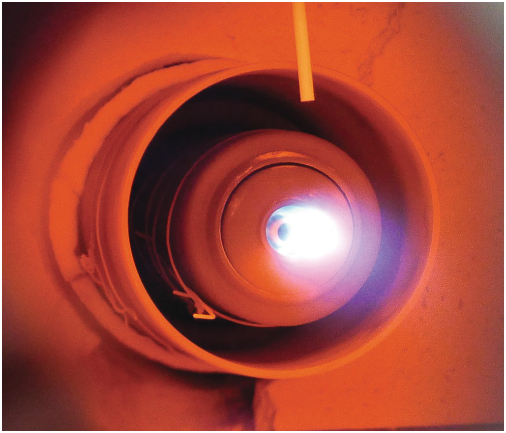
Figure 5.14 Burner shown in Figure 5.12 operating in the visible flame mode with secondary air injection.
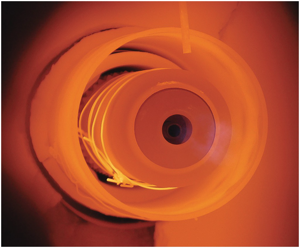
Figure 5.15 Burner shown in Figure 5.14 operating in the flameless mode.
This project is supported in the Central Innovation Programme for SMEs (ZIM) by the Federal Ministry for Economic Affairs and Energy on the basis of a decision by the German Bundestag.
5.1.5 Experimental Investigation of the Combustion in Small Radiant Tubes for Multi-chamber Furnaces
The aim of this research-and-development project was an increase in efficiency and profitability of multi-chamber furnaces for press hardening. Therefore, an innovative furnace concept was developed, which is heated with small gas-fired radiant tubes. The concept consists of a modified multi-chamber furnace, which increases flexibility and productivity and reduces resource and energy consumption. Due to a compact design of furnace and heating components, less floor space is needed. Key components are small radiant tubes, which are fired with natural gas and air. These radiant tubes are used instead of conventional electric heating units.
Experimental investigations were done in a test combustion chamber with small radiant tubes made of glass. The internal dimensions of the combustion chamber were 480 mm × 300 mm × 1,630 mm (width × height × depth), with an insulation of 200 mm. The radiant tubes had a maximum diameter of 80 mm and a length of approximately 2,200 mm. The radiant tubes were heated with natural gas and cold air, which were fed into the radiant tube through a test burner. Different test burners were investigated. The focus of the investigation was on the stability of the combustion, the off-gas emissions, and the temperature profile at the surface of the radiant tube. Therefore, off-analysis and thermocouples are used.
Figure 5.16 shows a photo of the combustion in the radiant tube with a burner capacity of 7.5 kW and an air ratio of λ = 1.05. In further investigations, the burner capacity was increased up to 15 kW. The air ratio was < 1.09. Due to a gradient in temperature over the length of the radiant tube, the burner configuration was modified with numerical methods.

Figure 5.16 Radiant tube burner used in metal heating firing at 7.5 kW.
Figure 5.17 shows a photo of the combustion in the radiant tube with a modified test burner, based on numerical simulations, with a burner capacity of 10 kW and an air ratio of 1.08. In further investigations, the burner capacity was increased up to 15 kW. The air ratio was < 1.08. For more reduction of the CO emissions, the air ratio was increased to 1.25. The results showed changing combustion characteristics, but the temperature gradient was still in the same range.

Figure 5.17 Modified radiant tube burner firing at 10 kW.
To improve temperature distribution in the furnace, two radiant tubes were installed in the combustion chamber, with burners firing in opposite directions (Figure 5.18). The burners in this case were fired with a capacity of 15 kW each and an air ratio of 1.09. In -this test configuration, the temperature gradient was reduced from approximately 70 K to approximately 30 K.

Figure 5.18 2 burners shown in Figure 5.17 firing in opposite directions inside a combustion chamber.
This project was supported in the Central Innovation Programme for SMEs (ZIM) by the Federal Ministry for Economic Affairs and Energy on the basis of a decision by the German Bundestag.
5.1.6 Experimental and Numerical Investigation to Improve the Lifetime of Metallic Recirculating Radiant Tubes
Radiant tubes operate at a high thermal and mechanical load. A premature failure of the tubes reduces the heat input to the furnace and therefore reduces productivity. The worst case would be the stop of the furnace. Besides choosing the appropriate material and a good dimensioning of the burner–radiant tube system, different influences lower the lifetime of radiant tubes.
In this project, some aspects of tube design were investigated using modern computational methods. These tools are very valuable to gain a better understanding of the complex mechanisms that can lead to premature tube failures. However, so far it is not possible to make exact predictions of tube life. There are still many phenomena, especially regarding high temperature creeping, which cannot be completely described. The other difficulty is that the boundary conditions of real operating data are largely unknown. However, despite its limitations, it can be very fruitful for suppliers and operators to cooperate with researchers to get a better understanding of their processes.
Figure 5.19 shows the experimental setup. For the experimental investigations and validation of the numerical models, a p-type test radiant tube was used, which was installed in an air-cooled combustion chamber. The radiant tube was fired with a recuperative burner fed with natural gas and air with a capacity of 120 kW and an air ratio of approx. λ = 1.05. The radiant tube was equipped with an observation window to characterize the combustion.

Figure 5.19 Experimental setup for a test of recuperative recirculating radiant tube burners used in metal heating applications.
Figure 5.20 shows the outlet of the burner. The burner operates in the flame mode. There is a visible blue flame at the outlet of the combustion chamber of the burner. To minimize NOX, emissions the burner can operate in a flameless combustion mode.
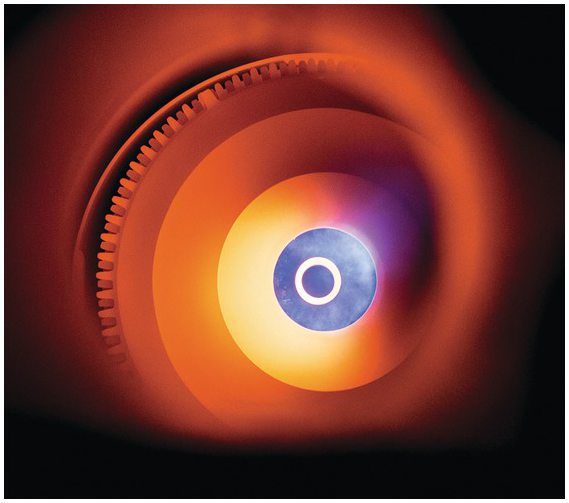
Figure 5.20 Outlet of a recuperative recirculating burner operating in the visible flame mode.
Figure 5.21 shows the outlet of the burner operating in the flameless combustion mode. In this case, there is no visible flame at the outlet of the burner; instead, the combustion reactions take place in a large reaction zone.
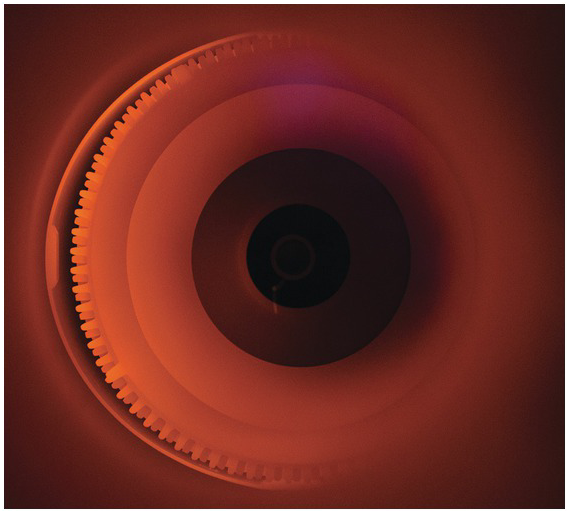
Figure 5.21 Outlet of a recuperative recirculating burner operating in the flameless mode.
The project of the Research Association for the Mechanical Engineering Industry e. V. (FKM) proposed by the Research Association for Industrial Thermoprocessing Equipment e. V. (FOGI) was promoted via the German Federation of Industrial Research Associations e. V. (AiF, AiF-No. 17840 N) as part of the program for the promotion of Industrial Collective Research (IGF) by the Federal Ministry for Economic Affairs and Energy on the basis of a decision by the German Bundestag.
5.2 Process Heating
5.2.1 Typical Burners
5.2.1.1 Typical Process Burner Flame Shapes
In the process heating industry, by far the two most common flame shapes are round and rectangular. Figure 5.22a shows a drawing of a COOLstar® burner designed to produce a round flame shown in Figure 5.22b. Figure 5.23 shows a John Zink Hamworthy Combustion LPMF burner designed to produce a rectangular, sometimes referred to as a flat, shape flame as seen in Figure 5.23b.
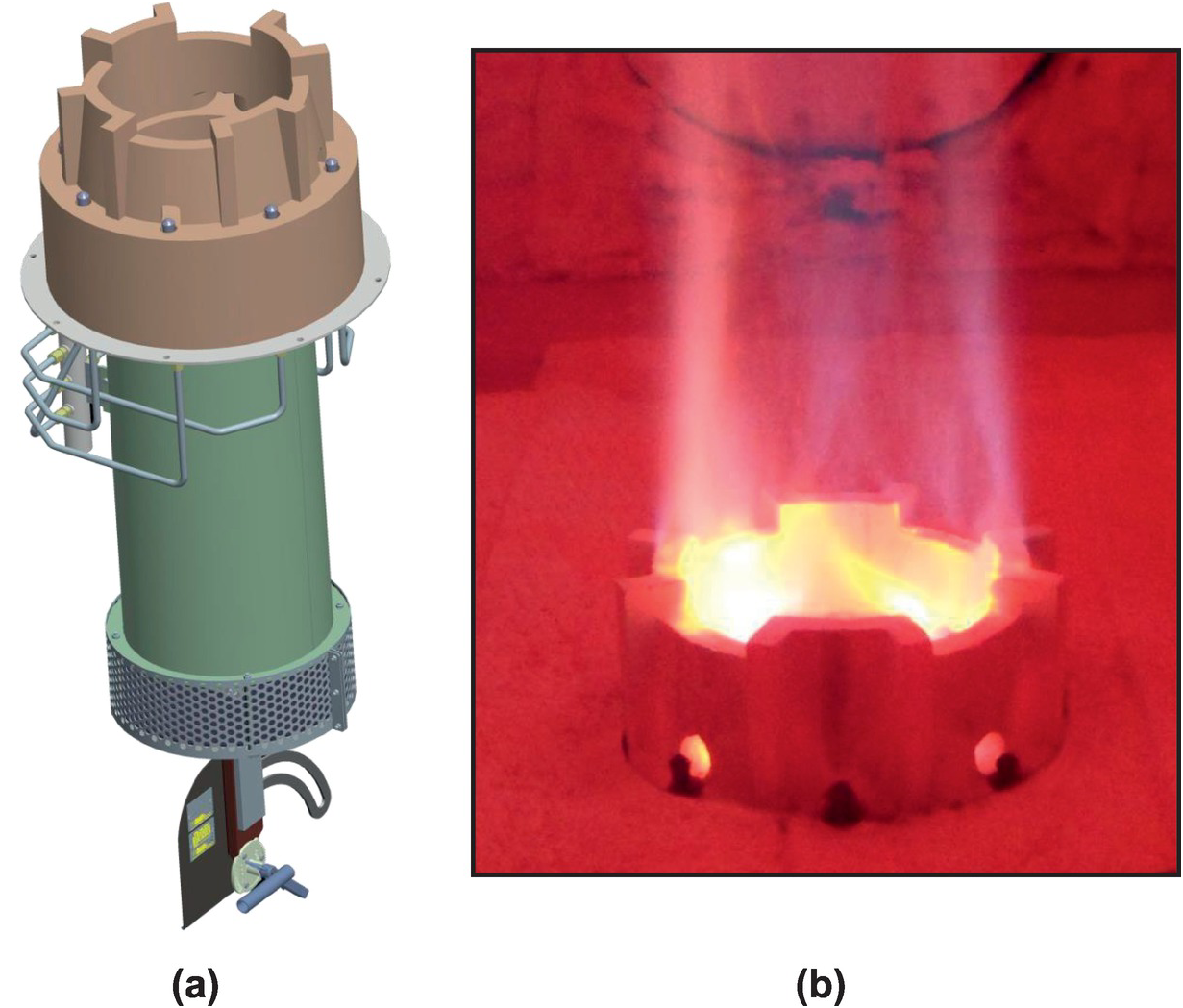
Figure 5.22 John Zink Hamworthy Combustion COOLstar® burner designed for ultra-low-NOx with a round flame shape.
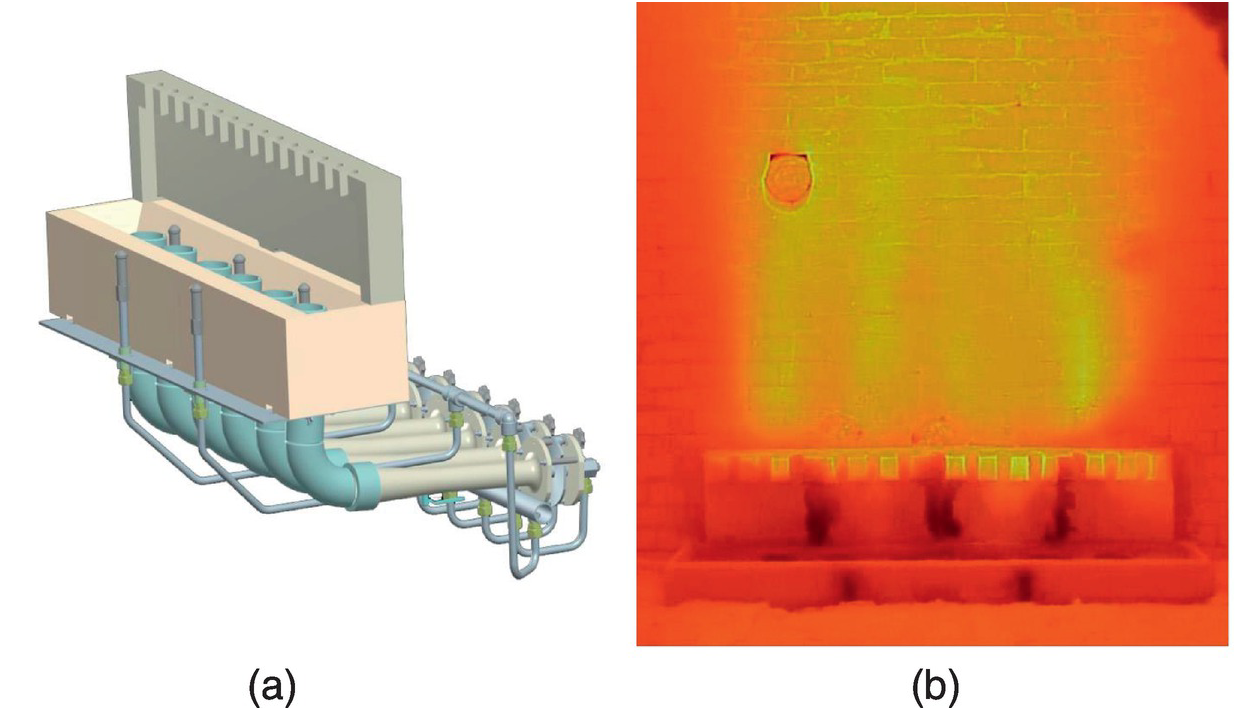
Figure 5.23 John Zink Hamworthy Combustion LPMF burner designed for ultra-low-NOx with a rectangular (“flat”) flame shape.
5.2.1.2 Freestanding Burners
Freestanding burners are located away from the walls and generally fire upwardly. Two of the most common examples are shown here. Figure 5.24 shows a sketch and a photo of a cabin heater where burners are aligned in one or more straight rows. Figure 5.25 shows flames in a crude unit where the burners are firing on refinery fuel gas. Figure 5.26 shows a drawing and photo of a vertical cylindrical (VC) heater. Figure 5.27 shows flames from four burners in a circle firing refinery fuel gas in a VC heater.
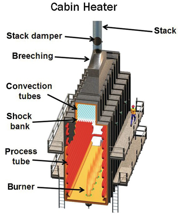
Figure 5.24a Cabin-style fired heater: (a) drawing.
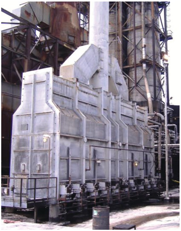
Figure 5.24b Cabin-style fired heater: (b) photograph.
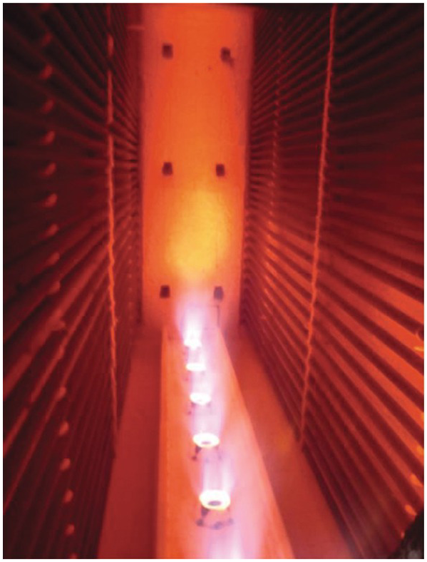
Figure 5.25 Row of round burners firing in a cabin-style fired heater.
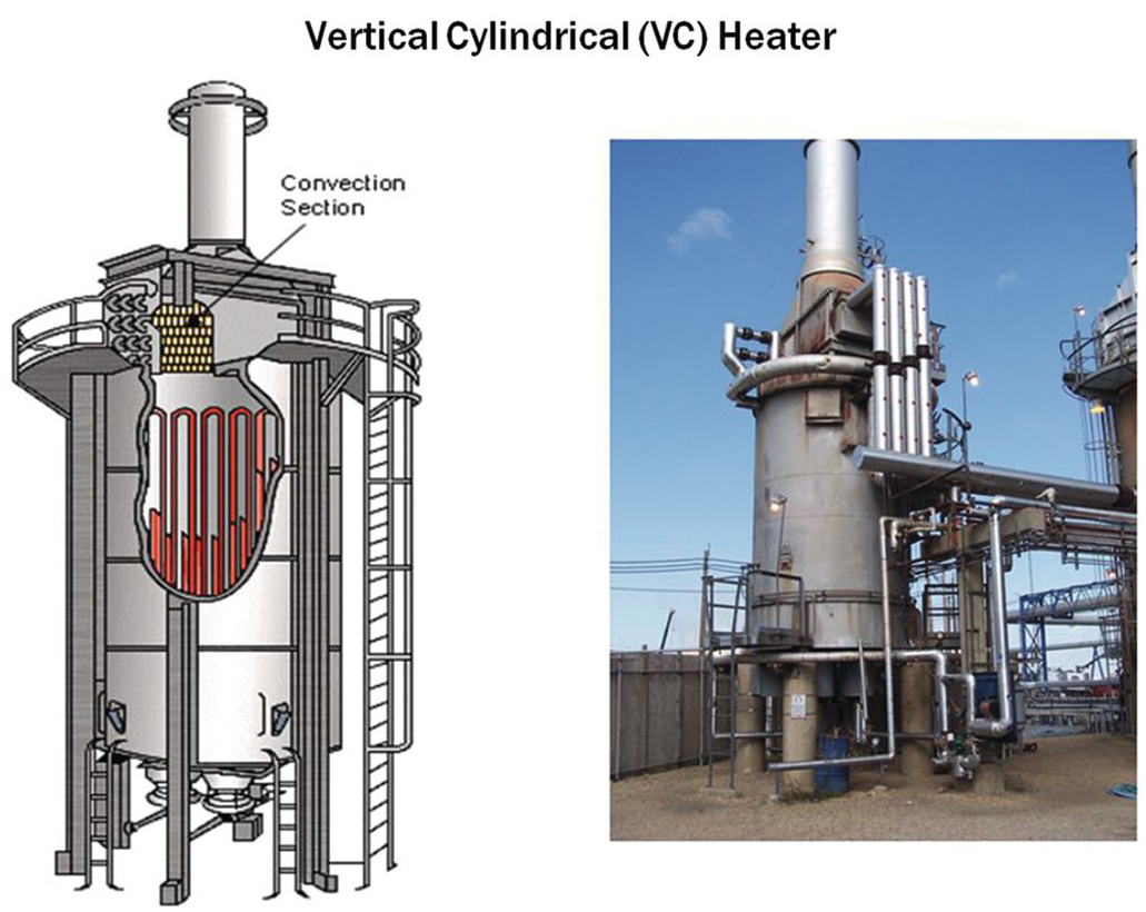
Figure 5.26 Vertical cylindrical fired heater.
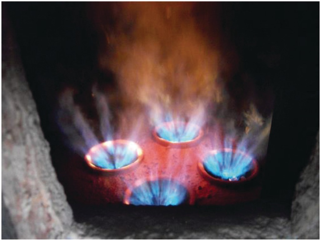
Figure 5.27 4 round burners firing in a vertical cylindrical heater.
5.2.1.3 Wall-Fired Burners
Wall-fired burners are designed to fire along a wall so the wall can radiate heat to process tubes located fairly close to the burners. The burner outlet is commonly rectangular with a high length-to-width ratio to get as much flame coverage along the wall as possible. These burners are commonly called flat flame burners because of the shape. Figure 5.28 shows a conventional wall-fired burner commonly used in the floor of ethylene cracking furnaces. Figure 5.29 shows an ultra-low-NOx version of this type of burner. Figure 5.30 shows flat flame burners firing up a wall on the left to heat process tubes on the right.
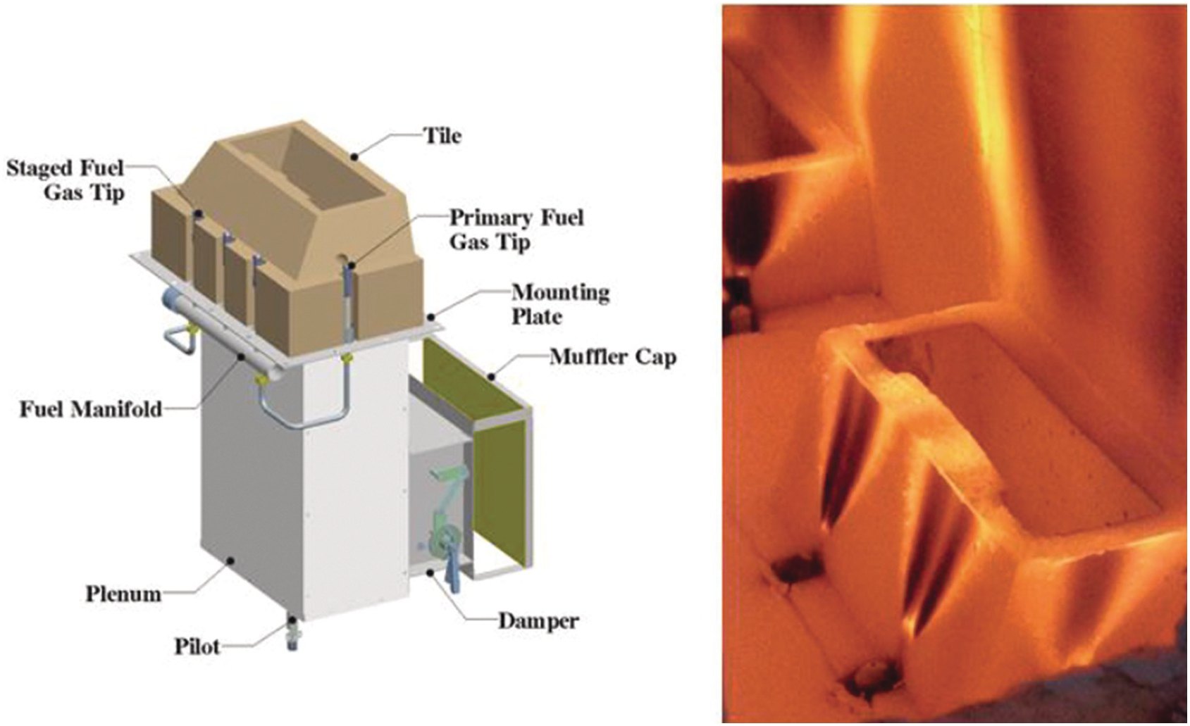
Figure 5.28 Conventional wall-fired burner.

Figure 5.29 Ultra-low-NOx wall-fired burner.
Figure 5.30 Rectangular (“flat”) flame burners firing vertically upward along a wall in a fired heater.
5.2.1.4 Radiant Wall Burners
Figure 5.31 is a cutaway view of a natural draft radiant wall burner commonly used in ethylene cracking furnaces with a typical capacity of approximately 0.3 MW. Figures 5.32a and 5.32b show side and front views, respectively, of this burner firing in a test furnace. Figure 5.33 shows an array of these burners firing in an ethylene cracking furnace at approximately 1,200°C. Figure 5.34 shows a forced draft radiant wall burner: (a) assembly drawing; (b) burners firing in an ethylene furnace.
Figure 5.31 Natural draft radiant wall burner assembly.
Figure 5.32a Natural draft radiant wall burner flame (side view).
Figure 5.32b Natural draft radiant wall burner flame (front view).
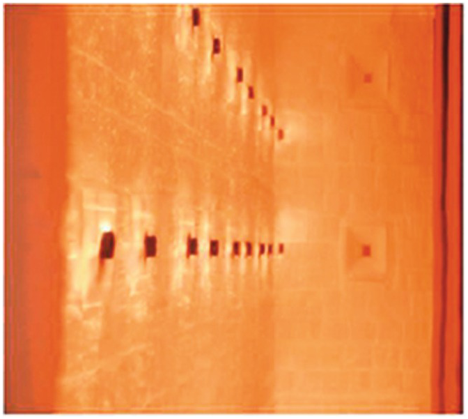
Figure 5.33 Natural draft radiant wall burners in an ethylene furnace.
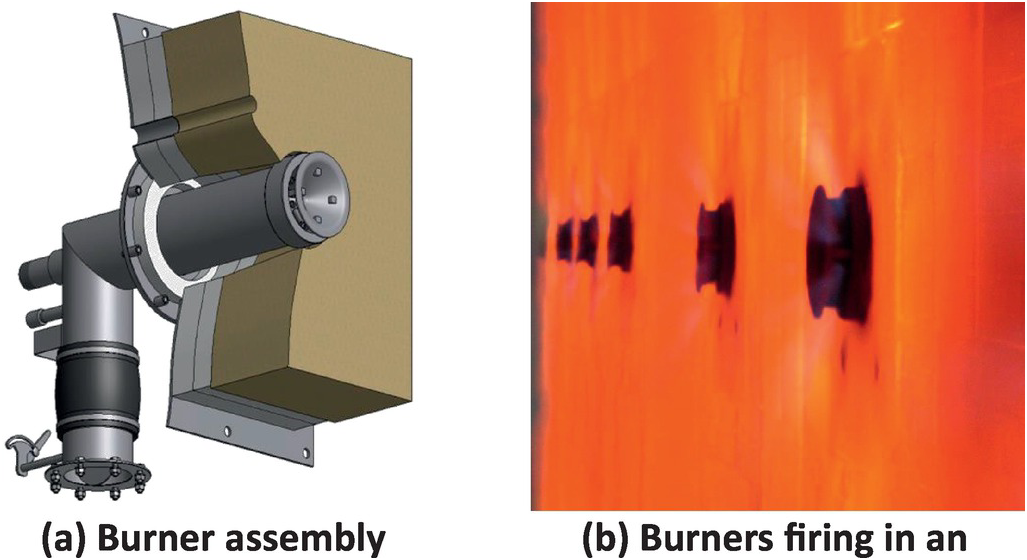
Figure 5.34 Forced draft radiant wall burner.
5.2.1.5 Downfired Burners
Downfired burners are mounted in the roof of the furnace and fired downward as shown in Figures 5.35 and 5.36. They are commonly used in reforming furnaces used to produce hydrogen (H2) and ammonia (NH3). Figures 5.37a and 5.37b show a drawing of a typical burner and a closer view of a single burner firing, respectively. These burners often fire on two separate fuels simultaneously where the primary fuel is typically natural gas and the secondary fuel is an off-gas generated from the production of hydrogen. That secondary fuel gas typically has high concentrations of carbon monoxide (CO) and hydrogen (H2) and is at a low pressure. Figure 5.38 shows a downfired burner firing on naphtha, which is a common liquid fuel used in this application.
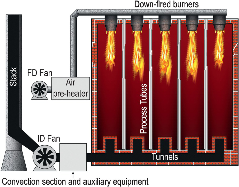
Figure 5.35 Downfired reformer schematic.
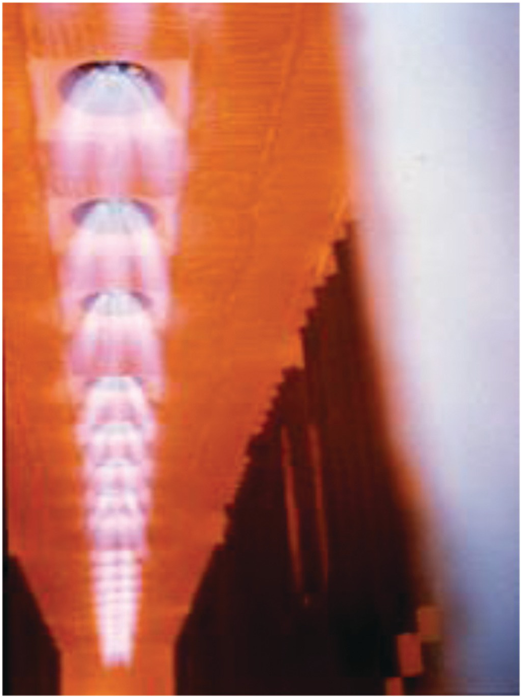
Figure 5.36 Downfired burners firing in a reformer.

Figure 5.37 Example of a downfired burner.
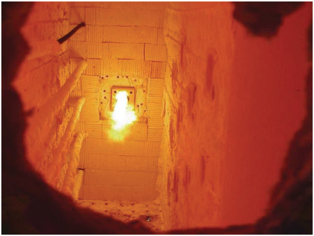
Figure 5.38 Example of a downfired burner firing on naphta.
5.2.2 Burner Operations
5.2.2.1 Gaseous Fuel Effects
The fuel composition has a large impact on the flame characteristics such as length, width, color, and intensity when the burner fuel nozzles have fixed openings. Figure 5.39 shows the effect of the fuel composition for a fixed firing rate where the fuel pressure is varied to maintain the firing rate. Figure 5.40 shows the same fuels used in Figure 5.39 where the fuel pressure remained constant while the firing rate and excess O2 varied. Figure 5.41 shows three different fuels firing through the same burner at a constant firing rate. This shows the dramatic impact of fuel gas composition for fixed fuel orifices.
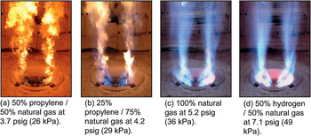
Figure 5.39 Changing fuel composition while maintaining a constant heat release of 3.2 × 10⁶ Btu/hr (0.94 MW), furnace temperature of 1,375°F (746°C), and excess O2 of 3% dv.
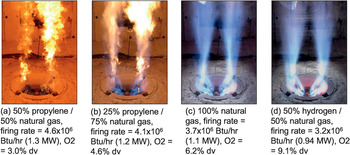
Figure 5.40 Changing fuel composition while maintaining a constant fuel pressure of 7 psig (48 kPa).
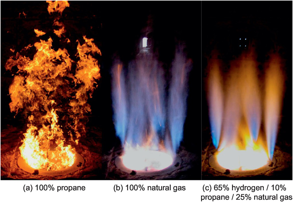
Figure 5.41 Flame shapes for different fuel compositions at a constant firing rate of 2.5 × 10⁶ Btu/hr (0.73 MW).
5.2.2.2 Oil Firing
Liquid fuels are more challenging to fire because of the need to atomize the liquid into very fine droplets to get proper combustion. Figure 5.42 shows a drawing of a typical dual fuel burner capable of firing a gaseous or liquid fuel. Figure 5.43 shows the fine atomization required for proper combustion. Figure 5.44 is a burner firing heavy (no. 6) oil. Figure 5.45 shows a comparison of the same burner at approximately the same firing rate and furnace temperature firing on (a) oil and (b) refinery fuel gas. The oil flame is much more luminous than the gas flame.
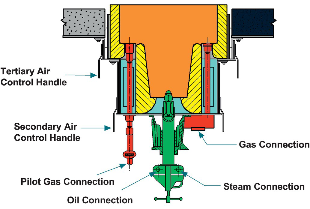
Figure 5.42 Combination burner cross-sectional drawing
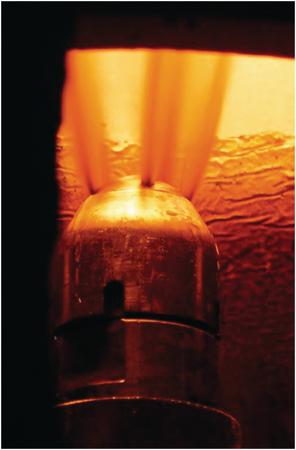
Figure 5.43 Oil atomization.
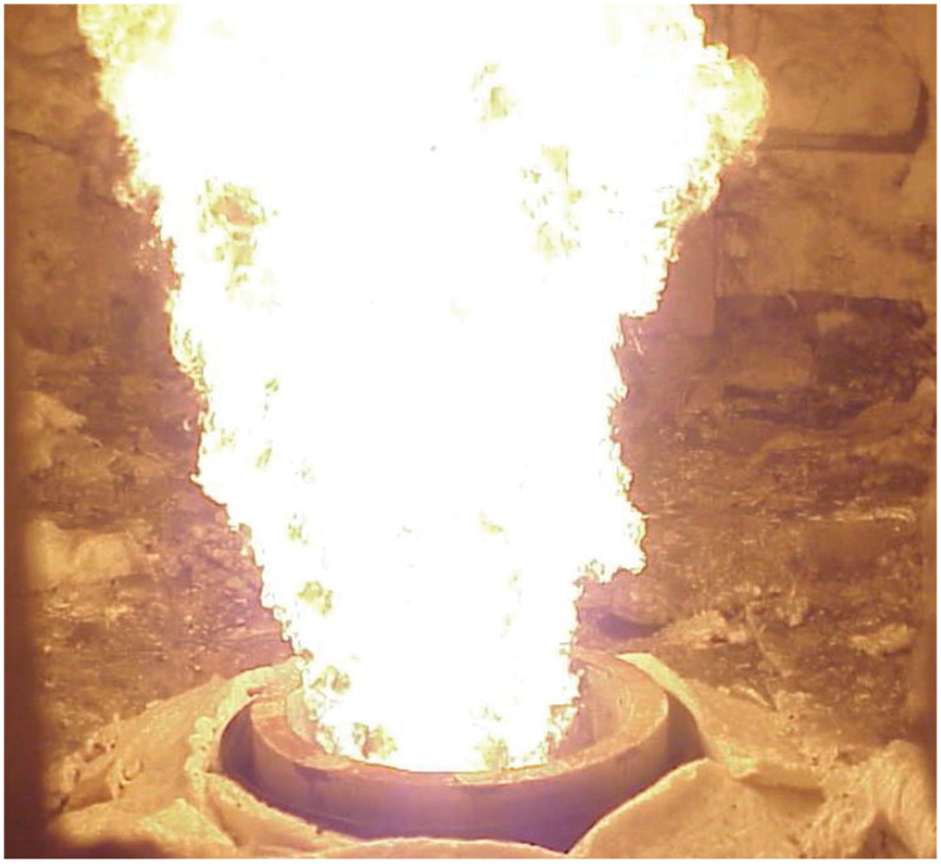
Figure 5.44 Burner firing no. 6 oil.
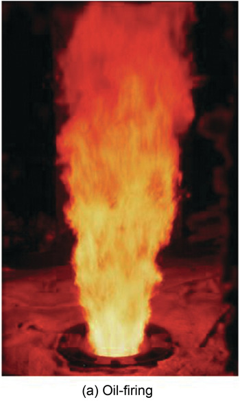
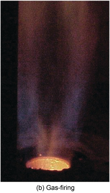
Figure 5.45 Combination burner firing on (a) oil and (b) gas.
5.2.2.3 Burner Spacing
The spacing between burners is critical to performance in multi-burner systems. Figure 5.46 shows what happens when the spacing between birthday candles changes. Individual flames coalesce into one large flame when the spacing is too close. Figure 5.47 shows an actual example in a vertical cylindrical furnace where the burners are in a circle but too closely spaced, which does not allow for flue gas flow between the burners into the center. This creates a low-pressure region that actually caused erosion of the refractory floor. Figure 5.48 shows the effect of linear burner spacing on flame length and interaction. Burners are normally designed to have minimal interaction with adjacent burners. Excessive flame interaction can produce much larger flames than desired.
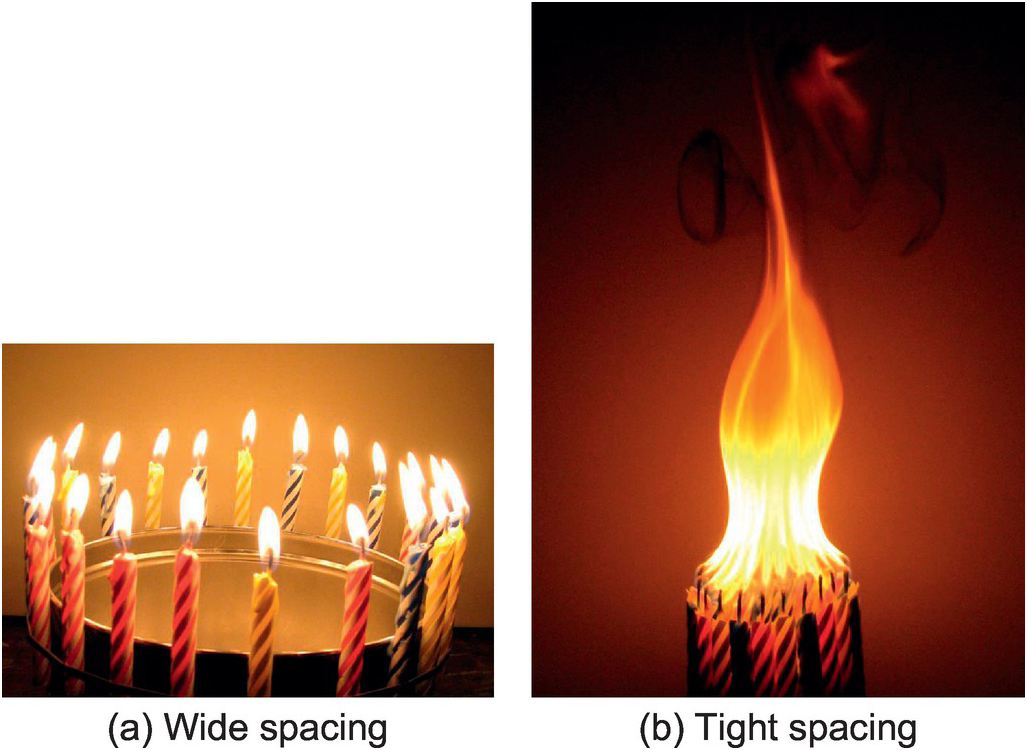
Figure 5.46 Birthday candles in a circle.
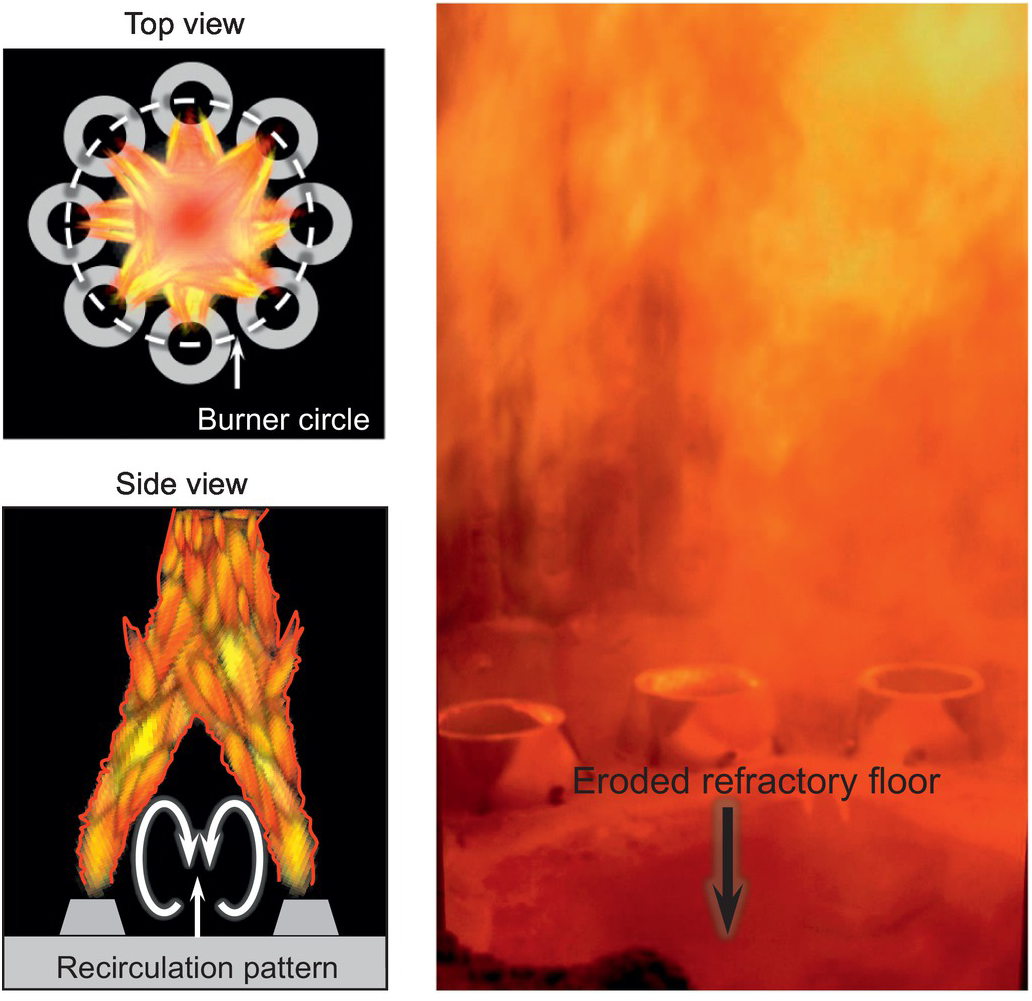
Figure 5.47 Vertical cylindrical furnace with burners too closely spaced in a circle.
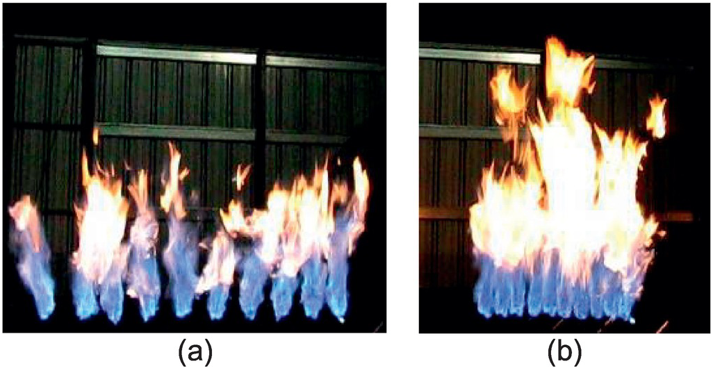
Figure 5.48 Diffusion burners arranged in a straight line: (a) burners spaced so no flame interaction and (b) burners at half the spacing shown in (a).
5.2.2.4 Examples of Burner Problems
There are numerous possible burner problems, so only a few examples are given here. Figure 5.49 shows two wall-mounted burners where some of the fuel injectors on the bottom burner are plugged (no flames in parts of the lower half). Figure 5.50a shows a burner with some plugged fuel injectors before cleaning. Figure 5.50b shows the same burner after the injectors have been cleaned. Figure 5.51 shows a flame flashing back inside a single radiant wall burner. The likely cause is some type of pluggage. Note the other burners near it are not flashing back.
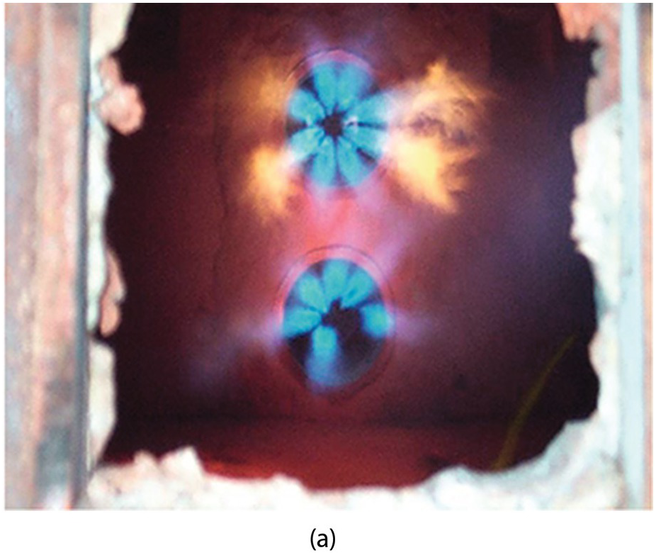
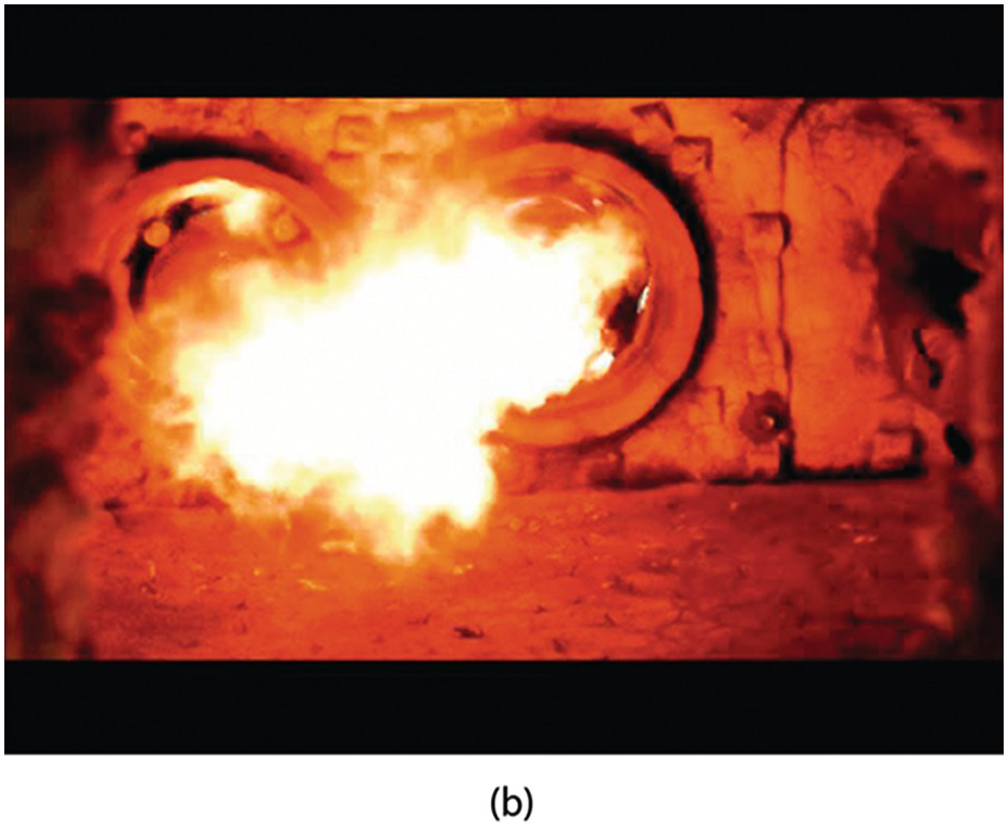
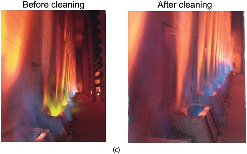
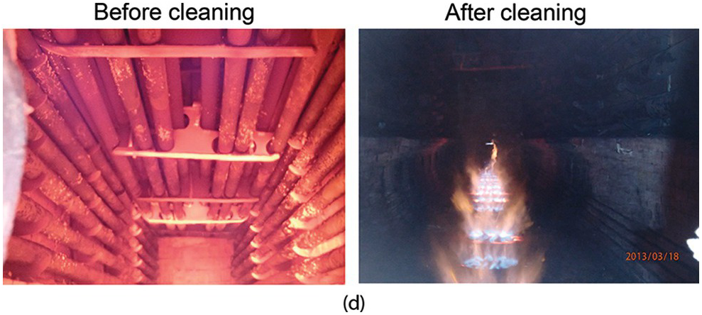
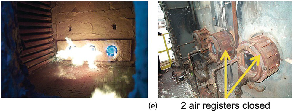
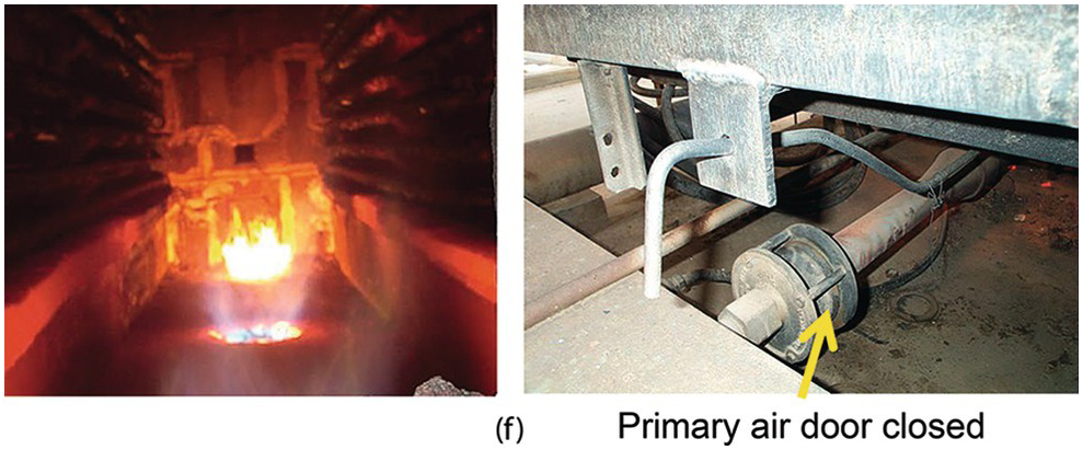
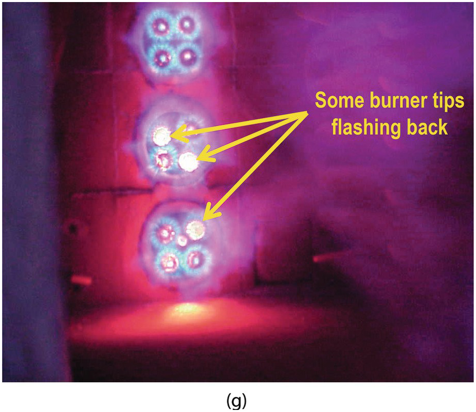
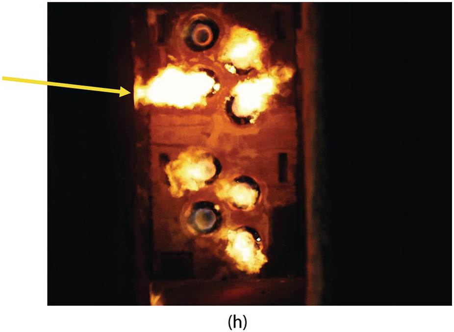
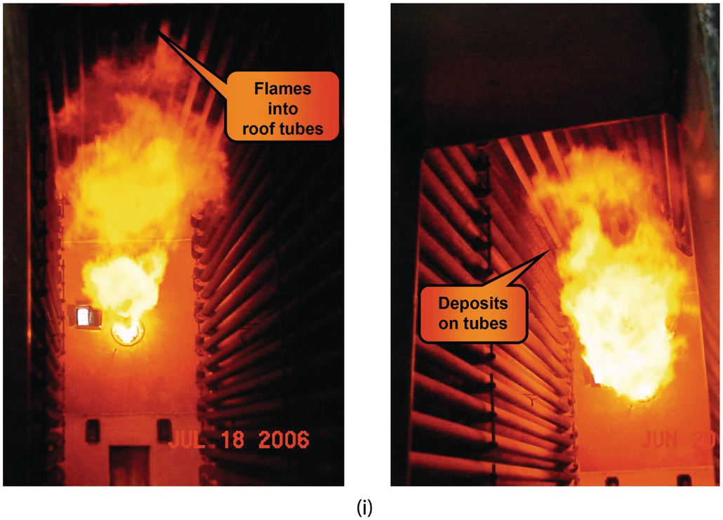
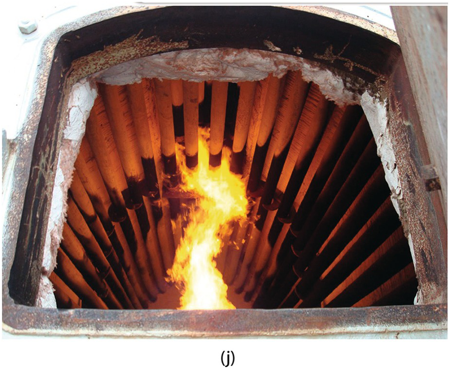
Figure 5.49 Irregular flames: (a) lower burner fuel injectors partially or totally plugged forcing more fuel to the upper burner causing yellow tails on some of the flames due to lack of air, (b) flames impinging on each other, (c) burners firing up a wall in an ethylene furnace before and after cleaning, (d) cabin heater before and after the burners were cleaned, (e) flames with 2 air registers closed, (f) rear flame with primary air door closed, (g) some burner tips flashing back, (h) flame impingement against the left side wall, and (i) and (j) flame impingement against the convection section tubes in a cabin heater.
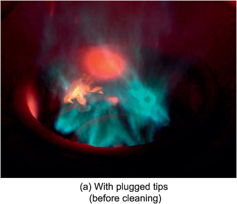
Figure 5.50a Floor-fired burner with (a) plugged tips (fuel injectors) and without plugged tips.

Figure 5.50b Floor-fired burner after plugged tips (fuel injectors) have been cleaned.
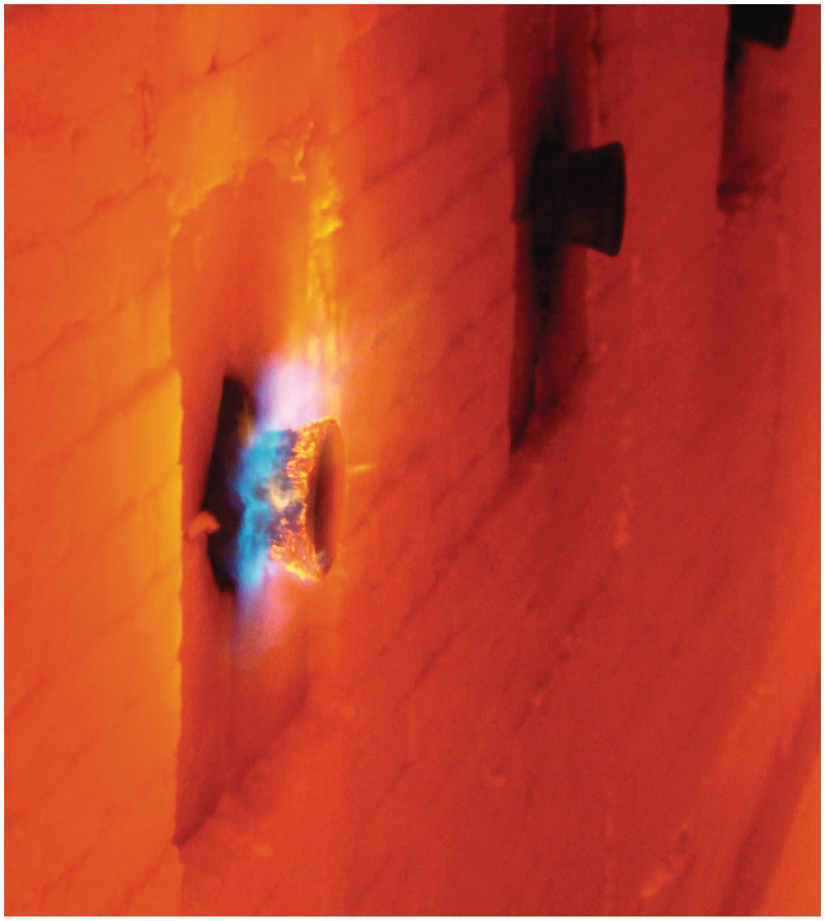
Figure 5.51 Flame flashing back inside a radiant wall burner.
5.2.2.5 Adjusting Burners
These photos show the improper operating conditions before adjusting the burners and the proper operating conditions after adjusting the burners. Figure 5.52 shows flat flame burners firing horizontally across the floor of a cabin heater before and after adjusting the draft and excess O2. Figure 5.53 shows round burners firing vertically upward in a vertical cylindrical heater before and after adjusting the excess O2. Figure 5.54 shows round flame burners firing horizontally from the end wall of a cabin heater before and after adjusting the draft and excess O2.
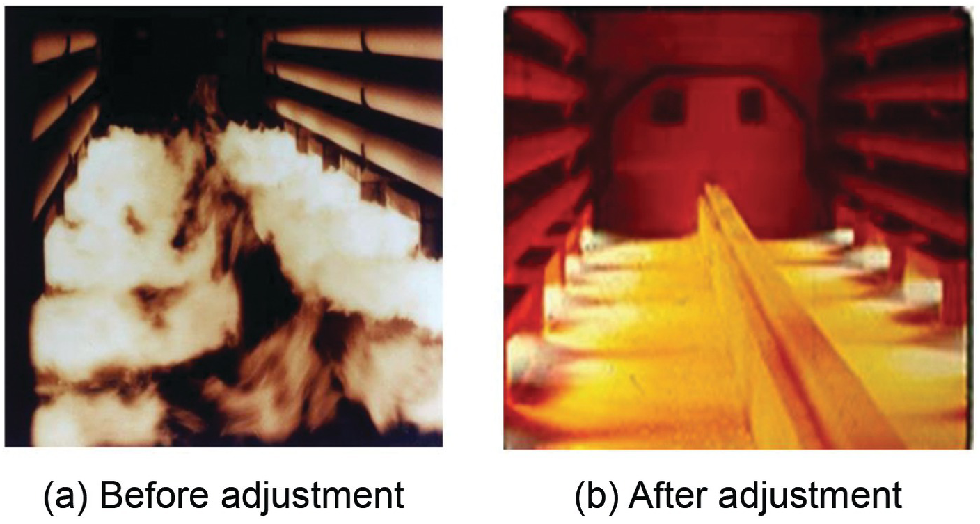
Figure 5.52 Adjusting draft and excess O2 for flat flame burners fired horizontally along the floor of a cabin heater (a) before and (b) after adjustment.
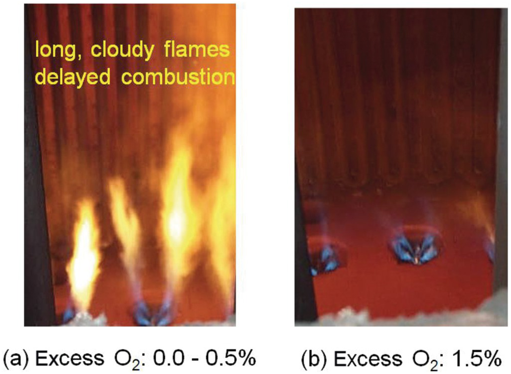
Figure 5.53 Round flame burners firing vertically upward in a vertical cylindrical heater: (a) before and (b) after adjustment.
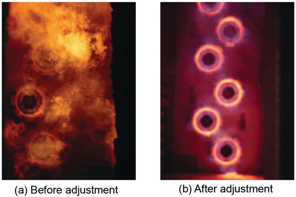
Figure 5.54 Adjusting draft and excess O2 for round burners fired from an end wall of a cabin heater: (a) before and (b) after adjustment.
5.2.2.6 Replacing Burners
Figure 5.55 shows conventional burners firing refinery fuel gas through tunnels horizontally across the floor of a cabin heater. A limiting factor for the firing rate was the maximum refractory temperature along the floor. NOx was approximately 180 ppmvd at 3% excess O2. Figure 5.56 shows a similar furnace after the conventional burners were replaced with ultra-low-NOx burners. Notice the much more uniform refractory temperature, which permitted increasing the firing rate for more production. The NOx was reduced to approximately 20 ppmvd for almost a 90% reduction.
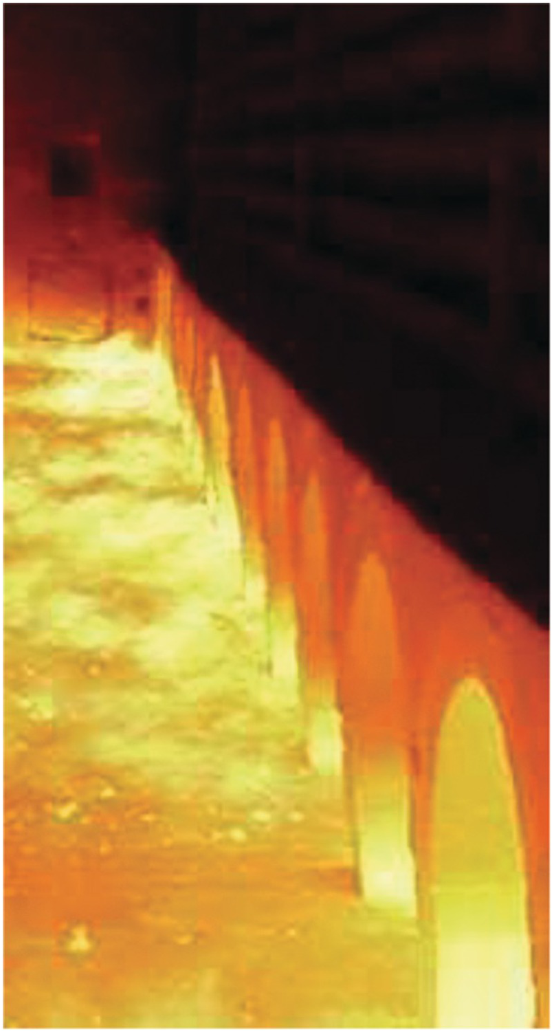
Figure 5.55 Heater with original floor-fired burners before replacement with ultra-low-NOx burners.
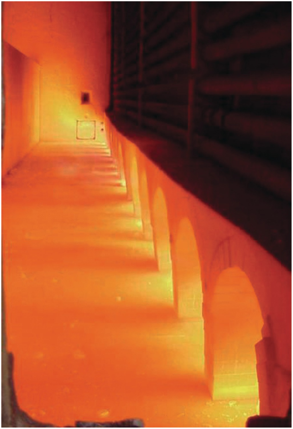
Figure 5.56 Heater after replacement with ultra-low-NOx burners.
5.3 Power Generation
5.3.1 Duct Burners
Duct burners are commonly used in the outlet of stationary gas turbines used for power generation to increase the production for a given size system. The combustion “air” actually consists of the exhaust products from the turbine, which typically contains 11–16% oxygen by volume and is at an elevated temperature of 315–540°C (600–1,000°F). Figure 5.57 shows a grid-style duct burner firing on natural gas. Figure 5.58 shows a side-fired oil burner firing across a grid.
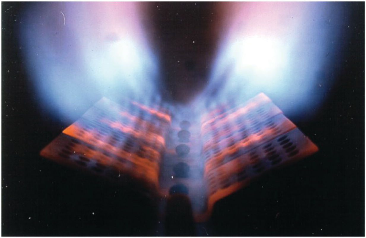
Figure 5.57 Duct burner firing on natural gas.
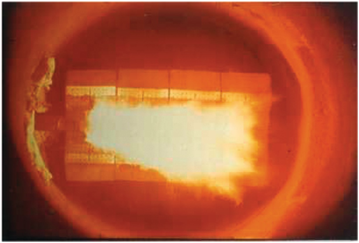
Figure 5.58 Duct burners firing on oil.
5.4 Infrared Heating and Drying
5.4.1 Thermal Radiation Burner
Figure 5.59 shows the firing side of a Marsden Natural Gas Instant On/Off infrared (IR) burner used in a wide range of applications, some of which are included here. The burners operate through a full range of temperature from 1,100°F to 1,850°F (590–1,010°C). A common application is to dry moving webs (sheets) of paper or textiles as shown in Figure 5.60. Figure 5.61 is a schematic of the drying section of a Fourdrinier paper-making machine. The paper is made from a wet pulp slurry that is dried by traveling over steam-heated drums. However, paper is a good insulator, so the drier the paper is, the poorer the thermal conduction and the poorer the thermal efficiency of the steam-heated cylinders. IR burners are effective for enhancing drying near the end of the process because they do not rely on conduction, but rather on penetrating thermal radiation. Figure 5.62 shows an example of that application. A common problem for a Fourdrinier is that it often produces an uneven moisture profile across the width of the paper as determined by optical sensors viewing the high-speed moving paper web. Paper is typically dried to some maximum moisture level. The problem is that some segments of the paper web may be dried to significantly lower moisture levels because of the uneven profile. These drier sections have reduced quality and can cause problems, for example, in copiers and printers. Additionally, paper is sold in part by weight, so removing more water than needed reduces revenue. Figure 5.63 shows an example of a moisture-profiling burner where the firing rate of each segment is determined by upstream moisture sensors. These burners have extremely fast reaction times and can adjust quickly to moisture changes. IR burners can be used to dry coatings on paper. Figure 5.64 shows a 31.5″ × 350″ (80 cm × 890 cm) IR Drying Frame utilizing an emitter to preheat and initiate the evaporation process following the application of water-based coatings. Each Drying Frame transfers a maximum of 3 MMBtu/hr (0.9 MW). The emitters heat up to full power (>1,850°F or 1,010°C) in 5 s and cool to the touch in 1 s to dry the applied coating on lightweight paper. Figure 5.65 shows 11″ × 66″ (28 cm × 170 cm) Marsden IR burners for annealing glass tubes. Each burner has a maximum heat transfer of 217,800 Btu/hr (64 kW).
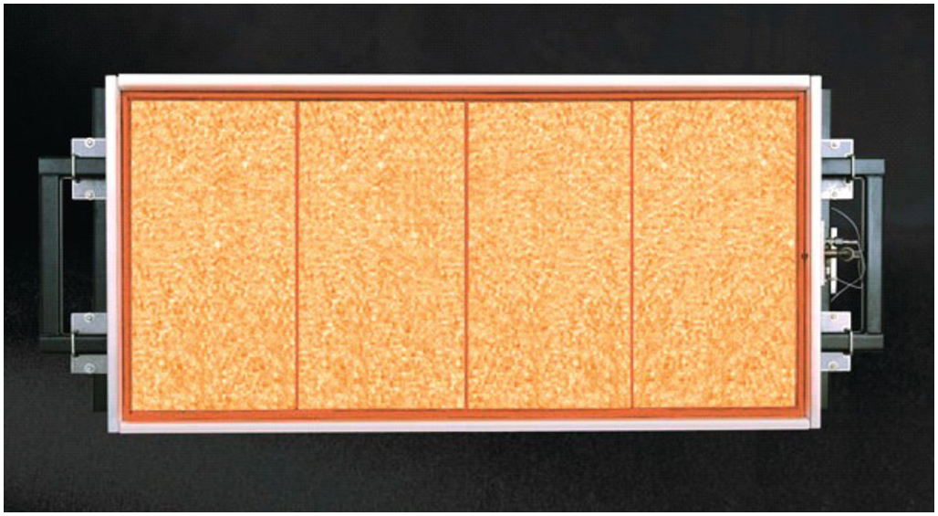
Figure 5.59 Porous refractory burner firing on natural gas.
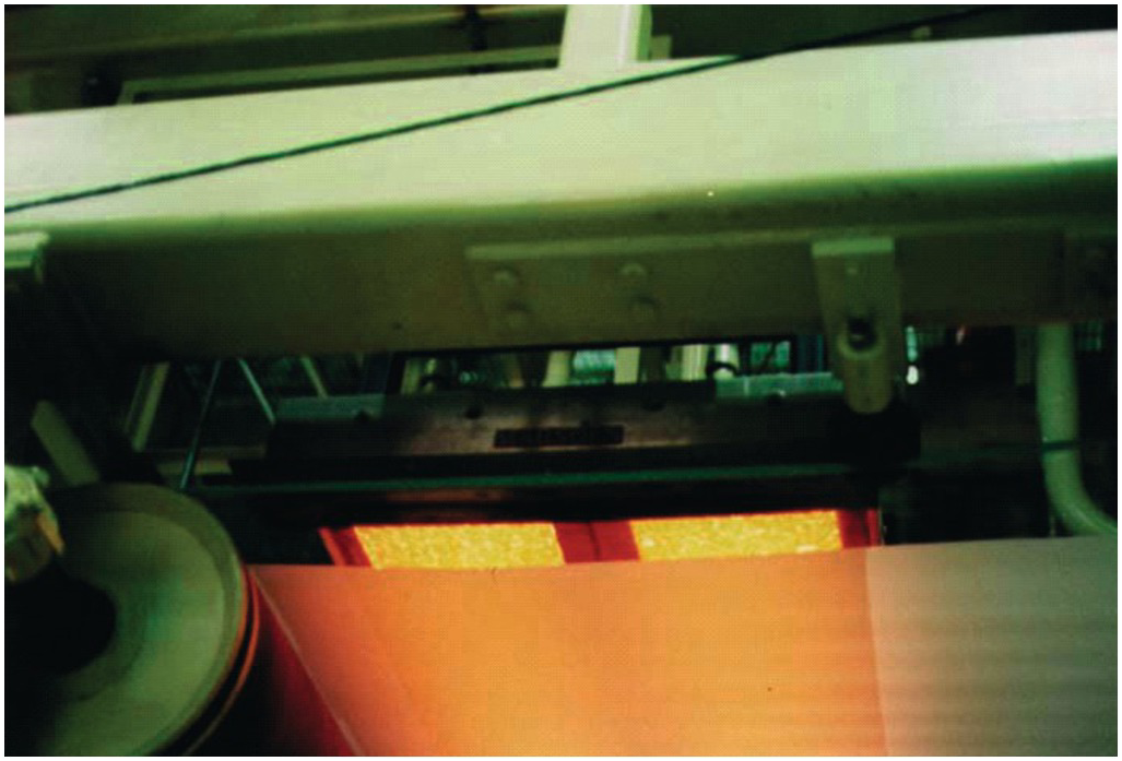
Figure 5.60 Porous refractory burner used to dry textiles.
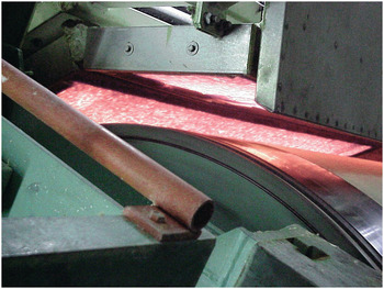
Figure 5.61 Schematic of the drying section of a Fourdrinier paper-making machine using porous refractory burners.
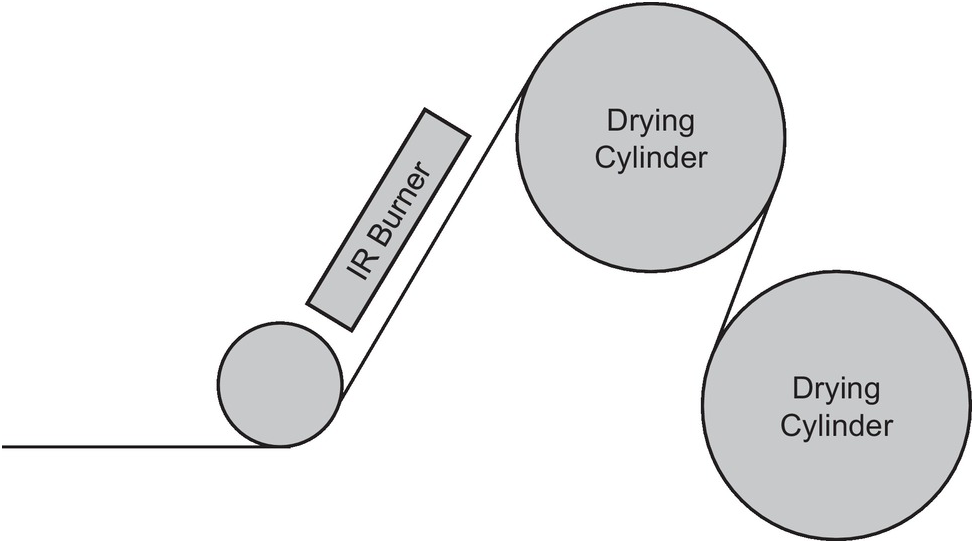
Figure 5.62 Porous refractory burners used to paper.
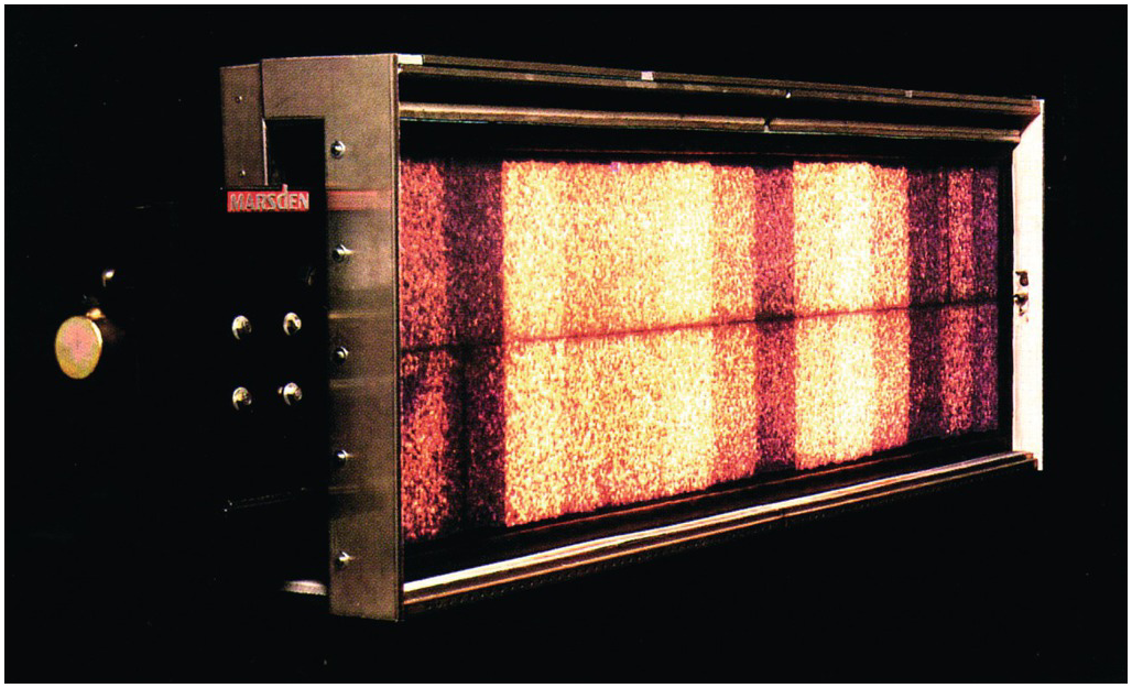
Figure 5.63 Porous refractory burners used in moisture profiling where the firing rate of each segment is determined by upstream moisture sensors.
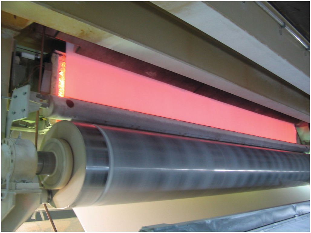
Figure 5.64 Porous refractory burners used to preheat and initiate the evaporation process following the application of water based coatings.
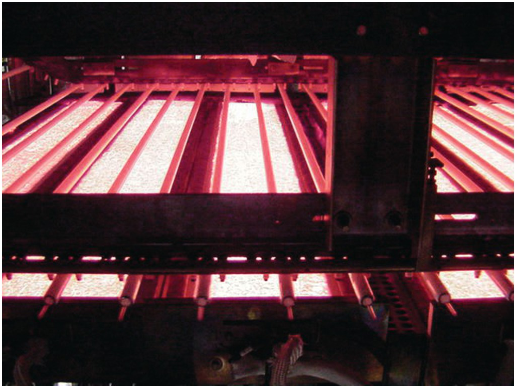
Figure 5.65 Porous refractory burners used to anneal glass tubes.
5.5 Flares
5.5.1 Steam-Assisted Flares
Steam is often used to entrain additional combustion air into flare flames to increase their smokeless capacity when the waste gas is at a relatively low pressure. Figure 5.66 shows a smoking flare before the assist steam has been turned on. Figure 5.67 shows the same flare just after the steam assist has been turned on. Figure 5.68 shows the steam assist at full flow where the smoking has been eliminated.
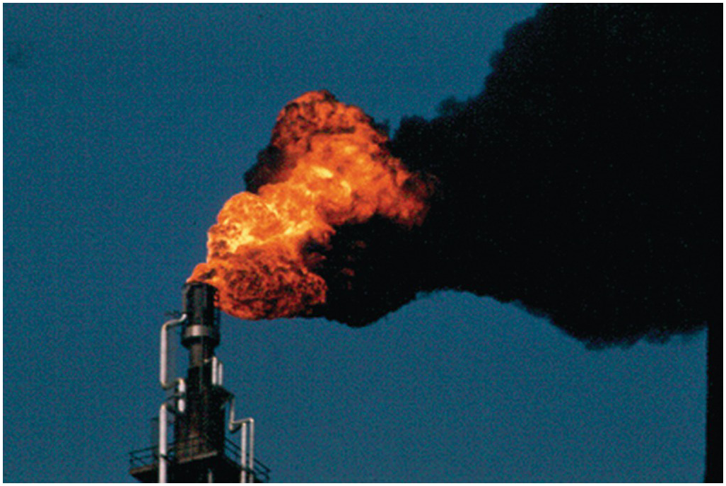
Figure 5.66 Steam-assisted flare with the steam off.
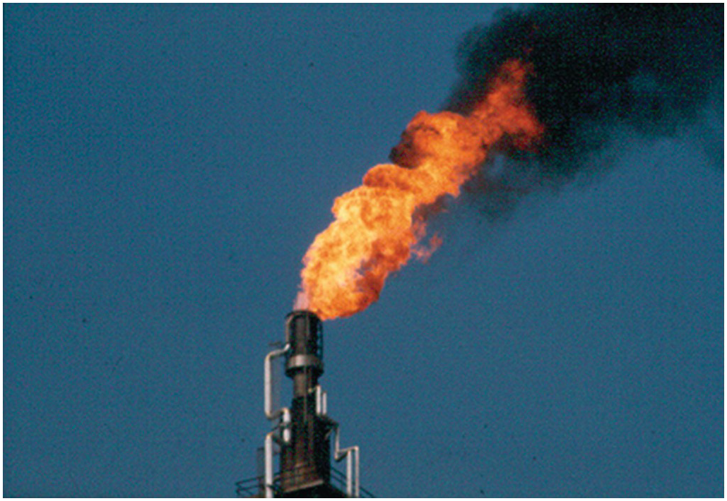
Figure 5.67 Steam-assisted flare with the steam just starting.
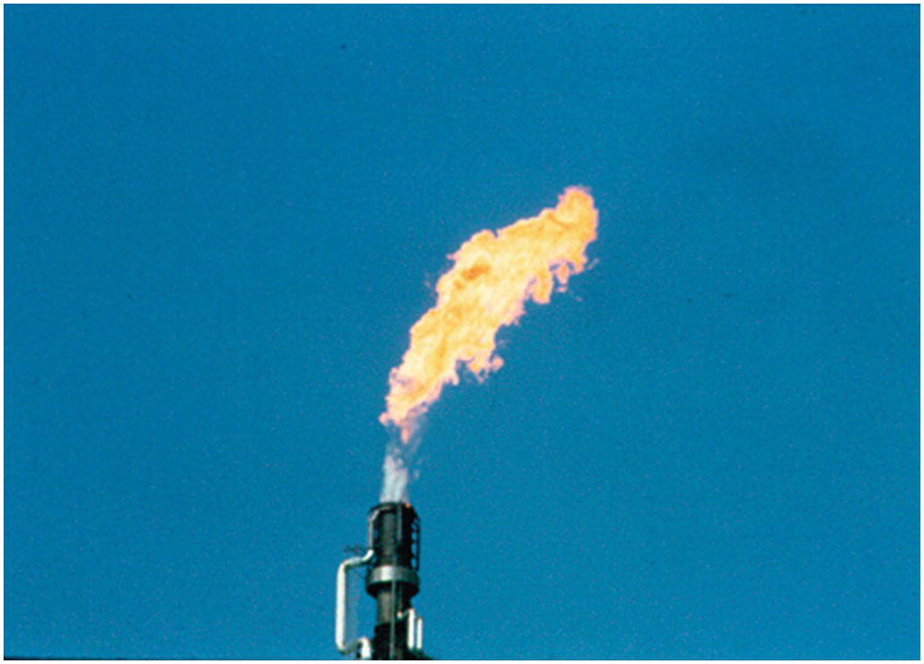
Figure 5.68 Steam-assisted flare with the steam at full rate.
5.5.2 Air-Assisted Flares
Blowers are sometimes used to supply additional combustion air to flares to increase their smokeless capacity when the waste gas is at a relatively low pressure. Figure 5.69 shows a smoking flare before the assist air has been turned on. Figure 5.70 shows the same flare just after the assist blower has been turned on. Figure 5.71 shows the air assist blower increasing its output. Figure 5.72 shows the assist blower at full capacity where the smoking has been eliminated.
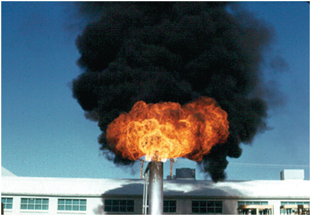
Figure 5.69 Air-assisted flare with the blower off.
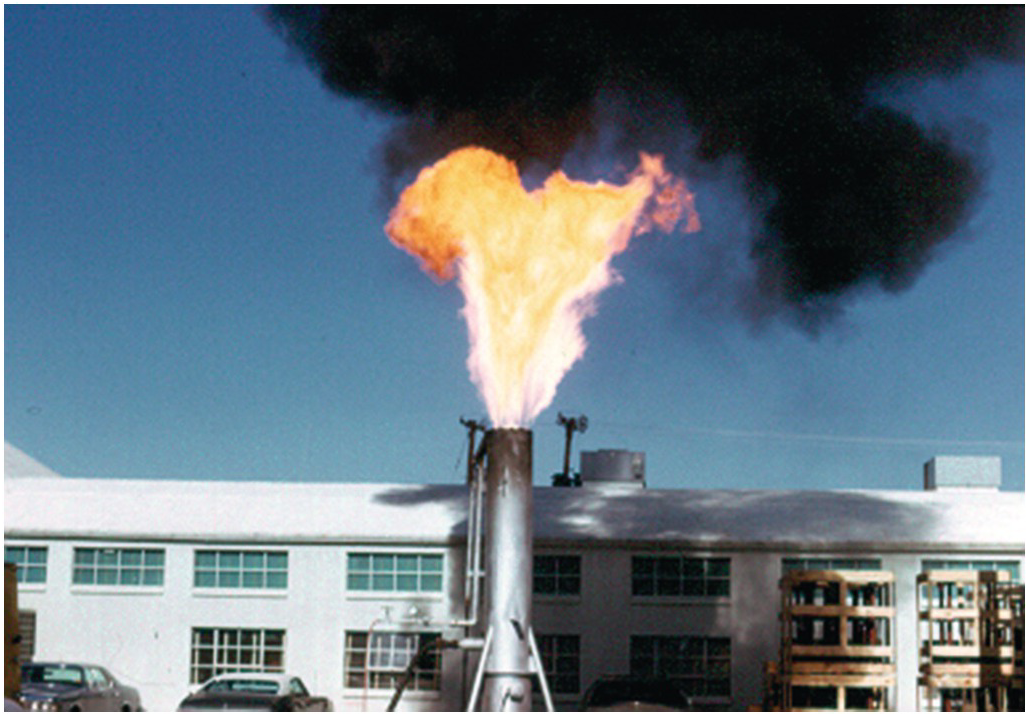
Figure 5.70 Air-assisted flare with the blower just starting.
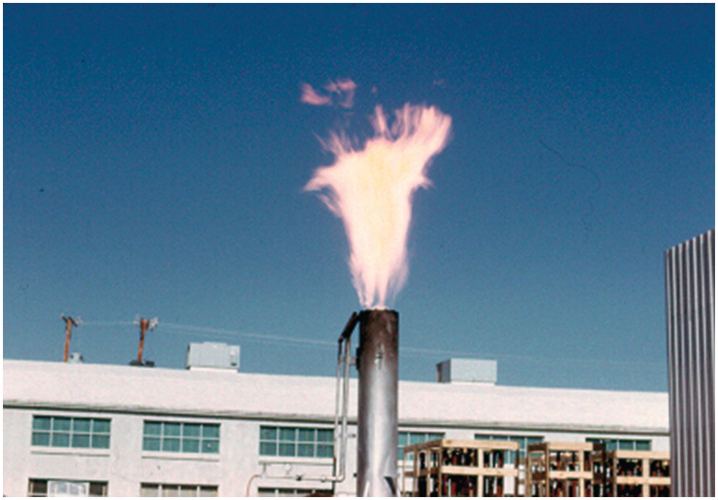
Figure 5.71 Air-assisted flare with the blower speed increasing.
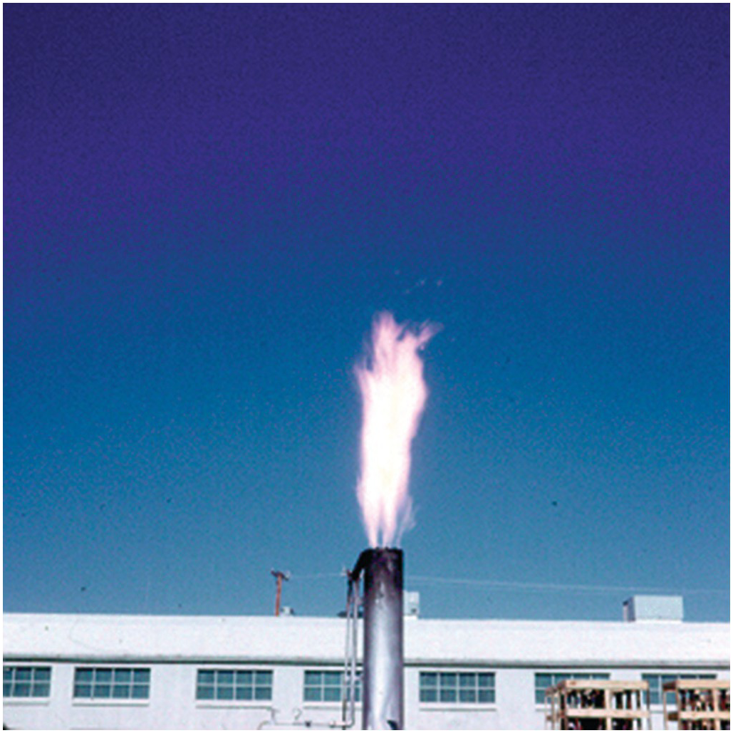
Figure 5.72 Air-assisted flare with the blower at full rate.
5.5.3 Ground Flares
If waste gases are at a high enough pressure, then no assist media such as steam or assist air are needed, so unassisted burners can be used. However, two potential challenges are the very wide flow range that may be encountered and the need to conceal the flames from the neighbors around the plant. These are often accomplished by using many smaller burners in an array surrounded by a fence to substantially hide the flames. Figure 5.73 shows such an array with four rows of burners where more rows of burners come on as the waste gas pressure increases. This permits the burners to fire more optimally at their design capacity. It is desirable to make the array as small as possible to minimize the plot space. Figure 5.74 shows a test of ground flare burners in a single row to determine optimal spacing. If the burners are too close together, the flames will coalesce and become much longer, which is not desirable. If they are too far apart, then the array becomes larger and more costly.
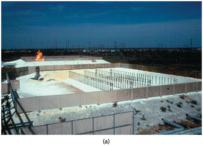

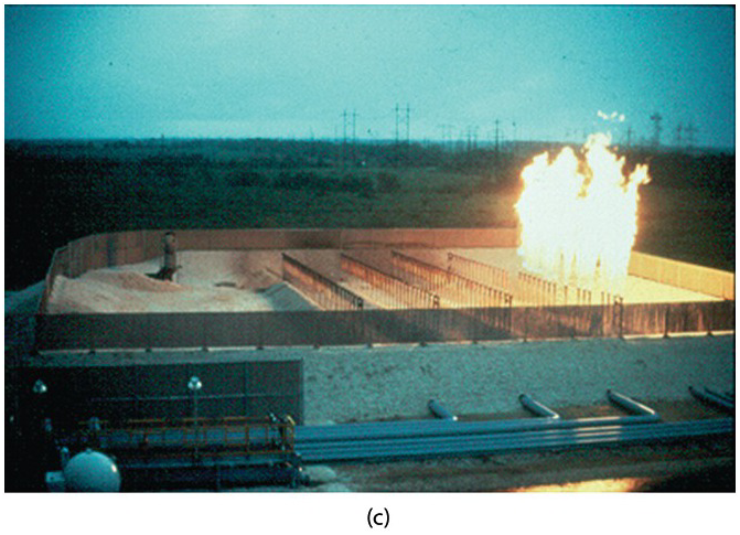
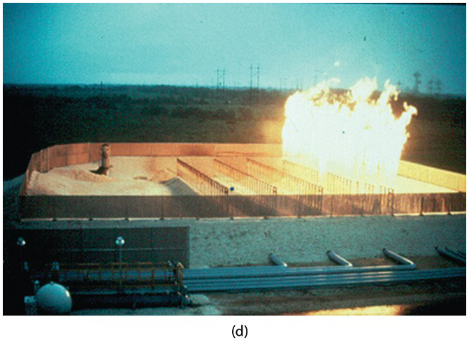
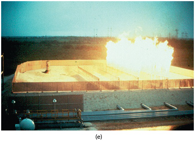
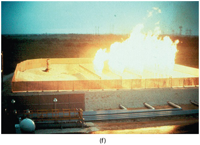
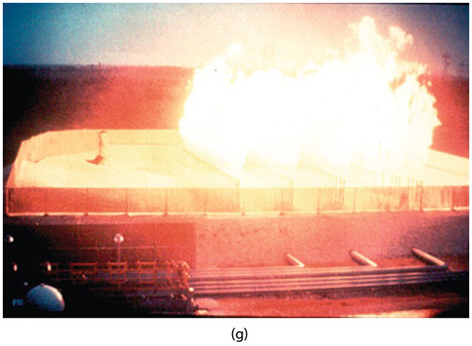
Figure 5.73 Ground flare with (a) no burners on increasing until (g) all burner stages are on.
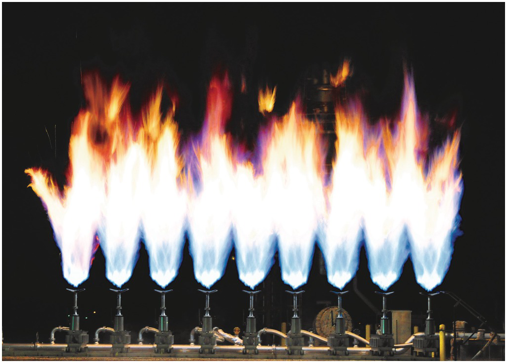
Figure 5.74 Ground flare burner spacing test.
5.5.4 Flare Radiation Reduction
One of the reasons some land-based flares have flames so high above the ground is to minimize the thermal radiation at ground level that could injure people and damage equipment. In some applications it is not feasible to build a tall flare, such as on an offshore oil rig. Figure 5.75 shows one method for minimizing the flare radiation to the platform by having a boom that directs the flame away from the platform. Another method is to inject seawater into the flame where the water reduces the flame temperature and radiation. Figure 5.76 shows such a flare with the water off. Figure 5.77 shows the same flame after the water has been turned on. Notice the significant reduction in flame luminosity with water injection.
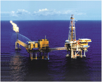
Figure 5.75 Flare radiation on an offshore oil rig.
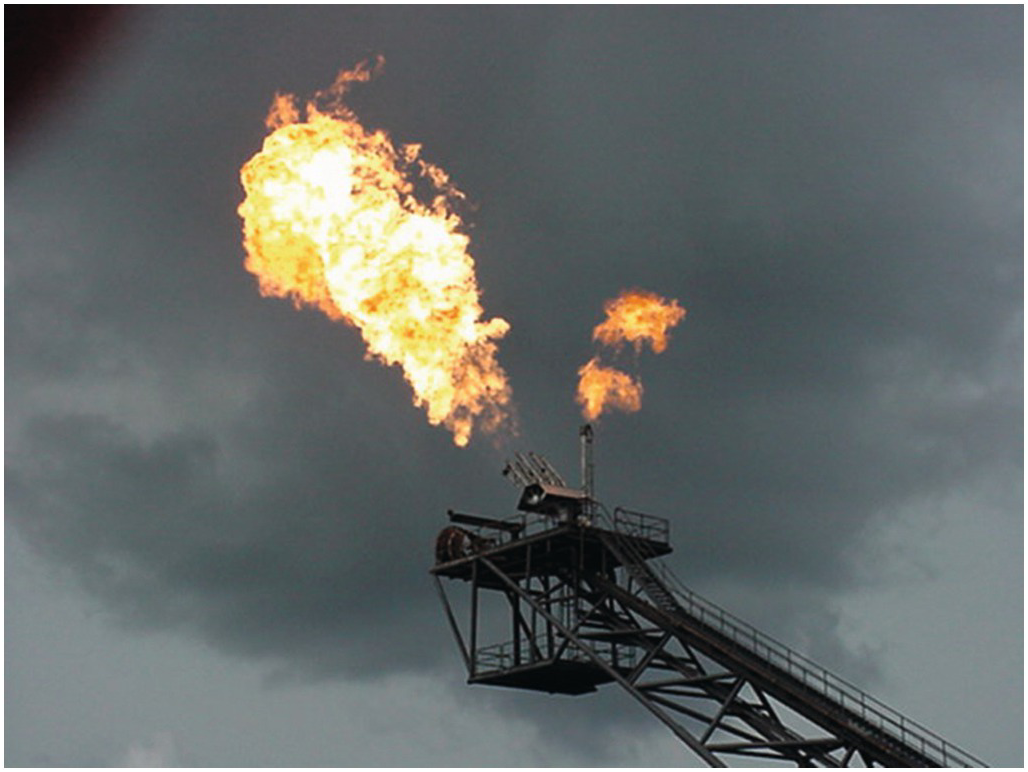
Figure 5.76 Flare without water injection.
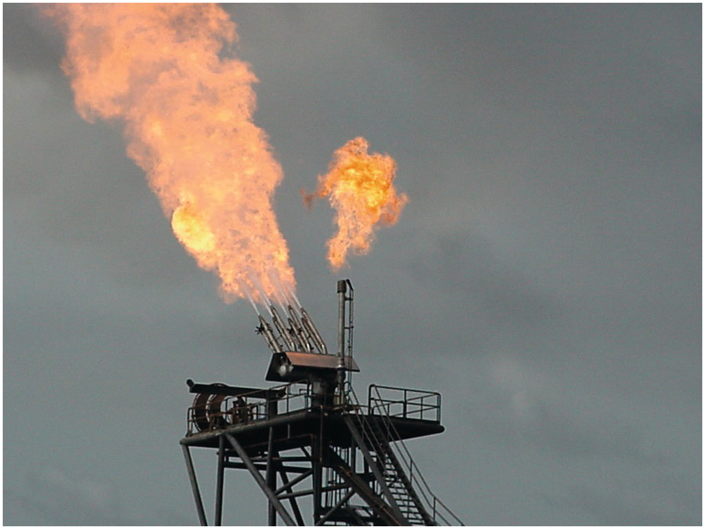
Figure 5.77 Flare with water injection.
5.5.5 Flare Problems
Figure 5.78 shows an example of what can happen when liquid hydrocarbons are not removed from waste products going to a flare designed to handle only gaseous wastes. Much of the liquid falls out and burns on its way to the ground, which is often referred to as flaming rain. Figure 5.79 shows a high-wind condition that can cause a flare flame to pull down on the side of the flare tip, which can lead to equipment damage if this condition is sustained for too long.
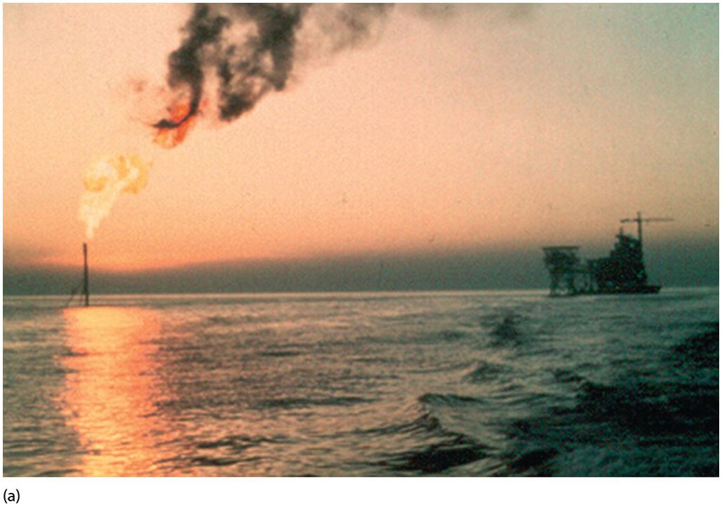
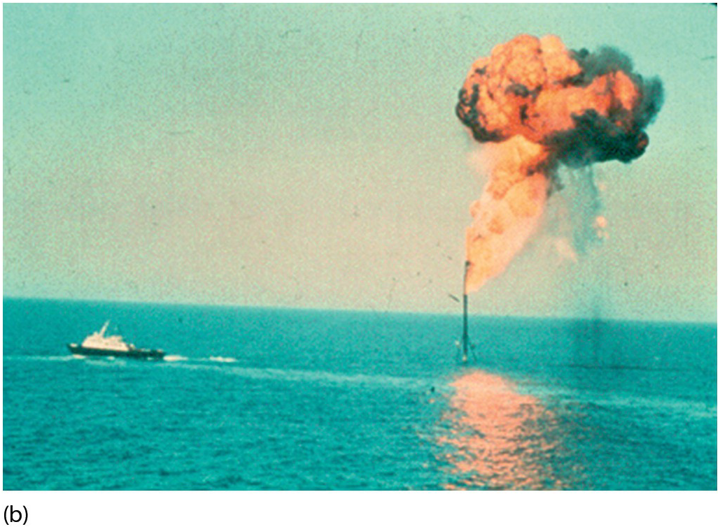
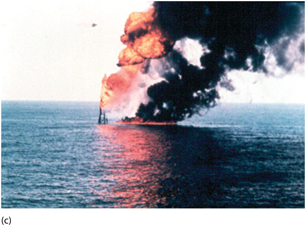
Figure 5.78 Flaring event: (a) start, (b) increasing, and (c) at a high rate.
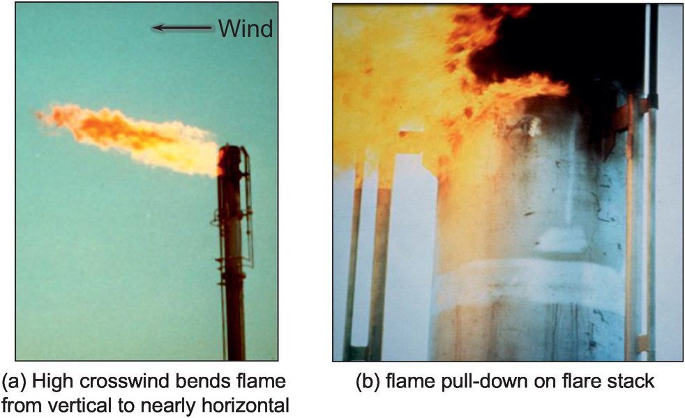
Figure 5.79 Flame pulldown due to high winds.
5.6 Oxygen-Enhanced Flames
For the vast majority of industrial combustion applications, the oxidizer is air (approximately 21% O2 by volume) because of its low cost and availability. However, there are applications where the oxygen content in the oxidizer is higher than 21%, which is often referred to as oxygen-enhanced combustion. The oxygen content can range from 21% all the way to 100% (typically referred to as oxy-fuel. Figure 5.80 shows how the flame structure can vary with the oxygen content in the oxidizer. Figure 5.81 shows an example of oxy-fuel flames used to polish glass. Figure 5.82 shows flameless oxy-fuel technology.
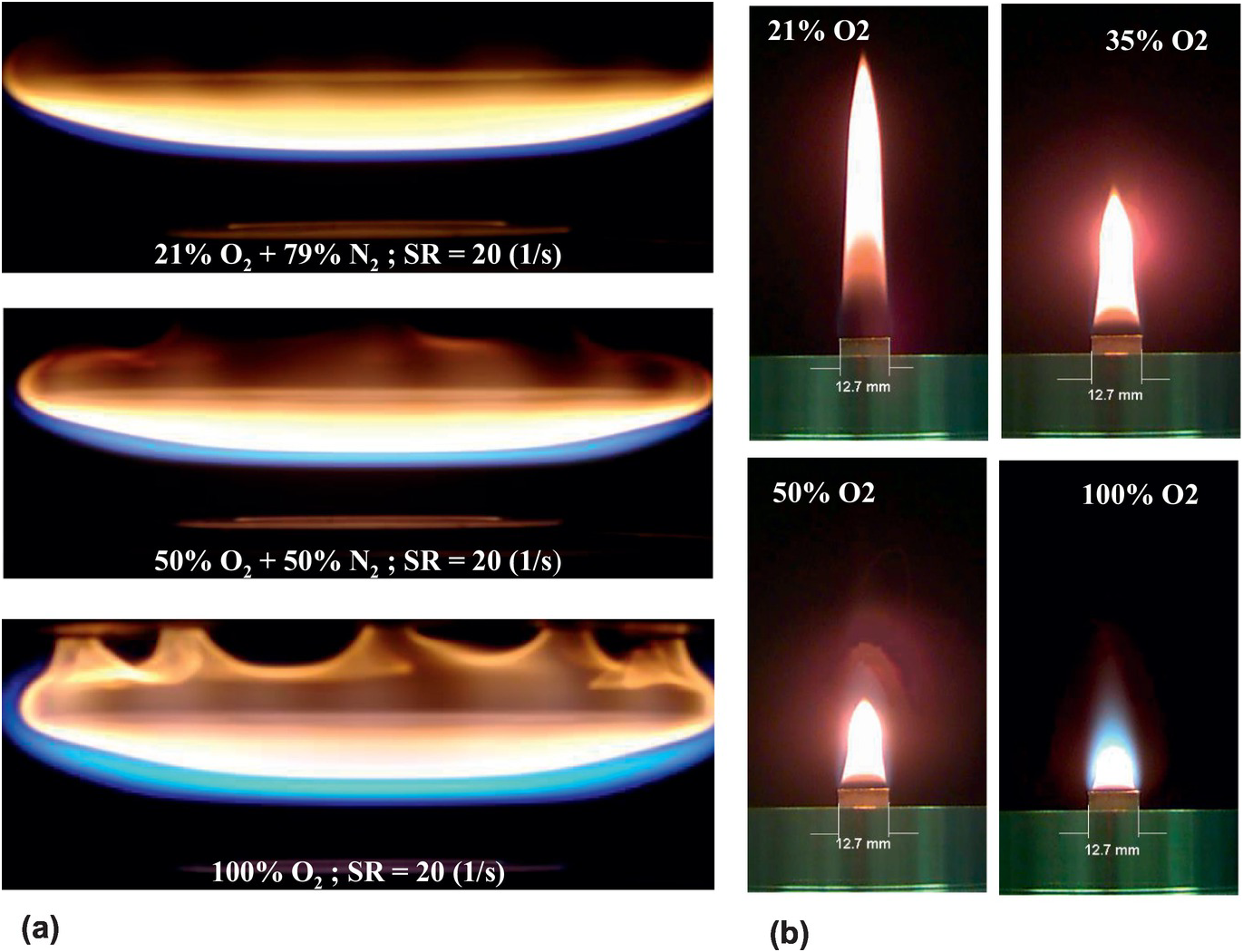
Figure 5.80 (a) Representative photographs of counterflow methane flames formed at various oxygen contents (21–100% O2); (b) display methane co-flow flames formed by varying the oxygen content in the oxidizer from 21% to 100% O2. Both flames are composed of two flame zones – a yellow zone and a blue zone.
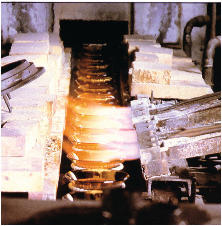
Figure 5.81 Oxy/fuel flames used in glass polishing.
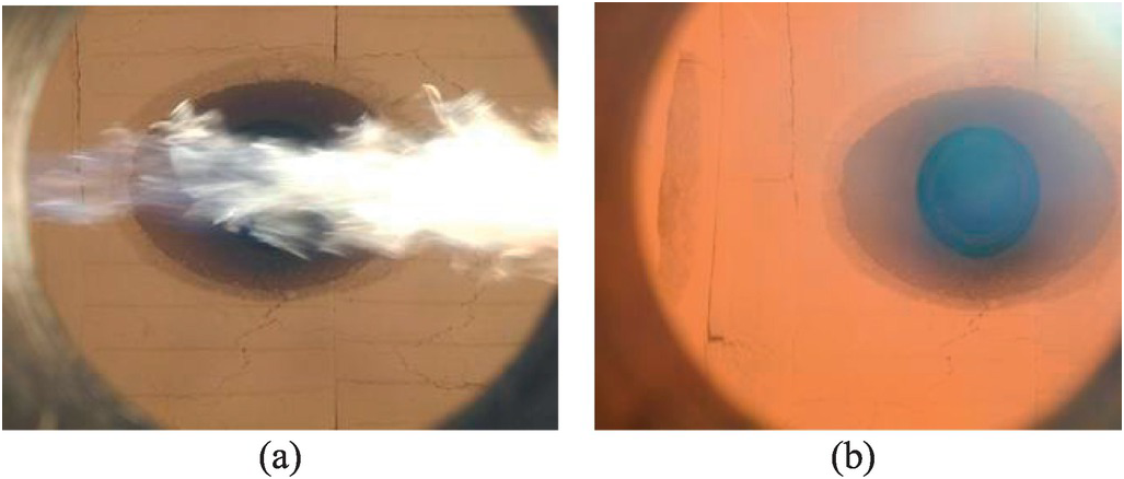
Figure 5.82 Flameless oxy/fuel technology.