Abstract
Scientists have long studied fire in an effort to both understand the world around them and to prevent the destruction and devastation that uncontrolled fires can cause. Despite many advances in the understanding of fire phenomena, society offers continued challenges that require new approaches for the prevention and mitigation of unwanted fires. In this chapter, fire research is presented through a series of photographs that scale from small, buoyant flames in the laboratory up to large, uncontrolled wildfires and even fire whirls.
Introduction
Scientists have long studied fire in an effort to both understand the world around them and to prevent the destruction and devastation that uncontrolled fires can cause. Despite many advances in the understanding of fire phenomena, society offers continued challenges that require new approaches for the prevention and mitigation of unwanted fires. In this chapter, fire research is presented through a series of photographs that scale from small, buoyant flames in the laboratory up to large, uncontrolled wildfires and even fire whirls.
Our journey begins with a study of the most canonical problem in fire science, the pool fire, where liquid fuel in a pan is burned in a quiescent atmosphere. Interesting effects such as puffing and flickering are explored, as well as the influence of different fuels and configurations. Simulations of a pool fire show the complex instabilities that govern its behavior. Similar behavior is shown in very large fires, here up to 120 m in diameter. Another canonical problem in fire, upward flame spread, is presented in comparison to other drivers of the flame-spread process: orientation, ambient wind, and configuration. Together, the heat-release rate from a fire and flame-spread rate form the primary descriptors of material flammability, signifying the safety and appropriateness of materials for fire-safe design.
When design fails and accidents occur, active suppression of fires, often with water, is all important. Fire suppression over a range of scales, from a single droplet to large sprinklers, is explored. The extinction process is shown using a unique line burner that slowly transitions to extinction as nitrogen is added to the surrounding flow. A dramatic intensification of combustion, fire whirls, is also presented, occurring when appropriate levels of swirl are added to a pool fire. They result in a dramatic increase in flame length, heat release, and, in nature, unpredictable fire behavior. The efficiency of this process and its potential application for remediation and energy production are presented through the “blue whirl,” a soot-free regime of the fire whirl.
Larger uncontrolled fires, namely wildland fires, are also presented. In the laboratory, experiments using laser-cut fuelbeds have been studied in an effort to understand the processes controlling wildland fire spread. Also shown are firebrands, small burning embers that loft off burning material and cause much of the home destruction observed in wildfires. Large fires have also occurred in cities, and a recreation of the Great Fire of London of 1666 that occurred on the Thames in 2016 is a fantastic illustration of the destruction that has occurred in urban areas around the world.
Finally, the slow oxidation of carbonaceous material known as smoldering is presented. While it does not have a flame, the combustion process is critically important for biomass burning and the production of emissions from many different landscape-scale fires, impacting public health and the global climate.
As Michael Faraday once said, “There is no better, there is no more open door by which you can enter into the study of natural philosophy, than by considering the physical phenomena of a candle.” This journey through fire presents only a brief introduction to many captivating features encountered in the study of fire phenomena.
6.1 Pool Fires
6.1.1 Puffing Pool Fires
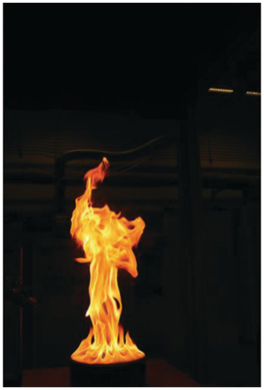
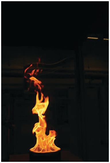
Buoyant diffusion flames, known as pool fires, form when a pool of liquid fuel is ignited. One interesting feature of pool fires is that they are known to “puff” at characteristic frequencies, on the order of 1 Hz, dependent on the diameter of the pool. In these photos two cycles of “puffing” are illustrated, where parcels of hot gas are formed at the base and transported upward, before the fire necks back in and the cycle begins again.
6.1.2 Synchronizing Twin Flickering Flames
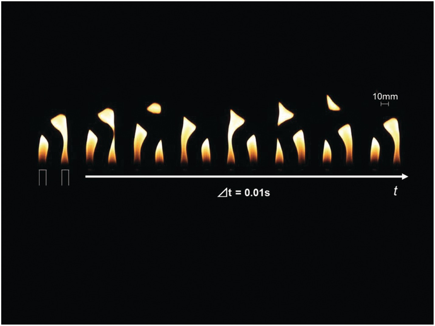
Diffusion flames at a certain scale under a gravimetric field produce periodic motions caused by a buoyancy-induced instability: this is what we call flickering. We examine what happens when twin flickering flames are placed at a prescribed distance from one another. Interestingly, both in-phase and out-phase harmonic oscillation of twin methane–air jet flames (10.6 mm inner diameter of burners, issuing methane at 500 cm3/min) are found when the distance is modified. These images were taken with a high-speed camera (CASIO EX-F1 at 100 fps) at a distance of 25 mm, at which the out-phase mode with 13 Hz of flickering frequency is dominant. Left and right flames are elongated and their tips are separated in turns, making it look like the flames take turns jabbing at one another.
When the separation distance is set to smaller than 25 mm, twin flames merge together and show an in-phase oscillation. When it is larger than 25 mm, on the other hand, the oscillation mode suddenly switched to an out-of-phase one as shown in this figure. Interestingly, what is seen at 25 mm distance is that twin flames temporarily cease to suppress the buoyancy-induced instability together. In this way, we can study what causes this buoyancy-induced instability and how to suppress it if necessary.
Acknowledgements
This research was supported by Toyota Physical and Chemical Research Institute for fiscal year of 2015.
Source Reference
Other Relevant Reference(s)
6.1.3 Emulation of Pool Fires with a Gas Burner
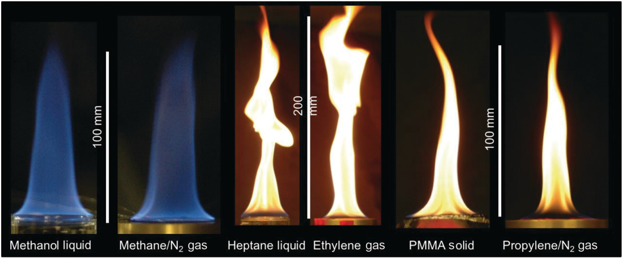
Studying the combustion of condensed fuels can be difficult, so researchers often attempt to “emulate” these flames. In each pair of images shown, the flames of condensed and gaseous fuels have the same heats of combustion, heats of gasification, surface temperatures, and laminar smoke points. When these four quantities are matched, the resulting diffusion flames have similar appearances. The burner used here has been designed to eventually study flames in microgravity.
References
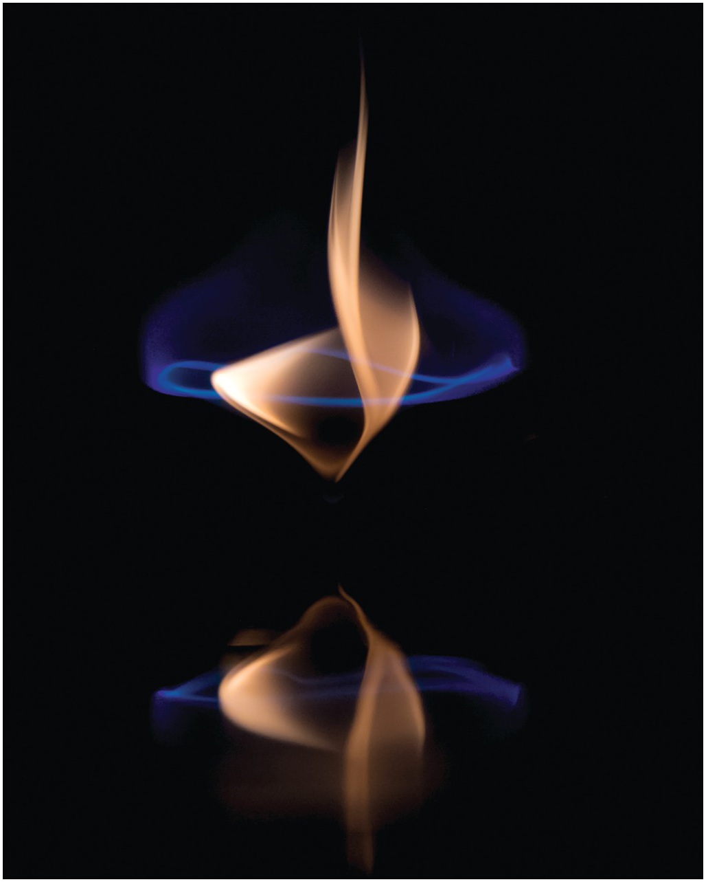
6.1.4 Methanol Pool Fire
Pool fires have a complex structure, originating from the base upward into the plume. When burning methanol, little to no soot is produced, so the flame appears blue and structures can be clearly visualized. In this sequence of images, a pool of methanol ignited. The flame first is observed to propagate rapidly over the liquid fuel surface. Once the entire surface is ignited, a series of structures can be observed around the base of the pool fire, which play a complicated role in its structure and behavior.
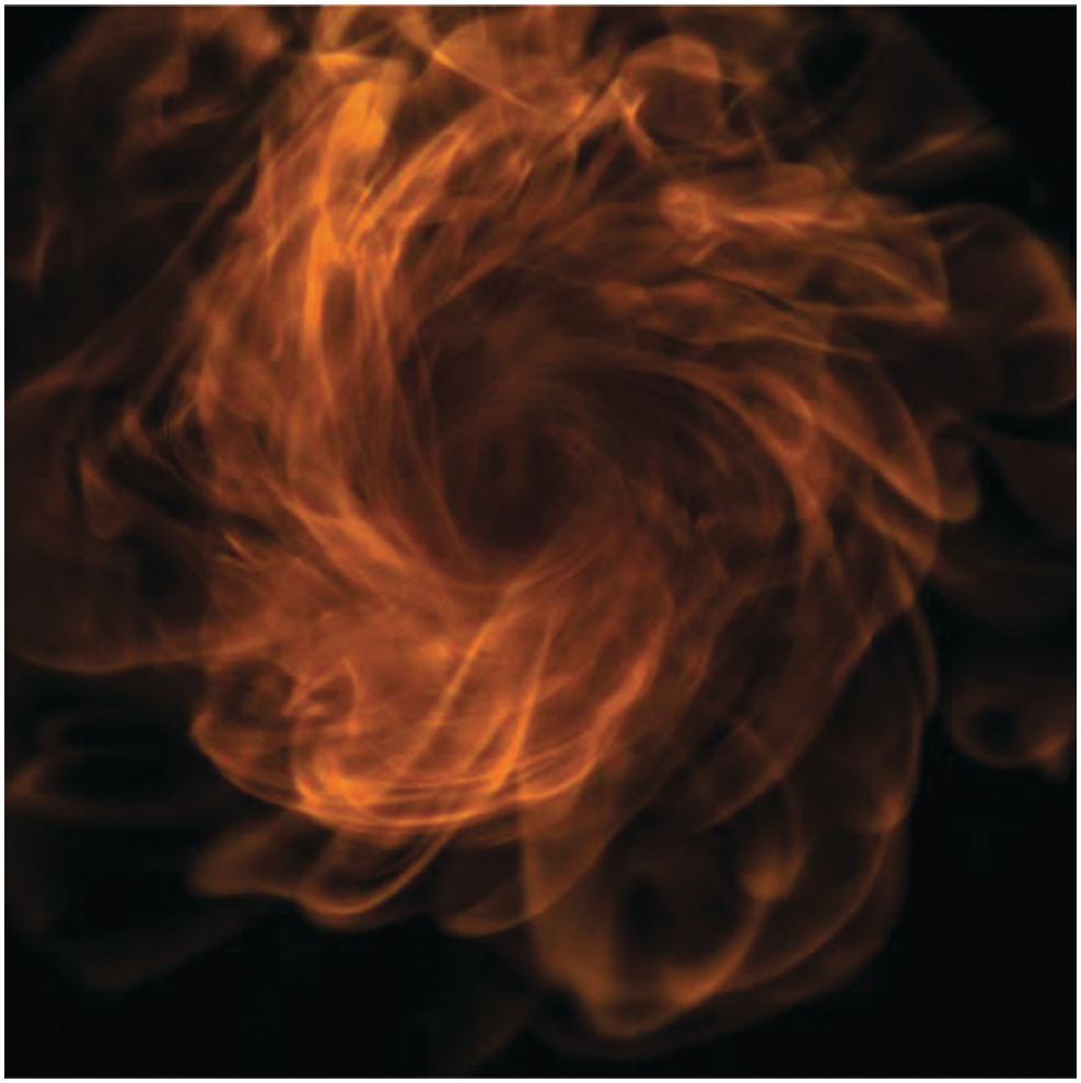
6.1.5 Simulation of Pool Fire Dynamics

This graphic depicts the turbulent instability dynamics of a 1 m-diameter methane–air fire plume. Instability dynamics are responsible for the unsteady heat transfer in fire environments, which have been observed experimentally. The mesh superimposed on the bottom of the plume is the underlying computational grid utilized to carry out the calculation. The puff cycle of the plume may be broken down into four distinct stages: formation of a base instability near the edge of the plume; growth of the instability due to a misalignment of the vertical pressure and radial density gradients generating a localized torque; formation of a large toroidal vortex that self-propagates and entrains a large quantity of surrounding air; and destruction of the toroidal vortex due to formation of secondary instabilities that grow causing a nonlinear breakdown of the toroidal vortex. The baroclinic torque instability dynamics is an important ingredient in characterizing the fire dynamics of large pool fires as it dictates the level of air entrainment and flame surface area available for combustion. An improved understanding of instability dynamics will therefore result in more accurate predictions of fire intensity and growth.
Acknowledgements
This research was supported by the National Science Foundation under grant CTS-0348110 and the Office of Naval Research under Grant No. N00014-03-1-0369. Computer resources were provided by the Center from Computational Research (CCR) at the University at Buffalo, the State University of New York.
Source References
Other Relevant Reference(s)
6.1.6 Extremely Large-Scale LNG Pool Fires and Indoor Fire Whirls

Figure 6.15 Largest experimental LNG pool fire on water (56 m-diameter, 146 m height) at Sandia National Laboratories, Albuquerque, NM.

Figure 6.16 Largest indoor experimentally created fire whirl (3 m-diameter pool) at Sandia National Laboratories, Albuquerque, NM.
While many experiments are conducted in the laboratory, it is important to verify and explore fire dynamics on a larger scale, where fire presents its greatest hazards. A large-scale liquefied natural gas fuel fire experiment simulating a spill of fuel on water was conducted at the 120 m-diameter water pool at Sandia National Laboratory, Albuquerque, New Mexico, on December 10, 2018. Other photos show an experimentally generated fire whirl formed from a 3-meter diameter JP-8 test conducted in the FLAME facility at Sandia National Laboratory.
6.2 Flame Spread and Fire Growth
6.2.1 Surface Inclination Effects on Upward Flame Spread

Flame spread, the process of fires moving over a surface, occurs due to ignition of virgin material as a result of heating. There are many mechanisms of flame spread, which vary depending on the materials, geometry, conditions, and scale under investigation. Changes in the rate of flame spread, and the nature of the flame, are easily visualized by changing the orientation of the fuel. Starting from the left “ceiling fire,” as the inclination angle or tilt of a burning surface is increased, underside flames transition from blue, well-mixed laminar flames to increasingly turbulent yellow flames on the topside that “lift” from the surface, dramatically increasing the flame thickness. These images were taken perpendicular to the surface of a thick sample of Polymethyl Methacrylate mounted flush into insulation board as flames spread upward. These tests have helped in finding critical inclinations with maximum flame spread rates, burning rates, and heat fluxes from the flame.
Reference
6.2.2 Wind-Driven Fires
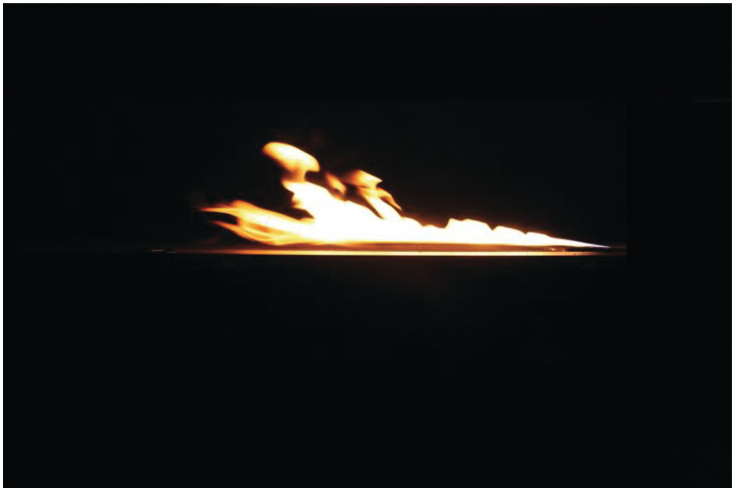
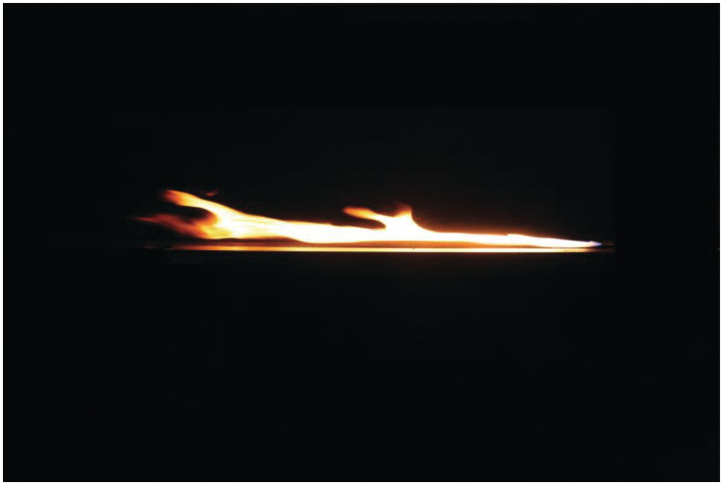
Changes in ambient wind, similar to slope, have a drastic affect on the spread rate of a fire. This series of images show the effect of wind (from 0.87 to 2.45 m/s) on a stationary flame, simulated using a 9.5 kW gas burner. As the wind, blowing from right to left, is increased, the fire transitions from more of a plume-dominated mode to an attached, boundary-layer flame. As flames become attached to the surface, heating and thus their rates of spread increase.
Reference
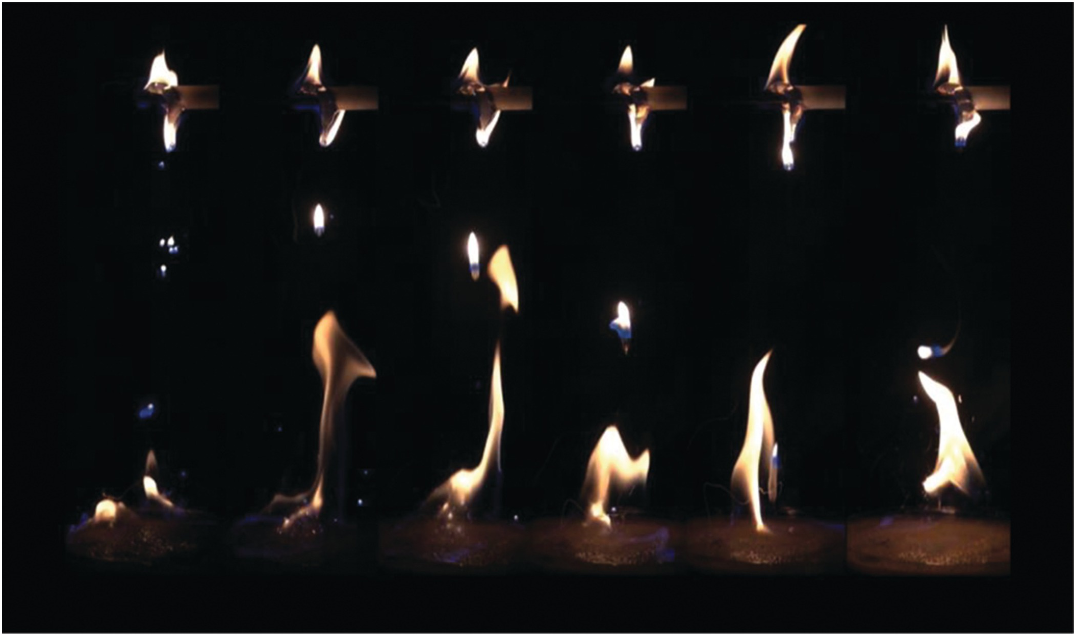
6.2.3 Asymmetric Buoyancy Induced Blow-Off
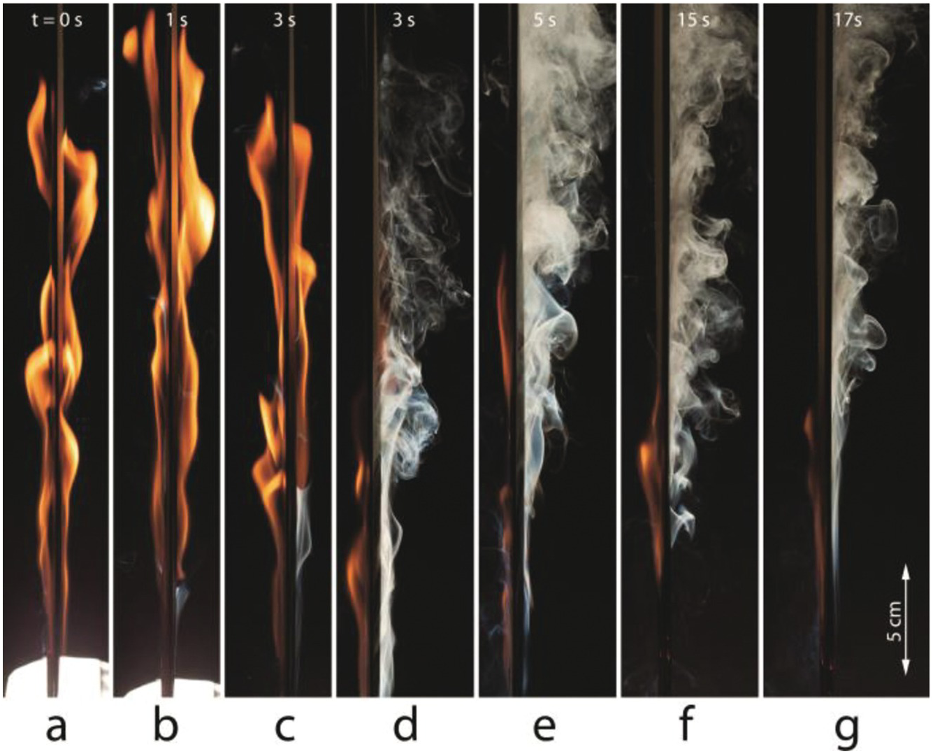
A 5 cm-wide × 20 cm-long composite fabric sheet woven with thread made of 75% cotton and 25% fiberglass is hung vertically and is electrically ignited at the bottom surface to cause a flame to spread upward. When burned, the cotton is pyrolyzed into fuel vapor leaving behind a woven fabric made only of fiberglass. This remaining fiberglass maintains the integrity of the fabric and acts as a flame barrier that does not allow ignition to penetrate it.
The image views the hanging fabric from the narrow edge. As the flame grows in size after ignition, the incoming air velocity induced by buoyancy becomes too high to remain stable. Image (a) shows the maximum flame length of about 20 cm after ignition and initial flame growth. (b) The flame base on the right-hand side is beginning to blow off due to the high velocity of the entrained air. (c) The flame base on the right-hand side continues to blow off, while the flame base on the left-hand side is maintained. Because the fuel is thermally thin, the left-hand side flame continues to vaporize fuel on the right-hand side, seen as white smoke. (d) The right-hand side flame has been blown too far downstream. The material surface is still too cold in this region for the flame base to be stable in this position. (e) The right-hand flame has completely blown off. A large amount of fuel continues to vaporize from the surface. (f) Due to the reduced fire power and heat feedback to the fuel, the left-hand flame shrinks in length. (g) The left-hand flame reaches its final stable length. As the cotton fuel burns out, this flame slowly propagates upward across the entire surface toward new fuel, but at this reduced length of about 10 cm. The remaining flame will not blow out due to the reduced entrained velocity. The fuel vapor mixing itself with air on the right-hand side is still flammable but is not reignited by the left-hand flame because of the flame barrier properties of the remaining fiberglass fabric.
Acknowledgements
This research was supported by NASA and Underwriters Laboratories.
Reference
6.2.4 Small-Scale Corner Fire

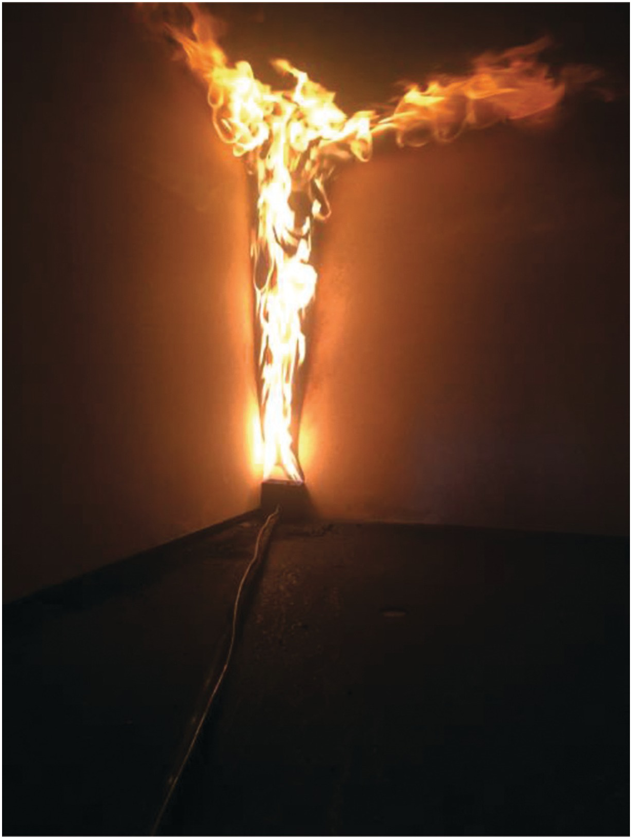
The photo shows a turbulent diffusion flame from a 0.1 × 0.1 m2 sandbox propane burner placed in a corner in a 1/3-scale ISO 9705 room. The heat release rate was measured with the oxygen depletion method to approximately 30 kW. The test setup is used in educational and research activities at the Division of Fire Safety Engineering at Lund University, Sweden.
Corner fires are used to evaluate the fire characteristics of combustible lining materials in standardized tests like ISO9705. Fires that interact with a wall or corner with combustible linings will in most cases result in a more rapid fire spread and shorter time to flashover than if no such interactions are present. The heat flux to the linings will be due to both the exposure fire and the room environment. Furthermore, the mean flame height will be longer when the fire is next to a wall or in a corner because less air can be entrained; this results in the fuel having to travel a longer distance to become fully combusted.
Acknowledgements
Stefan Svensson, Reader at the Division of Fire Safety Engineering, is gratefully acknowledged for his assistance when the test was performed.
6.2.5 Progression of a Compartment Fire
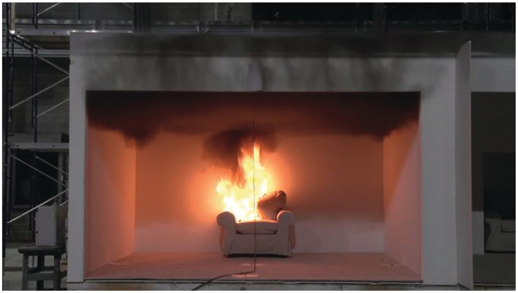
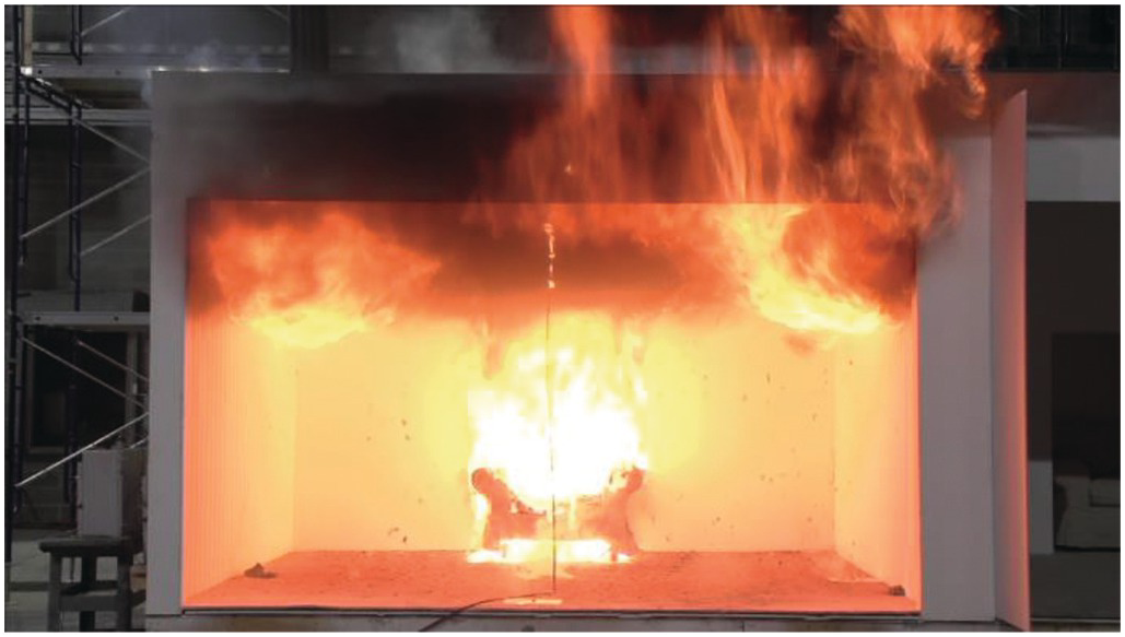
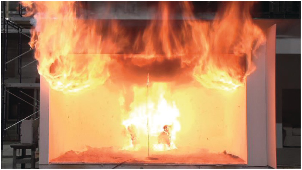
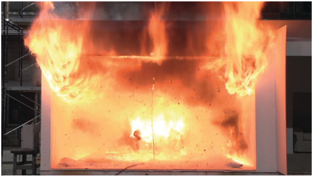
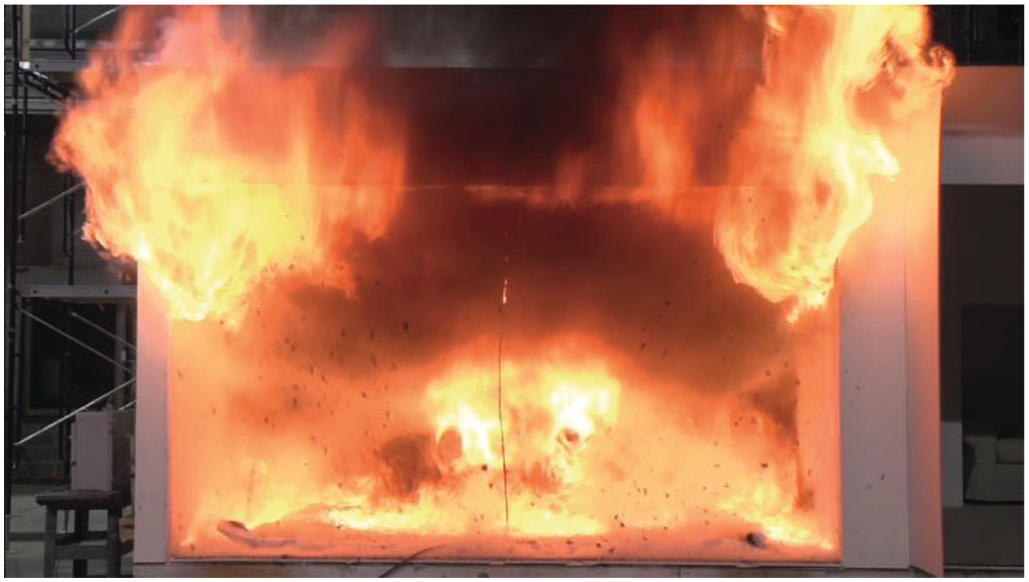
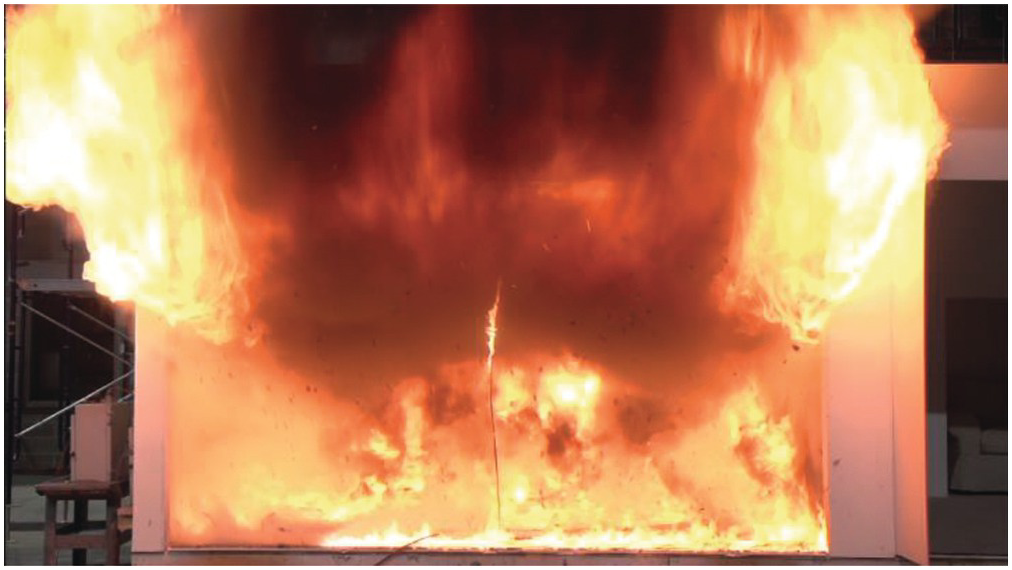
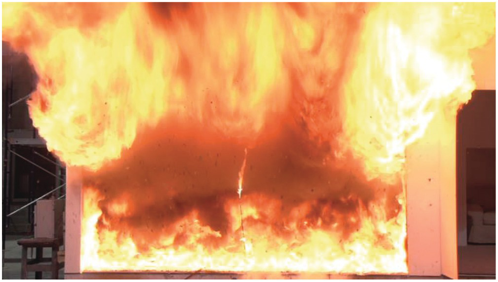
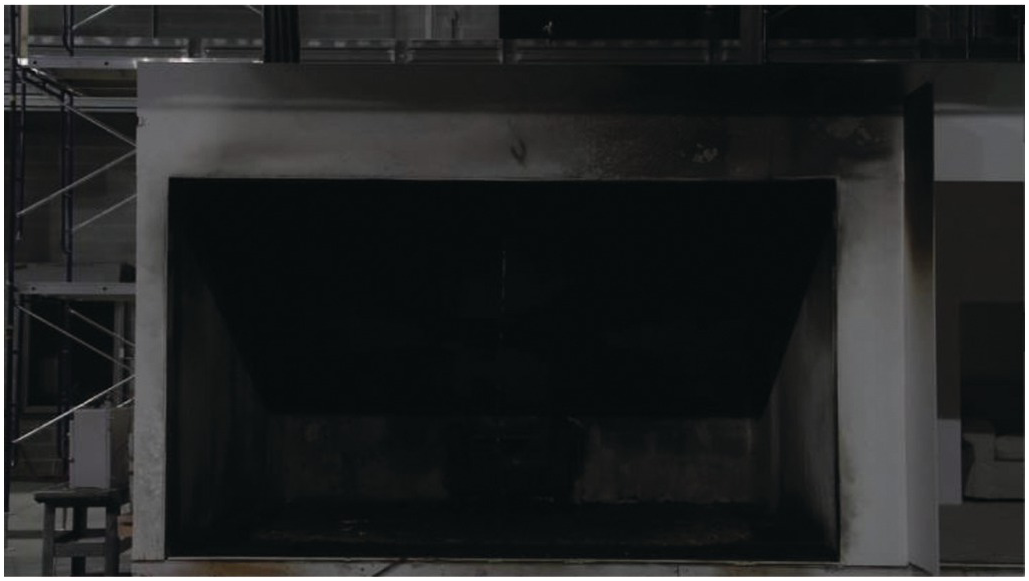
An oversized chair, consisting of mostly polyurethane, was ignited by an FRL “Standard Ignition Package.” The chair was placed into a flashover cell that contained only carpet at the floor with gypsum wallboard walls and ceiling. The fire on the chair was allowed to grow, eventually developing a thermal layer at the ceiling sufficient for flashover conditions. Figures 6.26–6.34 are a series of images demonstrating the development of this compartment fire.
6.2.6 Melting and Dripping during Flame Spread over Wires

Dripping of molten fuel can change fire behaviors, ignite nearby materials, and expand fire size. Dripping occurs when gravity overcomes the resistance from surface tension and viscous forces. It involves a complex phase-change process and is most common in fires of electrical wires and heat insulation materials. The image shows the dripping of molten polyethylene insulation in an electrical wire fire. Dripping first ignited the sand soaked with alcohol, and then started to frolic (interact) with the puffing pool fire. The whole process lasted less than 0.2 s, and was captured by a high-speed camera (500 fps).
6.2.7 Ceiling “Blooming” Fire

The image presented is an experimental flame photo captured from a propane fire beneath the ceiling generated from a stainless circular burner (diameter: 0.06 m, gas exit velocity: 0.015 m/s, heat release rate: 15.3 kW, source Reynolds number: 203). The circular burner was installed at the center of the ceiling with the outlet downward and flush with the ceiling. The ceiling was made from mica board with a low thermal conductivity of 0.035 W/(m K) and good thermal resistance performance. The fuel gas was discharged downward with pure propane as the fuel and air as the oxidizer, which is diffusing with fuel to produce a diffusive flame. The entire apparatus was located in a still air environment at standard pressure. The picture is obtained by a CCD camera with 1/180 s exposure time. This beautiful “blooming flower” flame is broken up into “petals” whose sizes increase during “blooming” from the center. Such gorgeous “blooming fire” is not only esthetically attractive but also a physical nature of buoyant thermal-diffusive instability, whose characteristic length scale can be well viewed from the “petal” sizes. It is this kind of beauty that drives our fascination with the art of fire.
Acknowledgements
This work was supported jointly by Key project of National Natural Science Foundation of China (NSFC) under Grant No. 51636008, Excellent Young Scientist Fund of NSFC under Grant No. 51422606, the Newton Advanced Fellowship (NSFC: 51561130158; RS: NA140102), Key Research Program of Frontier Sciences, Chinese Academy of Science (CAS) under Grant No. QYZDB-SSW-JSC029, Fok Ying Tong Education Foundation under Grant No. 151056, and Fundamental Research Funds for the Central Universities under Grant No. WK2320000035.
6.3 Fire Suppression
6.3.1 Sprinkler Discharge Characteristics
In order to extinguish a fire, oxygen, heat, or fuel must be removed from the combustion process. A variety of techniques have been developed to extinguish fires, most notably water-based fire sprinklers. Sprinklers, however, use complex fluid dynamics to atomize a stream of liquid water into a spray that can reach a fire plume and, often, the solid fuel underneath. Here, essential sprinkler atomization features are revealed in the canonical impinging jet configuration (K = 26 lpm/bar0.5). A thin unstable sheet is formed along the deflector. The sheet breaks up into ligaments that disintegrate into drops. The same atomization mechanisms are observed in a pendant sprinkler configuration with similar geometry; however, the tines introduce 3D effects.
Reference
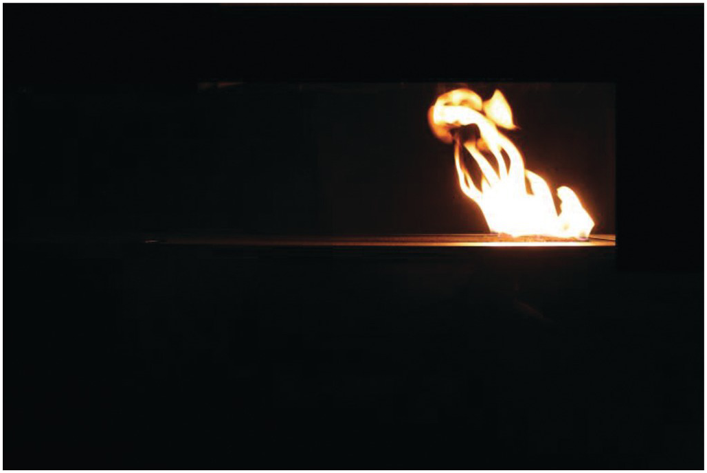
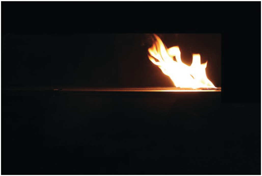
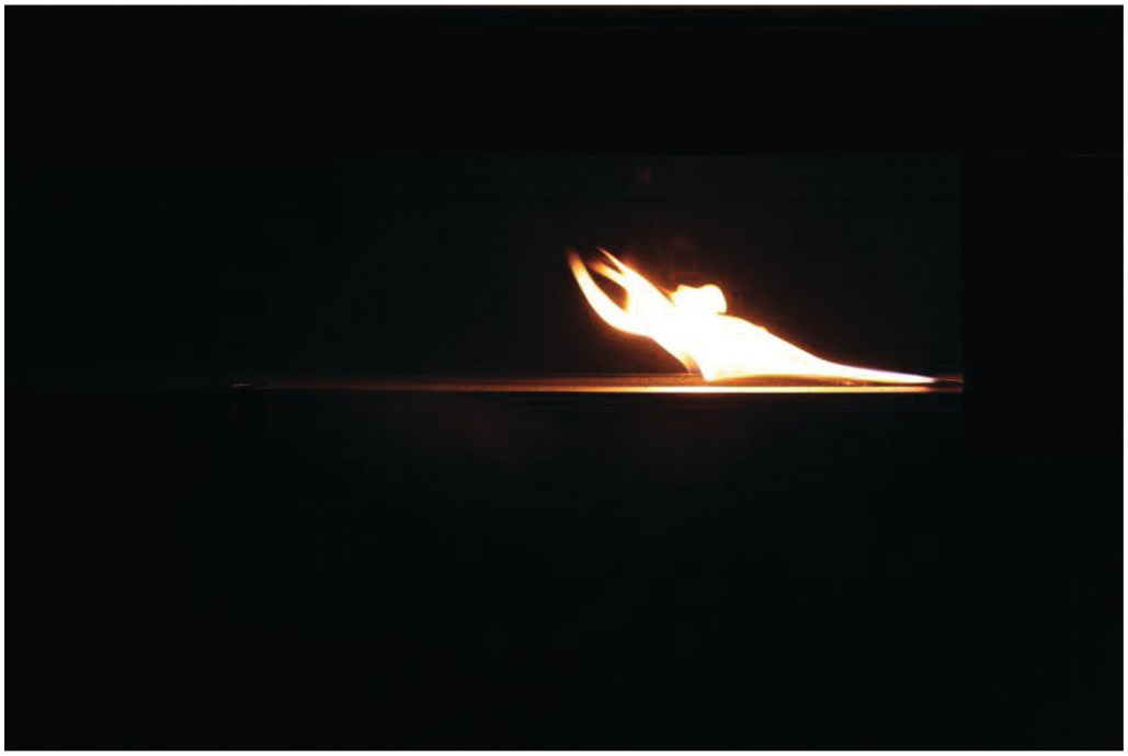
6.3.2 Oxidizer Dilution Quenching of a Turbulent, Methane Line Flame
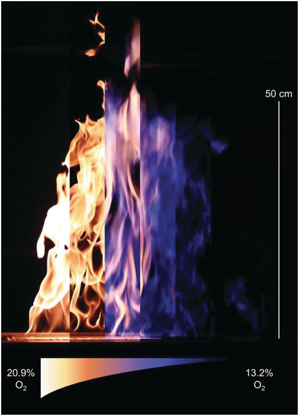
Nitrogen gas (99.99% pure) is added to a co-flowing oxidizer stream of ambient air at atmospheric temperature and pressure to accomplish variations in the oxidizer oxygen concentration. The co-flowing oxidizer surrounds a 50 cm-wide by 50 cm-long stainless-steel slot burner flowing methane gas (99.5% pure) at 1.0 g/s to yield a nominal 50 kW turbulent diffusion flame with a mean visible flame height of roughly 50 cm. Image slices from left to right depict flame response to decreasing oxidizer oxygen concentration. From left to right, image slices correspond to oxidizer oxygen concentrations of 20.9 vol% O2, 17.5 vol% O2, 15.6 vol% O2, 14.8 vol% O2, 13.8 vol% O2, and 13.2 vol% O2.
With reducing oxidizer oxygen concentration, soot production is inhibited and flame temperature is reduced, leading to a transition in flame color from bright yellow to pale blue. Here, yellow flame regions are made visible by the incandescence of soot particles, and blue flame regions are made visible by the relatively dim luminescence of CH radicals. The dim blue regions are visible only in the absence of the comparably bright soot incandescence.
Acknowledgements
Support for this work has been provided by the U.S. National Science Foundation (NSF-GOALI Award #1236788). Additional support provided by FM Global and United Technologies Research Center is gratefully acknowledged.
Source References
Other References
6.3.3 Indirect Extinguishment of a Diffusion Flame with Water Vapor
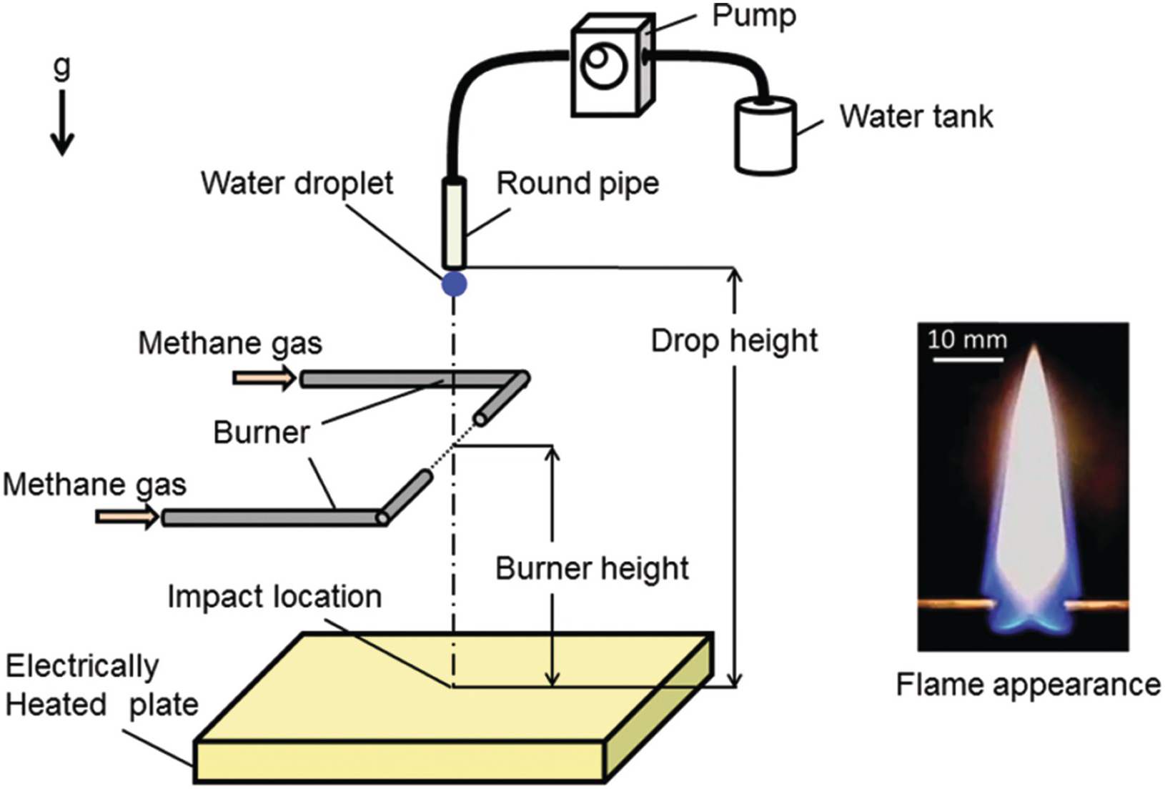
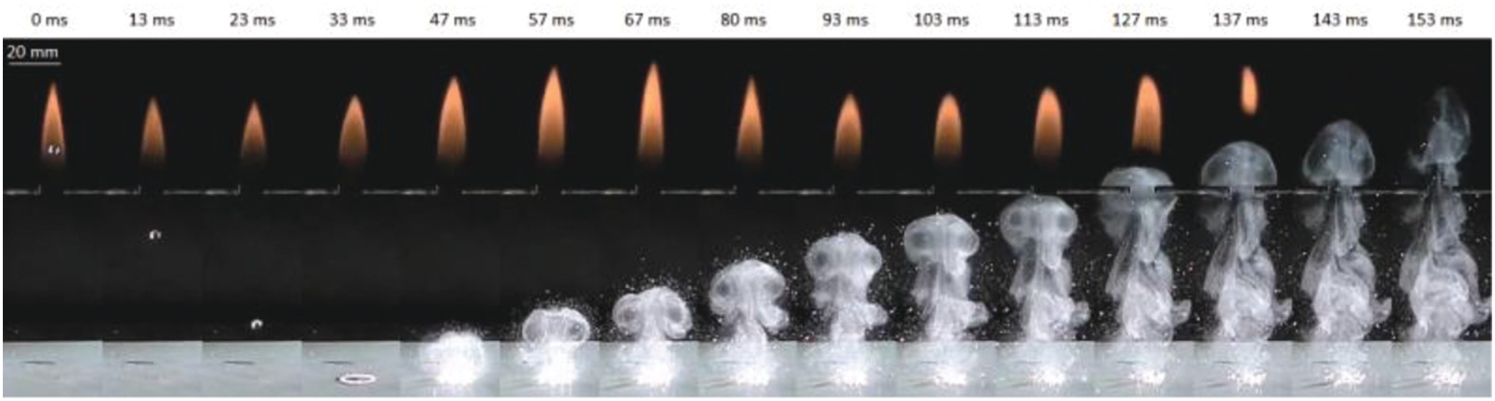
Figure 6.39 shows the experimental apparatus to extinguish a methane–air diffusion flame with water vapor produced by impacting a single water droplet onto an electric heated plate. The plate surface temperature was varied from 100°C to 430°C. The water droplet whose diameter was about 3.2 mm was dropped from a height of 400 mm. The diffusion flame was formed with a horizontally-opposed tube burner, whose outer and inner diameters were 3 mm and 2.6 mm, respectively. The distance between the burner exits was 10 mm. The volumetric flow rate of methane gas was set at 0.23 l/min. The flame appearance is shown in Figure 6.39, and the flame height was about 40 mm. The distance from the burner to the heated plate surface (burner height) was varied from 32 to 102 mm. Figure 6.40 shows a sequential images of the impacting and boiling behaviors of the water droplet on the plate heated at 250°C, which were recorded by using a high-speed camera (exposure time: 1/10,000 s; frame rate: 10,000 fps) and a metal halide lamp. At 4.0 ms after the droplet impact, the shape of the water droplet deforms into the axisymmetric circular thin liquid film. At 5 ms, nucleate boiling begins in the thicker liquid layer at the outer edge of the circular water film. Then, at between 5.5 ms and 7.5 ms, the ring shape of the nuclear boiling region spreads inwardly to the center point of the liquid film. At 8 ms, spreading of the boiling region reaches the center of the liquid film. After that, the liquid film breaks up into droplet particles with various diameters. Figure 6.41 shows the extinguishing process of the flame at the plate temperature of 250°C and the burner height of 72 mm. The water vapor is basically invisible, but the water fog formed by condensation of the water vapor due to cooling is visible. Therefore, the motion of the visible water fog is considered to be almost the same as the water vapor behavior. The images were recorded with a digital camera (exposure time: 1/2,000 sec; frame rate: 300 fps). It is found that at 57 ms in Figure 6.41, the water vapor vortex ring is formed from the impacted water droplet. Then the vortex ring travels upward to the flame. At 113 ms, the vortex ring reaches the flame base, and the local extinction at the flame base region occurs at 127 ms. After that, the luminous flame area is blown downstream and finally the extinguishment is achieved. Thus, the produced water vapor is enough to extinguish the flame and to be transported effectively to the combustion zone by the vortex ring.


In the confined fire space, there are high-temperature solid surfaces such as wall, ceiling, and floor heated by flames and fire plumes and pyrolysis region of the flammable materials. When the large water droplet is impinged onto the high-temperature solid surface in the burning area, it can be expected that the water droplet absorbs heat from the solid surface and turns rapidly into water vapor, and by producing a large amount of water vapor, fire extinguishment may be achieved. Based on the above considerations, we have investigated an extinguishing method with water vapor caused by impacting large water droplets onto the headed solid surface, which is called an indirect fire attack method.
Source Reference
Other Reference
6.4 Fire Whirls
6.4.1 Fire Whirl

Fire whirls are one of the most destructive yet fascinating fire phenomena. They are often observed in large-scale urban and wildland fires and have caused incredible destruction due to their intensification of combustion and ability to spread fires during large conflagrations. This figure shows the full structure of a 30 cm-diameter heptane pool fire whirl created in the laboratory at the University of Maryland. The fire whirl is generated by adding swirl through four tangential slits around the edge of the walled test region.
Reference
6.4.2 Fire Whirls from Multiple Sources

Fire whirls often occur in large-scale urban and wildland fires. They are disastrous and capable of destroying everything in their paths. This picture shows laboratory-scale 30 cm-tall fire whirls generated by three identical pool fires placed at three different heights. These pool fires are placed inside a rectangular glass enclosure (35 × 35 × 60 cm) with an open top and 5 cm gaps placed at each of the four corners. Each pool first produces an individual long but unstable rotating fire. After a transition of about 30 s, the three pool fires start braiding into a single strong fire whirl as shown in the image, and consume the liquid fuel 10 times faster than the original individual pool fires.
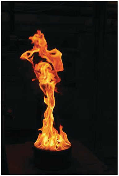
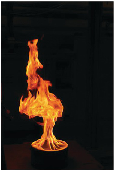
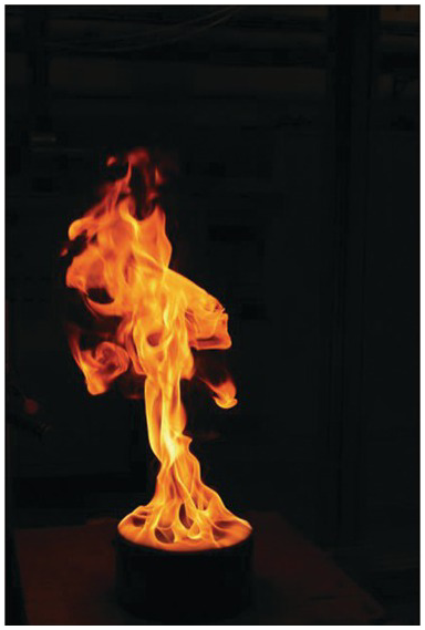
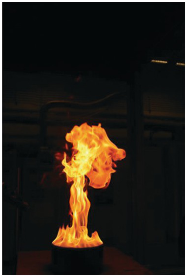
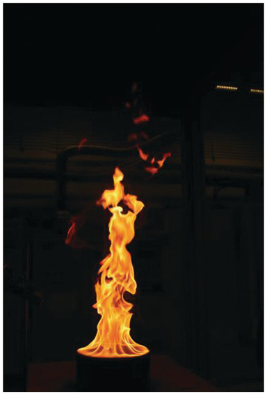
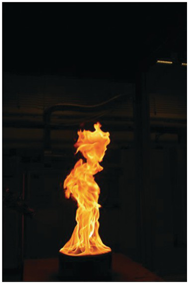
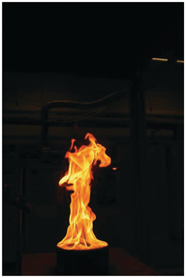
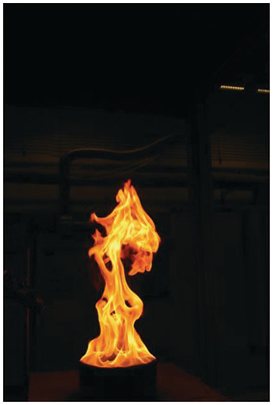
6.4.3 Formation of a Fire Whirl
Fire whirls require specific conditions and wind and fire to form. These conditions are often met in the laboratory via sidewalls with specifically placed slits, but in nature, topographical barriers, wind, and even the fire itself can generate the required circulation to form a central vortex core that results in this fascinating intensification of combustion. During the formation process, a traditional pool fire transitions once acted upon by external circulation, resulting in tilting and stretching, as shown below, until a stable vortex core is formed.
Reference
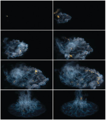
6.4.4 The Blue Whirl
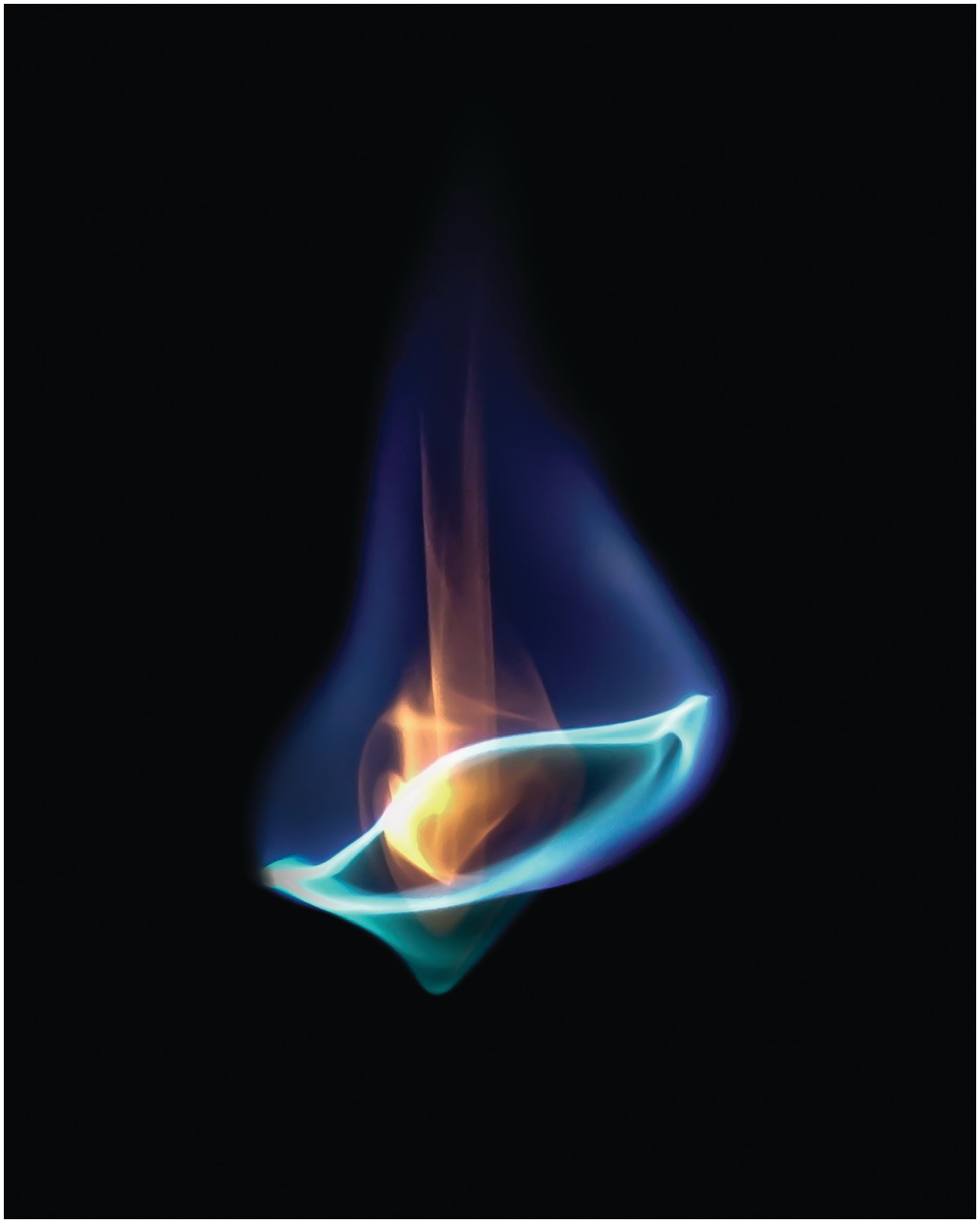

The blue whirl is a regime of the fire whirl that produces no soot, even while burning liquid hydrocarbons directly. In this experiment, a fixed-frame self-entraining fire whirl setup over a water surface was used to create a traditional yellow fire whirl using heptane. The fire whirl (~70 cm in height) was then observed to develop into a small blue whirl ~5 cm in height.
In this image, the recirculation within the blue cone region can be visualized using the soot particles, some of which are seen leaving the whirl through the top.
The recirculating regions are typical of the bubble mode of vortex breakdown, although a complete understanding of the flame regime does not exist yet.
This image was captured using a digital camera at f/2.8, 1/25 s, ISO-800.
Acknowledgements
This research was supported by NSF CBET-1507623, CBET-1554026, Minta Martin Endowment Funds in the Department of Aerospace Engineering, and Glenn L. Martin Institute Chaired Professorship at the A. James Clark School of Engineering.
6.4.5 Inside the Whirl
Fire whirls involve complex flame structures that have not yet been fully understood. These images were taken at the US Forest Service, Missoula Fire Sciences Laboratory where fire whirls are studied as they relate to hazards in large wildland fires. A close shot of the many flame structures in a vortex core are visible on the left, while a shot from above the fire whirl looking down the “donut hole” created by the whirl reveals the swirling motion in the center of the vortex core.
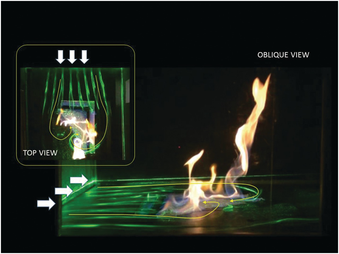
6.4.6 Twin Fire Whirls over a Methanol Liquid Pool in a Small Wind Tunnel

This image shows twin fire whirls formed over a liquid methanol pool mounted in a small wind tunnel (both top and oblique views). An L-shaped tray 20 mm wide filled with ethanol was embedded in the floor of the wind tunnel, and a triangle shape of cotton sheet soaked in ethanol was placed inside the L-shape. A specially designed wind tunnel was used, which has been developed for a scale model experiment of the fire and installed at Toyohashi U Tech. The fuel tray was water-cooled, and its fuel level could be maintained during the test event. A uniform flow of 0.4 m/s was applied to the fire field, and soon twin fire whirls appeared as shown. The main fire whirl that appeared at the edge of the fuel tray showed the clockwise spin, while the small fire whirl that appeared on the inside of the L-shape showed the counterclockwise spin. Twin vortexed flames can be nicely arranged to show counter-vortex formation in the fire field.
This experiment aimed to examine the location in which fire whirls may appear under various environmental conditions (e.g., flow velocity, tray size). This test facility provided steady conditions so that the location of twin fire whirls under the prescribed condition could be well explored. Scale model test results were compared to a 5 m scaled fire whirl test performed at Building Research Institute (BRI), Japan, and it was found that the potential location of the fire whirl could be predicted well by our scale model experiment.
Acknowledgements
This research was partially funded by Takahashi Industrial and Economic Research Foundation (FY2013), JKA (FY2014-2015), The Hibi Foundation (FY2015), and Grant-in-Aid for Challenging Exploratory Research (#15K12472) (FY2015-2016). Authors appreciate fruitful discussions with Mr. Sekimoto from Sekimoto PE., Japan, and Prof. Kazu Kuwana from Yamagata University, Japan.
References
6.5 Wildland Fires
6.5.1 Wildfires
Wildfires burn somewhere around the globe every day, destroying vegetation and property and producing significant emissions into the atmosphere. While they can be incredibly destructive, fires are also an essential process for many ecological systems, occurring for millennia. Here, the most intense type of wildland fire, a crown fire, is shown as part of the crown fire experiments performed in the Northwest Territories, Alberta, Canada. This prescribed fire experiment included several experimental fire shelters used to protect firefighters from burnover. Prescribed fires are often used to reduce dangerous fuel levels and restore ecosystems; however, they can also be used for research and firefighter safety studies.
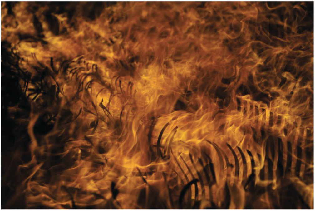
6.5.2 Wildland Fire Spread
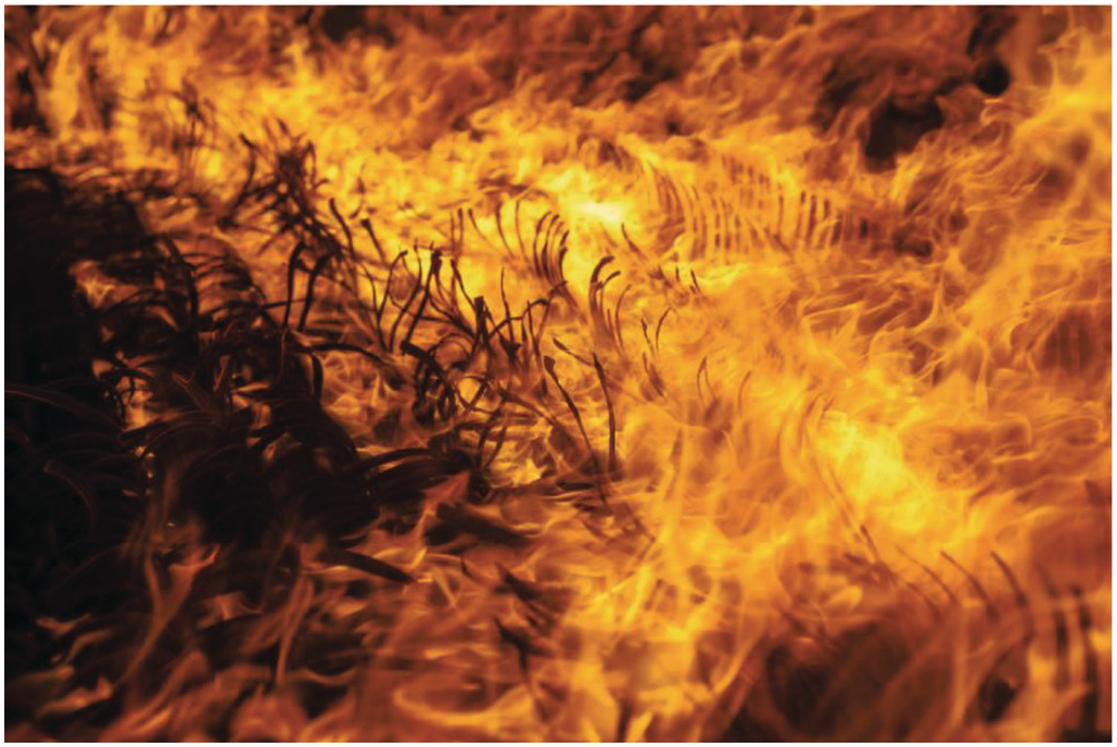
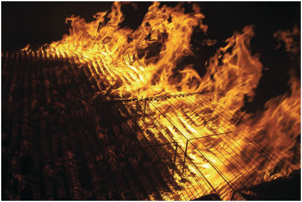

One of the greatest challenges in wildland fire is accurately predicting its spread. Experiments conducted at the US Forestry Service, Missoula Fire Sciences Laboratory, used huge arrays of small cardboard “tines” to reproduce wildland fire spread in a 3 m × 3 m diameter fire wind tunnel with a homogenous fuel source. The experiments showed that the flame structure is quite complex, with “peaks and troughs” formed in the flame front that allowed “bursts” of flame to push hot gases forward and preheat or ignite fine fuels far ahead of the mean flame front. An array of fine thermocouples, shown in one pane, was used to track the flame and these forward bursts. This knowledge has been used to understand the flame spread process and inform model development.
Reference
6.5.3 Firebrands

Firebrands, the small burning embers that break off structures or vegetation during wildland fires, present an enormous hazard to life and property. They can create a “shower” that ignites structures and wildlands far from the original fire front. In this photo a firefighter is seen walking through flying embers as flames from the Sayre Fire burns in the Granada Hills section of Los Angeles. The fire originated in Sylmar and jumped two freeways as it burned west into Granada Hills.
6.5.4 Firebrand Generation

Firebrands, small burning embers that are responsible for ignition of many homes during wildland fires, are produced from a 5.2 m Douglas-Fir tree under no applied wind field.
Reference
6.5.5 NIST Dragon

A unique experimental apparatus, the NIST Dragon, has been developed to reproduce a “shower” of firebrands that a structure may experience during a large wildland fire. The firebrands shown here produced smoldering ignition in the shredded hardwood mulch bed (foreground). This transitioned to flaming ignition in the mulch bed, and the cedar fencing has just ignited in this image. Shredded hardwood mulch was intended to represent various fine fuels that are often found adjacent to fencing in the Wildland–Urban Interface (WUI). The dangers of wind-driven firebrand showers are apparent.
Reference
6.6 Smoldering Combustion
6.6.1 The Great Fire of London

The picture was taken in 2016 during the celebration of the anniversary of the Great Fire of London of 1666. The remains of the buildings can be clearly seen in the flames, adding a sense of scale. There is a large vortex clearly visible in the flames. It is a good impression of how the Great Fire of London might have looked like to observers back in the day.
6.6.2 Smoldering Combustion

Smoldering is a lower-temperature, flameless form of combustion that evolves heat due to oxidation directly on the surface of the fuel. This picture shows the smoldering of softwood biochar pellets (10 mm × 2 mm × 2 mm), which were produced from biomass. The glowing parts are smoldering components of the biochar, with combustion and intense heat being emitted. The darker parts are char, where combustion has not yet taken place. Biomass is becoming widely used for energy production, so laboratory-scale studies like these are being conducted to understand their behavior in larger scales and prevent accidental fires from developing in biomass transport and storage.
6.6.3 Firing Black to White

When a solid fuel is burned, it chars, with combustion reactions progressively turning it into ash. For complete combustion, all the original fuel turns into ash. With incomplete combustion, different amounts of char and ash ratios are produced. The picture shows the transition of charcoal fuel (black) to ash (white), with the sample containing only char on the left, followed by each sample containing an ever-increasing amount of ash until the right-most sample contains pure ash from complete combustion.
6.6.4 From Biomass to Ash

Biomass is an important fuel for power generation, and its use is increasing. However, it is associated with many fire safety issues. As a porous reactive media, it is prone to self-heating, caused by oxidation reactions at low temperatures. Surrogate biomass (rice husks) reheated in an oven at temperatures above 150°C produces torrefied biomass. Initially the rice husk is torrefied, with increasing oven temperatures causing charring leading the biomass to ignition above 190°C, leaving only ash (top).
6.6.5 Thermal Decomposition and Intumescent Behavior of Rigid Poly(vinyl chloride)


The images show gasification of rigid poly(vinyl chloride) (PVC) exposed to a radiant heat flux of nominally 30.9 kW/m2 in a nitrogen atmosphere. Isolated from gas-phase combustion and solid surface oxidation, the PVC demonstrates highly charring and intumescent behavior during pyrolysis. These experiments, performed in a well-controlled gaseous environment, provide repeatable mass loss rate, spatially resolved temperature, and quantitative sample shape data, which is required to construct a comprehensive pyrolysis model. This series of images represents various stages of the PVC thermal decomposition and intumescent process at 50, 150, 300, 400, 600, and 700 s.
Acknowledgements
This work was made possible by funding from the National Science Foundation